

QSz
663
To be handed to the workshop!
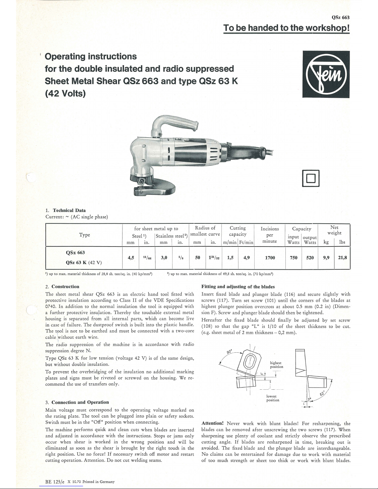
Operating instructions
for the
double insulated and radio suppressed
Sheet Metal Shear QSz
663
and type QSz
63
K
(42
Volts)
1. Technical
Data
Current: ~ (AC
single phase)
for sheet
metal
up
to
Radius of
Cutting
Incisions
Capacit
y
Net
Type
Steel
1
)
Stainless steel
2
)
smallest
curve
capacity
per
input I output
weight
mm
I
m.
mm
I
m.
mm
m.
m/
min
I Ft!min
minute
Watts Watts
kg
I
lbs
QS:z:
663
4,5
11
/64
3,0
1
/s
50
13
1
/a2
1,5 4,9
1700 750 520 9,9
21,8
QSz 63 K (42 V)
1
)
up
to
max. material thickness
of
28,4 sh.
ton
/sq. in. (40
kp/mm
2
)
2
)
up
to
max. material thickness of 49,8 sh. ton/sq. in. (70 kp/
mm'
)
2. Construction
The
sheet
metal
shear
QSz
663 is
an
electric
hand
tool fitted
with
protective insul
ation
according
to Cla
ss
II
of
the
VDE
Specifications
0740.
In addition
to
the
norm
al i
nsulation the tool is equipped
with
a
further
protective
insu,lation.
Thereby
the
touchable
external
metal
housing is
separated
from
all
internal
parts,
which
can
become live
in
case
of
failure.
The
dustproof
switch
is
built
into
the
plastic handle.
The
tool
is
not
to
be
earthed
and
must be connected
with a two
-core
cable
:
without
earth
wire.
The
r~dio
suppression
of
the
machine
is
in accordance with radio
suppression degree
N.
Type
QSz
63 K
for
low
tension
(voltage
42 V) is
of
the same design,
but
without
double insulation.
To
prevent
the
overbridging
of
the ins
ulation
no
additional
marking
plates
and
signs must be
riveted
or
screwed
on
the
housing. We re-
commend
the
use
of
transfers
only.
3. Connection and Operation
Main
voltage must correspond
to
the
operating
voltage
marked
on
the
rating
plate.
The
tool
can
be
plugged
into
plain
or
safety
sockets.
Switch must be in
the
"Off"
position
when
connecting.
The
machine
performs
quick
and
clean cuts
when
blades are inserted
and
adjusted in accordance
with the instructions . Stops
or jams
only
occur w
hen shear
is
worked
in
the wrong position a
nd
will be
eliminated as soon as
the
shear is
brought
by the rig
ht
touch in
the
right
position. Use
no
force!
If
necessary switch off
motor
and
restart
cutting operation.
Attention.
Do
not
cut welding seams.
BE 125/e X 10.70
Printed
in
German
y
Fitting and adjusting
of
the blades
Insert
fixed blade
and
plunger blade (116)
and
secure sli
ghtly
with
screws (117).
Turn
set screw (101)
until
the
corners
of
the
blades
at
highest
plunger
position overcross
at
about
0.5
mm
(0.2 in)
(Dim
en-
sion F). Screw
and
plunger
blade sho
uld
then
be tightened.
Hereafter
the
fixed bl ade should finally be
adjusted
by
set screw
(108) so
that
the
gap
"L"
is
1/10
of
the
sheet thickn
ess
to
be cut.
(e.g. sheet metal
of 2 mm
thickness-
0,2 mm).
highest
position
l
owes
t
p
os
ition
Attention!
Never
work
with
blunt
blades!
For
resharpening, the
blades
ca
n be removed
after
unscrew
ing
the two screws (117). When
sharpening
use
plenty of
coolant a
nd
strictly obse
rve the prescrib ed
cutting
angle.
If
blades are resha
rpened
in
time,
breaking
out
is
avo
ided
. The fixed blade
and
the
plunger
bla
de
are
interchangeable.
No
claims can be
entertained
for
damage
due
to
work with
materia
l
of
too much strength
or
sheet too thick
or
work
with blunt
blades.
81
- -------,_
96
106
105
104
103
102
Q1
~
~
...
I I
'!Al.W~
\
'11:11
Jl
)..
KJO
I
~~ i ~· I ~~ I~~ I ~·
I
97
t:f)
CD
l:C
1:/
""
""
101
108
109
~91,5
QSz 663
3'
35
l l
lllllllllllllilillllllllll
iiiiiiiiiliililiiii
iiillliilil
iiiiiii
l
/N
~I
liif1<'l
~
~~
""t'
I
\
I
( {
·~
1- i
~
·
I
- I .
I
-
-
--
•v
-~
25
26
27
/C
N
/1"1
D
~
35
64
63a
63
32
32b
32c
QSz
63K
"$-
g
......
II
I I
--·
-
--·---
::.
14
62
1C»'
I
28
34
114
115
29
31
I
110 I 111
112 113
I
r
I
+
-·
I
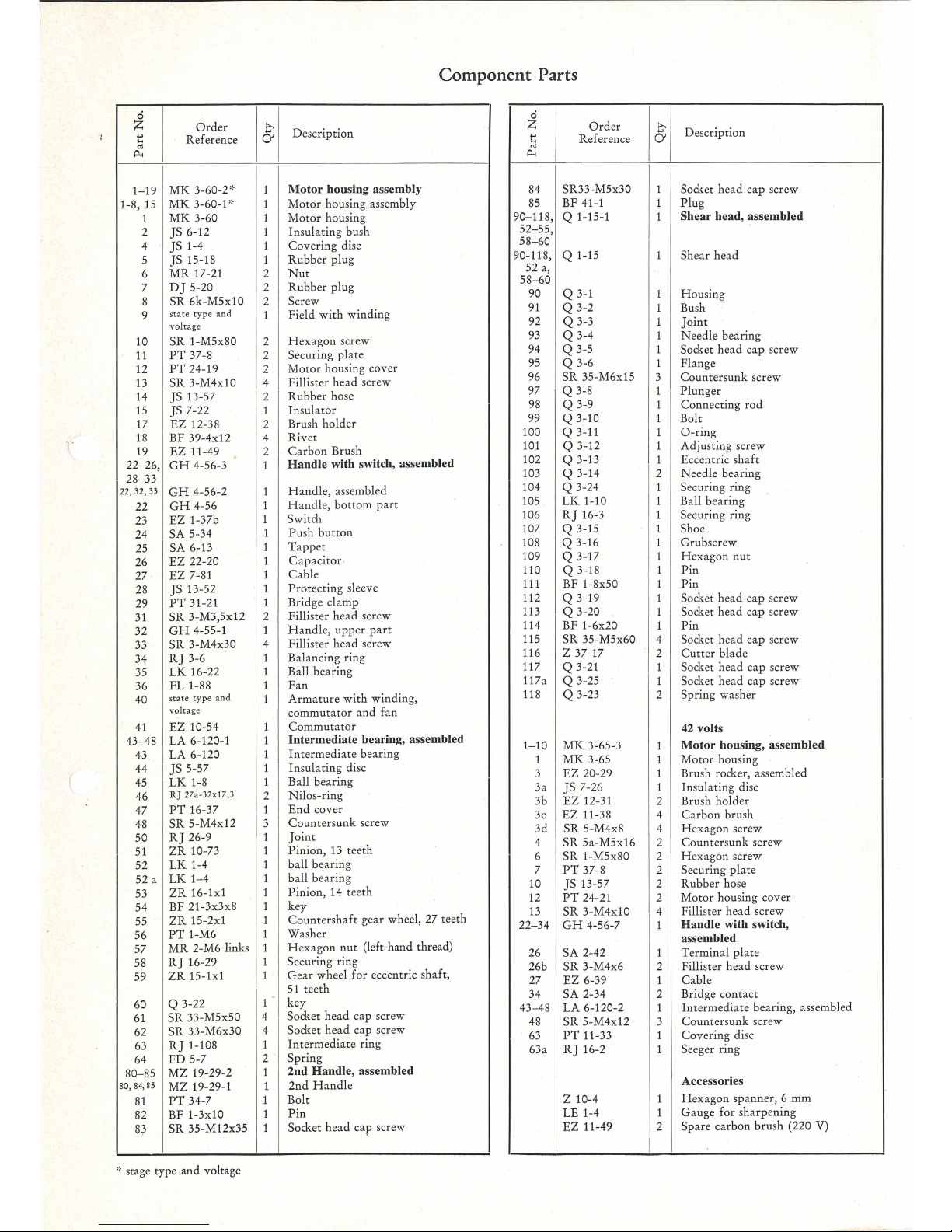
Component Parts
0
z
Order
>.
Description
...,
Reference
6
....
"'
0
z
Order
>.
Description
...,
Reference 6
....
"'
p..
p..
1-19
MK
3-60-2''·
Motor housing assembly
84
SR33-M5x30
1 Socket
head
cap screw
1-8,
15
MK
3-60-P
Motor
housing assembly
85
BF 41-1
1
Plug
1
MK
3-60
Motor
housing
90-118, Q 1-15-1 1
Shear head, assembled
2
JS
6-12
Insulating bush
4
]S 1-4
Covering
disc
5
]S 15-18
Rubber
plug
6
MR
17-21
2
Nut
7
D]
5-20 2
Rubber
plug
8
SR
6k-M5x10 2
Screw
9
state
type
and
1
Field
with
winding
voltage
10
SR
1-M5x80 2
Hexagon
screw
11
PT
37-8 2
Securing
plate
12
PT
24-19 2
Motor
housing cover
13
SR
3-M4x10
4
Fillister
head
screw
14
]S 13-57 2
Rubber
hose
15
JS 7-22
1
Insulator
17
EZ
12-38
2
Brush holder
18
BF 39-4x12 4
Rivet
19
EZ
11-49 2
Carbon
Brush
22- 26,
GH
4-56-3
Handle with switch, assembled
28-33
Handle,
assembled
22, 32,
33
GH
4-56-2
1
22
GH
4-56
1
Handle,
bottom
part
23
EZ
1-37b
1
Switch
24
SA
5-34
1
Push
button
25
SA
6-13
Tappet
26
EZ
22-20
Capacitor
·
27
EZ
7-81
Cable
28
JS 13-52
Protecting
sleeve
29
PT
31-21
1
Bridge clamp
31
SR
3-M3,5x12
2
Fillister
head
screw
32
GH
4-55-1
1
Handle,
upper
part
33
SR 3-M4x30
4
Fillister
head
screw
34
R]
3-6
1
Balancing ring
35
LK
16-22 1
Ball bearing
36
FL
1-88 1
Fan
40
state type and
1
Armature
with
winding,
52-55,
58-60
90-118,
Q 1-15 1 Shear
head
52 a,
58-60
90
Q 3-1 1 Housing
91
Q 3-2 1 Bush
92
Q 3-3 1
Joint
93
Q 3-4 1
Needle
bearing
94
Q 3-5
1
Socket head cap screw
95
Q 3-6 1 Flange
96
SR
35-M6x15
3
Countersunk
screw
97
Q 3-8 1
Plunger
98
Q 3-9 1 Connecting
rod
99
Q 3-10 1 Bolt
100
Q 3-11
1
0-ring
101
Q 3-12
1 Adjusting screw
102
Q 3-13 1
Eccentric
shaft
103
Q 3-14 2
Needle bearing
104
Q 3-24
1 Securing ring
105
LK
1-10 1 Ball bearing
106
RJ
16-3 1
Securing ring
107
Q 3-15
1 Shoe
108
Q 3-16
1 Grubscrew
109
Q 3-17
1
Hexagon
nut
110 Q 3-18 1
Pin
111
BF 1-8x50
1
Pin
112
Q 3-19 1
Socket head cap screw
113
Q 3-20
1
Socket head cap screw
114 BF
1-6x20
1
Pin
115
SR
35-M5x60
4 Socket
head
cap screw
116
z 37-17
2
Cutter
blade
117
Q 3-21 1 Socket head
cap
screw
117a
Q 3-25
1
Socket head
cap
screw
118
Q 3-23 2 Spring washer
voltage
commutator
and
fan
41
EZ
10-54
Commutator
42 volts
43-48
LA
6-120-1
Intermediate bearing, assembled
43
LA 6-120
Intermediate
bearing
44
I JS 5-57
Insulating
disc
45
LK
1-8 1
Ball bearing
46
RJ
27a-32xl7,3
2
Nilos-ring
47
PT
16-37 1
End
cover
48
SR
5-M4x12
I
~
Countersunk
screw
50
R]
26-9
Joint
51
ZR
10-73
Pinion,
13
teeth
52
LK
1-4
ball bearing
52 a
LK
1-4
ball
bearing
53
ZR
16-1x1
Pinion, 14 teeth
54
BF 21-3x3x8
key
55
ZR
15-2x1
Countershaft
gear wheel, 27 teeth
56
PT
1-M6
Washer
57
MR
2-M6 links 1
Hexagon
nut
(left-hand thread)
58
R]
16-29
1
Securing ring
59
ZR
15-1x1
1
Gear
wheel for eccentric shaft,
11 -
51
teeth
60
Q 3-22
key
61
SR 33-M5x50
4
Socket
head
cap screw
62
SR
33-M6x30
4
Socket
head
cap screw
63
R]
1-108
1
Intermediate
ring
64
FD
5-7
2 .
Spring
1-10
MK
3-65-3
1
Motor housing, assembled
1
MK
3-65
1
Motor
housing
3
EZ
20-29 1
Brush rocker, assembled
3a
JS
7-26 1
Insulating disc
3b
EZ
12-31
2 Brush holder
3c
EZ
11-38
4
Carbon
brush
3d
SR
5-M4x8 4
He
xagon screw
4
I
SR
5a-M5x16
2
I
Countersunk
screw
6
SR
1-M5x80
2
Hexagon
screw
7
PT
37-8 2 Securing
plate
10
JS 13-57
2
Rubber
hose
12
PT
24-21
2
Motor
housing cover
13
SR
3-M4x10 4
Fillister
head
screw
22-34
GH
4-56-7 1
Handle with switch,
assembled
26
SA
2-42
1
Terminal
plate
26b
SR
3-M4x6
2
Fillister head screw
27
EZ
6-39 1 Cable
34 SA
2-34
2
Bridge contact
43-48 LA
6-120-2
1
Intermediate
bearing, assembled
48
SR 5-M4x12 3
Countersunk
screw
63
PT
11-33 1
Covering
disc
63a
R]
16-2 1
Seeger ring
80-85
MZ
19-29-2
1
2nd Handle, assembled
80,
84,
85
MZ
19-29-1
1
2nd
Handle
Accessories
81
PT
34-7
1
Bolt
z 10-4
1
Hexagon
spanner, 6
mm
82
BF 1-3x10
1
Pin
LE
1-4 1
Gauge for sharpening
S3
SR 35-M12x35
Socket
head
cap screw
EZ
11-49 2
Spare carbon brush
(220
V)
,,.
stage type and voltage
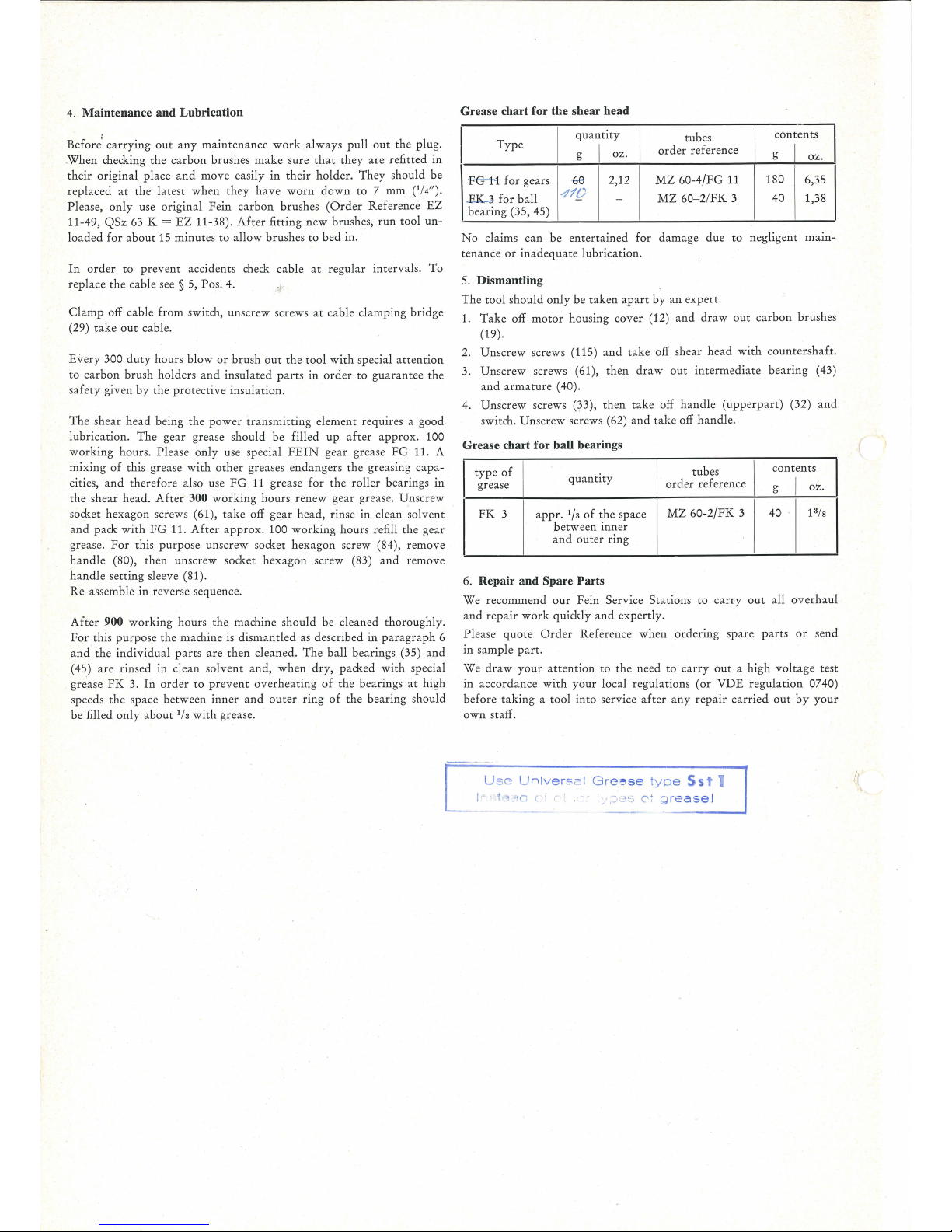
4. Maintenance and Lubrication Grease chart
for
the shear head
Before1 carrying
out
any
maintenance
work
always
pull
out
the
plug.
.
When
checking
the
carbon
brushes
make
sure
that
they
are
refitted
in
their
original
place
and
move
easily
in
their
holder.
They
should
be
replaced
at
the
latest
when
they
have
worn
down
to 7 mm
(1
/4").
Please,
only
use
original
Fein
carbon
brushes
(Order
Reference
EZ
11-49,
QSz
63 K =
EZ
11-38).
After
fitting
new
brushes,
run
tool
un-
I
Type
I
·FG-1- 1
for
gears
.EK..J
for
ball
bearing
(35, 45)
quantity
g
I
oz.
{,6
2,12
-1
1[)
-
I
tubes
contents
ord
er
reference
I
g
oz
.
MZ
60-4/FG
11
180
6,35
MZ
60-2/FK
3
40
1,38
loaded
for
about
15
minutes
to
allow
brushes
to
bed
in.
No
claims
can
be
entertained
for
damage
due
to
negligent
mam-
tenance
or
inadequate
lubrication.
In
order
to
prevent
accidents check cable
at
regular
intervals.
To
replace
the
cable see § 5, Pos. 4.
.,
5. Dismantling
Clamp
off cable
from
switch, unscrew screws
at
cable
clamping
bridge
(29)
take
out
cable.
Every
300
duty
hours
blow
or
brush
out
the
tool
with
special
attention
to
carbon
brush
holders
and
insulated
parts
in
order
to
guarantee
the
safety
given
by
the
protective
insulation.
The
shear
head
being
the
power
transmitting
element requires a
good
lubrication.
The
gear
grease should
be
filled
up
after
approx.
100
working
hours. Please
only
use special
FEIN
gear
grease
FG
11. A
mixing
of
this grease
with
other
greases
endangers
the
greasing
capa-
cities,
and
therefore
also use
FG
11
grease
for
the
roller
bearings
in
the
shear
head.
After
300
working
hours
renew
gear
grease,
Unscrew
socket
hexagon
screws (61),
take
off gea r
head,
rinse
in
clean solvent
and
pack
with
FG
11.
After
appro
x. 100
working
hours
refill
the
gear
grease.
For
this
purpose
unscrew
socket
hexagon
screw (84),
remove
handle
(80),
then
unscrew
socket
hexagon
screw
(83)
and
remove
handle
setting
sleeve (81).
Re-assemble in reverse sequence.
After
900 w
orking
hours
the
machine
should
be
cleaned
thoroughl
y.
For
this
purpo
se
the
machine is
dismantled
as described
in
paragraph
6
and
the
individu
al
parts
are
then
cleaned.
The
ball
bearin
gs (35)
and
(45)
are
rinsed
in
clean
solvent
and,
when
dry,
packed
with
special
grease
FK
3.
In
order
to
prevent
overheating
of
the
bearings
at
high
speeds
the
space
between
inner
and
outer
ring
of
the
bearing
should
be
filled
only
about 1/s
with
grease.
The
tool
should
only be
taken
apart
by
an
expert.
1.
Take
off
motor
housing
cover
(12)
and
draw
out
carbon
brushes
(19).
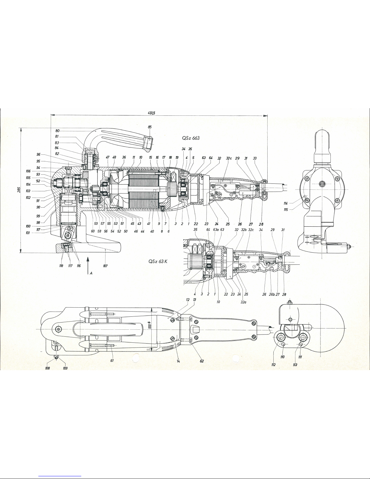
2.
Unscrew
screws (115)
and
take
off shear
head
with
countershaft.
3.
Unscrew
screws (61),
then
draw out
intermediate
bearing
(43)
and
armature
( 40 ).
4.
Unscre
w screws (33),
then
take
off
handle
(upperpart)
(32) a
nd
switch.
Unscrew
screws (62)
and
take
off
handle.
Grease chart for ball bearings
I
type
of
I
I
tubes
I
contents
quantity
order reference
I
grease
g
oz.
FK
3
appr
. 1/a
of
the
space
bet
ween
inner
MZ
60-2/FK
3
40 !3/s
and
outer
ring
6. Repair and Spare Parts
We
recommend
our
Fein
Service
Statio
ns
to
carry
out
all over
haul
and
repair
work quickly
and
expertl
y.
Please
quote Order
Reference when
ordering
spare
parts
or
send
in
sample part.
We
draw
your
attention
to
the
need
to
carry
out a high
voltage
test
in
accordance
with your
local
regulat
ions (
or
VDE
regulation
0740)
before
taking
a tool
into
service
after any
repair
carried
out
by
your
own
staff.
U
sc Univer
sa l
G
re::~se
typ
e
Ss
t 1
1·
h:1a
c ·
:_,
)-5S
o: g
rease
I
 Loading...