

(
QSz
649
~
be handed to the workshop
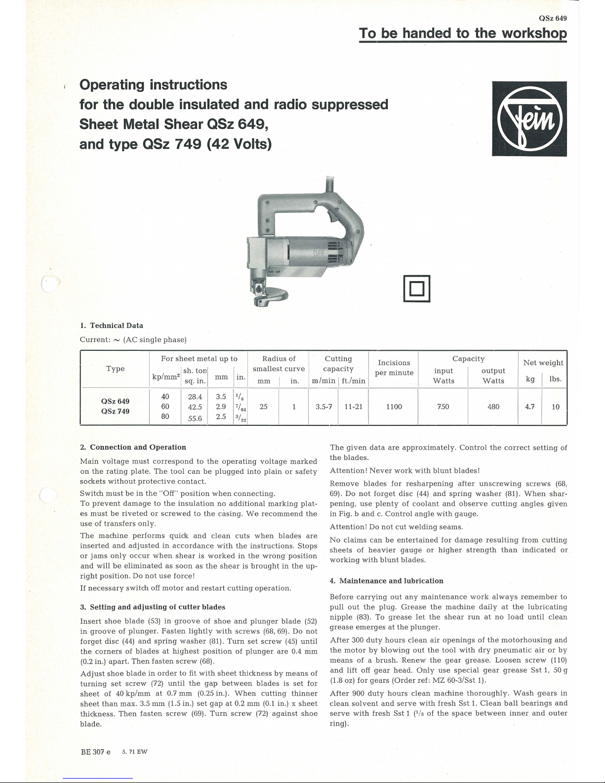
Operating instructions
for the
double insulated and radio suppressed
Sheet
Metal Shear QSz
649,
and type QSz 7
49
(42
Volts)
1. Technical
Data
Current: ~ (AC
single
phase)
I
For
sheet
metal
up
to
Radius
of 1·
Cutting
Incisions
Capacity
Net
weight
Type
I j
sh.
ton
i
I
in.
smallest
curve
capacity
per
minute
input
I
output
kp
mm
2
.
mm
mm I in
. 1
m/min I ft./min
Wa
tts
Watts
kg I lbs
.
1
sq.
m.
40
28.4
3.5
lfs
I
QSz
649
QSz
749
60
42.5
2.9
7
/64
1
25
1
3.5-7
11-21
1100 750 480 4.7
10
80
55.6
2.5
3
/32
2.
Connection
and
Operation
Main
voltage
must
correspond
to
the
operating
voltage
marked
on
the
rating
plate.
The
tool
can
be
plugged
into
plain
or
safety
sockets
without
protective
contact.
Switch
must
be
in
the
"Off" position when
connecting
.
To
prevent
damage
to
the
insulation
no
additional
mar
king plat-
es
must
be
riveted
or
screwed
to
the
casing.
We
recommend
the
use
of
transfers
only.
The
machine
performs
quick
and
clean
cuts
when
bla
des
are
inserted
and
adjusted
in
accordance
with
the
instru
ctions. Stops
or
jams
only
occur
when
shear
is worked
in
the
wrong
pos
ition
and
will
be eliminated
as
soon
as the
shear
is
brought
in the
up-
right
position.
Do
not
use
force!
If
necessary
switch
off
motor
and
restart
cutting
operation.
3.
Setting
and
adjusting
of
cutter
blades
Insert
shoe
blade
(53)
in
groove
of
shoe
and
plunger blad
e (52)
in
groove of
plunger.
Fasten lig
htly with
screws
(68, 69).
Do
not
forget
disc
(44)
and
spring
washer
(81).
Turn
set
screw
(45) until
the
corners
of
blades
at
highest
position
of
plunger
are
0.4
mm
(0.2 in.)
apart.
Then
fasten
screw
(68).
Adjust
shoe
blade
in
order
to
fit
with
sheet
thickness
by
mea
ns
of
turning
set
screw
(72)
until
the
gap
between
blades
is
set
for
sheet
of
40
kp/mm
at
0.7
mm
(0.25 in.).
When
cutting
thinner
sh
eet
than
max.
3.5
mm
(1.
5 in.)
set
gap
at
0.2 mm
(0.1
in.) x
sheet
thickness.
Then
fasten
screw
(69).
Turn
scr
ew
(72)
against
shoe
blade.
BE 307 e 5. 71
EW
I
The
given data
are
approximately.
Control
the
correct
setting
of
the
blades.
Attention! Never
work with
blunt
blades!
Remove
blades
for
resharpening
after
unscrewing
screws
(68
,
69).
Do
not
forget
disc
(44)
and
spring
washer (81
).
When
shar-
pening, use
plenty
of
coolant
and
observe
cutting
angles given
in
Fig. b
and
c.
Control
angle
with gauge.
Attention!
Do
not
cut wel
ding
sea
ms.
No
claims
can
be
entertained
for
damage
resulting
from cutt
ing
sheets
of
heavier
gauge
or
high
er
strength
than
indicated
or
working
with blunt
blad
es.
4.
Maintenance
and
lubrication
Before
carrying
out any
mainte
nance
work alw
ays
remember
to
pull
out
the
plug.
Grease
the
machine
daily
at
the
lubricat
ing
n
ipp
le (83).
To greas
e l
et the
shear
run
at
no
load until
clean
grease
eme
rges
at
the
plunger.
After
300
duty
hours
clean air
openings
of
th e mot
orhousi
ng
and
the
motor
by
blowing
out the
tool
with
dry
pneumatic
air
or
by
means
of a brush.
Rene
w t
he
gear
grease.
Loosen
screw
(110)
and lift
off
gear
head. On
ly
use
special
gear
grease
Sst
1, 50 g
(1.8 oz) f
or
gears
(Ord
er
ref:
MZ
60-3/Sst
1).
After
900
duty
hours
clean
mac
hine thorough
ly.
Wash
gears
in
clean
solvent
and
serve
with fres
h S
st
1. Clean
ball
bearings and
ser
ve
with fresh
Sst
1 (lh of t
he
space
bet
ween
inn
er
and outer
ring).

69
41
~3
57
33
~
11
12
106
-----
103
10~
107
118
~
plunger
blade
~00
""'"
Fig. a
'/,"~
~--,
r--:::J
' I !
'\
I i I \
I j .
~
~
!
J I
I - i
i !
;,
12' L---, :, .
,.
b---l
. j I
-$-
.
L __
_j}__
L
_______
...J
Fig. b
117
111
111
110
~~~~~
~-----
88
?\ir-------
89
70 76
68
~~
81
72
...-·'\
Fig. c \ \
/
""''-
......
"""'\
/ \
/_../
---~
....
\_)
b~~
~
..
~

Component Parts
ci
ci
z
Order
l><
.....
Reference
a
Description
....
<0
z
Order
l><
.....
Reference
a
Description
....
<0
0..
0..
1-12
MK
3-99-8 1
motor
housing,
assembled
72
Q 5-72
1
threaded
pin
1
MK3-99
1
motor
housing
76
Q5-76
2
cylindrical
pin
2, 3 EZ 12-52-1
2
carbon
holder,
assembled
79
BF
21-4x4x10
1
key
2 EZ 12-52
2 c
arbon
holder
81
Q 5-81
1
spring
ring
3
FD 7-32
2
spring
83
MZ
31-1
1
lubricating
nipple
4
SR 41-M3.5x10
4
fillister
screw
87
Q 5-87
1
square
ring
5 EZ
-11-67
2
carbon
brush
88
BF
29-130
1
deflector
6
SR3-M4x6
2
cy
lindrical
screw
89
SR5-M6x15
2
countersunk
screw
7
state
ty pe
I
1
pole
housing,
assembled
a
nd voltage
with
winding
8
I
PT
37-13
2
spring
washer
95-109
GH
4 83-3
1
bow
handle,
assembled
100109
GH
4-83-2
1
bow
handle,
assembled
9
SR 1-M4x60
2
hexagon
screw
95
JS
13-90
1
cable
protecting
sleeve
10
JS28-10
1
air
guiding
ring
96
EZ 7-143
1
cable
(
11
PT
27-40
2
cover
12
SR 38-4,2x
13
4
screw
100
EZ 1-79
1
switch
101
PT
31-21
1
clamping
bridge
25-29
sta
te ty pe
1
armature
102
SR
38-3.5x16
2
screw
and
volt
age
29
FL
4-10
1
fan
32-89
GH
9-7-3
1
shear
lead,
assembled
32
LA 6-178
1
intermediate
bearing
33-89
GH
9-7-2
1
outer
bearing,
assembled
103
EZ 22-57
1
capacitor
104
JS
16-41
1
plug
105
JS
16-42
1
plug
106-
bow
handle,
assembled
109
GH
4-83-1
1
33
LK 1-2
1
groove
ball
bearing
109
SR
38-4.2x25
4
screw
34
ZR 16-11-1
1
pinion
110
SR33-M5x65
4
hexagon
socket
screw
35 ZR !5-33 x
0.
75
1
gear
wheel
111
PT
5d-M5
10
securing
plate
36
PT
8-186
1
·
disc
112
RJ
12-65
1
sealing
ring
37
ZR15-39x 1
1
gear whe
el
113
LK 16-46
1
groove
ball
bearing
39-89
GH
9-7-1
1
outer
bearing,
assembled
114
LK
16-10
1
groove
ball
bearing
39
Q 5-39
1
plunger
115
SR 33-M5x
18
4
hexagon
socket
screw
40
Q 5-40
1
bolt
116
SR3-M4x6
1
screw
41
Q 5-41
1
bush
117
SR33-M5x35
2
hexagon
socket
screw
42
GH9-7
1
outer
bearing
118
MR
1-M5
2
screw
43
Q 5-43
1
shoe
44
Q 5-44
1
disc
42
Volts
45
Q 5-45
1
adjusting
screw
46
Q 5-46
1
connecting
rod
1-12
MK
3-99-11
1
motor
housing,
assembled
47
RJ
16-37
2
securing
ring
2,
3
EZ 12-53-1
2
carbon
holder,
assembled
48
Q 5-48
1
eccentric axle
2
EZ 12-53
2
carbon
holder
49
Q5-49
1
clamping
ring
5
EZ 11-52
2
carbon
brush
52 z 37-31
1
plunger
blade
95
JS
13-52
1
cable
protecting
sleeve
53
z 37-32
1
shoe
blade
96
EZ 6-162
1
cable
57
LK 1-2
1
groove
ball
bearing
58
LK 16-1
1
groo
ve
ball
bearing
Acessories
59
LK 16-2
1
groove
ball
bearing
60
Q5-60
1
needle
cage
MZ
18-14
1
holding
pin
64
RJ
16-6
1
securing
ring
LE
1-2
1
gauge
66
RJ
16-12
1
securing
ring
z 10-10
1
hexagon
socket
wrench
68
SR
35-M6x18
1
hexagon
socket
screw
z 10-11
1
hexagon
socket
wrench
69
SR
35-M6x15
1
hexagon
socket
screw
EZ 11-52
2
spare
carbon
brush
(42 V)
70
Q 5-70
1
hexagon
socket
screw
EZ 11-67 2
spare
carbon
brush

To
dismantle
tool
see
paragraph
5.
Clean
electric
parts
only
dry.
The
carbon
brushes
should
be
replaced
at
the
latest
when
they
have
worn
down
to 7 mm
(
1
/•"
).
For
replacing
see
paragraph
5,
pos.
2.
Please,
only
use
original
FEIN
carbon
brush
es
(Order
Re-
ference
EZ 11-67).
After
replacing
carbon
brushes
make
sure
that
they
are
refitted
in
their
original
place
and
that
they
move
easily
in
their
holder.
After
fitting
new
brushes,
run
tool
unloaded
for
about
15
minutes
to
allow brushes
to
bed
in.
In
order
to
prevent
accidents
check
cable
at
regular
intervals.
To
replace
the
cable
see
paragraph
5,
pos.
3, 4.
One
pair
of
spare
carbon
brushes
will
be
found
in the
handle;
please,
do
not
forget
to
reorder
them
in
time.
No
claims
can
be
entertained
for
damage
due
to
negligent
main-
tenance
or
inadequate
lubrication
.
5.
Dismantling
The
machine
must
only
be
taken
apart
by
an
expert.
1.
Loosen
screws
(12)
and
remove
cover
(11).
2.
Clamp
off
carbon
cable
and
pull
out
carbon
brushes
(5).
3.
Loosen
screws
(109, 115, 117).
Take
off bow
handle
(left
part
(108).
4.
Clamp
off
cab
le
(96)
from
switch
(100).
Clamp
off
capacitor
(103)
from
motor
housing
(1).
5.
Loosen
screws
(110),
take
off
shear
head
(42)
with
intermediate
bearing
(32)
and
take
apart.
6.
Remove
securing
ring
(64),
take
off
gear
wheel
(34). Remove
securing
ring
(66).
take
out
eccentric
shaft
(44).
7.
Take
off
shoe
(43),
pull
out
plunger
(39)
.
8.
Pull
armature
out
of
motor
housing
.
9.
Pull
air
guiding
ring
(10)
out
of
motor housing.
Loosen
screws
(9),
take
out
pole
housing
(7).
Re-
assemble
in
reverse
sequence.
6.
Stationary
use
Screw
fixing device (M
3-15-2)
at
shear
hea
d (42).
Attention!
Do
not
clamp
machine
at
shear
head
or
bow
handle.
7.
Lubricant
container
For longer
blade
life
keep
cutting
kerf
well lubricated. The
lubri-
cant
container
(MZ
32-15-2)
is
working
automatically.
For
use
screw
container
at
shear head.
To
regula
te
flow
of
lubrica
nt
turn
set
screw.
8.
Repair
and
Spare Parts
We
recomm
end
our
Fein
Ser
vice
Stations
to
carry
out
all
over
-
haul
and
repair
work
quickly
and
expe
rtl
y.
When
ordering
spare
parts,
please,
quote
Order
Reference
or
send
in
sample
part, stating
the
type
of
the
machine.
We
draw
your
attention
to
the
need
to carry
out a high
voltag
e
test
in
accordance with
your
local
regulations
(or
VDE
regula
-
t
ion
0740)
before
taking a tool
into
service
after
any
repair
carri
-
ed
out
by your
own
staff.
P
rior
to
work
commencing, when
working
and
when
servicing
the
machine
always
pay
attention
to
the
Regulations
customary
in
your
Country.
 Loading...