


MOt
6-13
To
be
handed
to
the
workshop
Operating
instructions
for
the
Pneumatic
Hack
Saw
type
MOt
6-13
1.
Technical
Data
Type
Output
Incisions
H.P.
per
min.
MOt6-13
I
I
1.5 330
2.
Construction
The
Hack
Saw
type
MOt
6-13
consists
of the
gear
head, the
com-
pressed
air
motor
with
regulator,
economy
oiler
and val
ve.
All
turning
parts
run
in
anti-fricUon
bearings.
The
gate
of
the
crank
and
the
connection
rod
are
polished.
The
saw
blade
is
fixed
on
the
connection
rod
by
means
of
the
adjusting
bolt
(69a).
The
air
motor
operates
on
the
sliding
vane
principle.
Th e
best
efficiency
of
the
motor
is
under
·a
working
pressure
of 6 atmo-
spheres
(86
lbs./sq.
in.).
The
centrifugal
governor
prevents
the
overturning
of
the
air
motor.
For
the
long
working
life
of
the
air
motor
it
is
important
to
pay
attention
to
correct
function
of
the
automatic
economy
oiler.
3.
Taking
tool
into
service
The
centrifugal
governor
is
adjusted
for a working
pressure
of
86
lbs./sq.
in.
(6
atm.).
For
other
working
pressures
the centrifu-
gal
governor
must
be
regulated
for
360
incisions
(no
load)
per
min
.
Attention!
Before
connecting
up
the
hose
should
be
blown
clear.
Mi.nimum
hose
diameter
1
/2"
(13
mm)!
The
supply
pipes
must
be
as
large
as
possible
and
the
minimum
diameter
of
the
openings
on
couplings
must
be
5
/16"
(8
mm)
.
The
oil
tank
mounted
in
the
handle
must
be
filled
and
the
jet
must
be
adjusted
.
4.
Working
To
avoid
shocks
when
cutting,
the
work
piece
must
be
fixed
strongly. Thereby
the
saw
blade
can
not
be
damaged
.
Wh
en c
utting,
the
saw
blade
has
to
be
cooled
by
suds
or
oil.
Choice
the
clamping device and
the
saw
blade according
to
.
kind
and
size
of
the
work pie
ce.
BE 111/e
BXEW
8. 69
Printed
in
Germany
Course
Air
consumption
Working
Pressure
in.
I
mm
per
min.
P.S.I.
atm
.
I
2
3
/s
I
60
I
49
cu.
ft.
(1.4 m
3
)
I
90
6
I I
I
I
5.
Application
of
the
Clamping
Devices
For
pipes
up
to
4"
(100
mm)
use
the
clamping
deviceS
14-10-1.
The
clamping
chain
(14)
is
to
be
lead
around
the
pipe
and
must
then
be
fixed
in
the
hooks
of
the
strap.
By
aid
of
the
curved
handle
(6)
chain
has
to
be
tightened.
Now
set
the
hack
saw
on
the
supporting
bolt
(20)
of
the
clamping
head
(19).
The
clamping
head
is
adjustable
and
can
be
swtvelled
(for
oblique
cut).
For
profiles
up
to
270
mm
(10")
height
use
the
clamping
device
S 14-20-2.
This
construction
conforms
to a parall
el
vice.
For
larger
pipes
of
6- 14"
OD
(150 to 350
mm)
use
clamping
device
S 14-37-2
and a saw
blade
of
18
1
/2"
(465
mm)
length.
Instead
of
the
handle
(99)
you
can
fix a saw
blade
guide
S 14-35-2
at
the
gear
head
of
the
hack
saw.
(See
our
leaflet
"Off. Bl. 428".)
Support
S 14-25-1 i•s
used
for
free
hand
working
and
especially
.
for
cutting
of
corrugated
iron.
This
support
is fixed at
the
gear
head
and
in
the
bore of the
gear
housing cove
r (73)
by
removing
the two screws
(101).
6.
Maintenance
and
Lubrication
It
is
advisable
to
clean
the
tool
by
pouring
a little
paraffin
di-
rectly
into
inlet
socket
(159) at Least
once
a week ,
before
taking
it
into
use, and
whenever
it
h
as
been
out
of
serv
ice
for any
le
ngth
of
time. Then
allow saw to
run
for
about
10-15 sec
onds
to
flush
the
paraffin
and
all
accumulat
ed
dirt out of
the
motor.
After
flushing,
pour a little
oil
directly
into
the
motor
intake
socket,
as
this
will
improve
its
performance.
The
automatic
economy
oiler
fitted
takes
over
the
general
lubrication
in
ser-
vice.
Trouble
in
operation may be
due
to
the
following
causes:
insuf-
ficient
air
pressure,
poor
lubrication
or
lubrica
til
on
failed
alto
-
ge
ther,
mainly because
oil
has
hard
ened dur
ing
prolonge
d
storage,
slid
e v
alve
114
sticks
due
to
hardening deposits
or has

597
r
--
-58- 59 60
67
I !
1-
1
1
--
-------
42
43
44
45
46 47 48
49
50
775
112
113
117
719
114
111
121
125
126
127
~~~
j
j
r
' I · I j
"j
j j j j
- / /
~F$
~~~mhttps://manualmachine.com/~
/-
//
rJ:;
//
~
129
134
735
I I
I
755
153
156
I I I
i
/
758
759
I
69a
82a 82
I l
~
~
~~
-
I
~ u ~
~ ~J
I I
~
I I I I I I I I I I I
T
r
~ZS
/// //.b 7 1
7
/ fi
!J
~
z\(
;\;
'v
~
178
122123720730731739
124
128
740
132
738
137
736
133 154
757
150
757
752
- I
--r-r--
I I i
I : ( I
~
I
••
77 72 i I ( I 67 i 37 138
I i I ! I I I
75 90 89
88 87
73
74
54
63
64
65
66
68
69 75a 40
41
94
79
-
-
~
78
77
~
81
76
Section A-B
99-----r
700
- -
~
t
96
--~
\
_
Y'Y
707
rn
Fr
ont Sect
ion
1
'¥\(
0)
~
-
----
__
_j
I
i
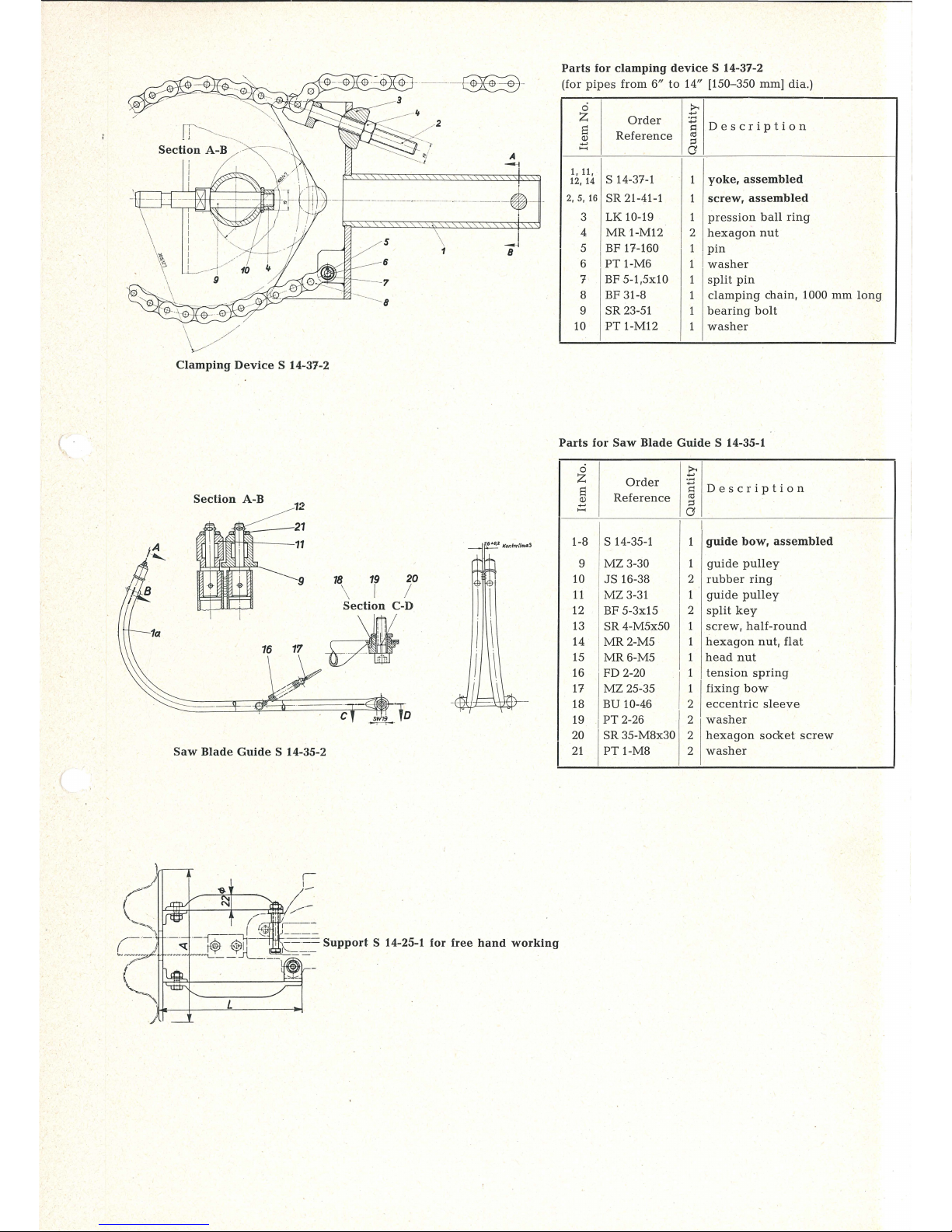
Parts
for
clamping
device
S 14-37-2
(for
pipes
from
6"
to
14" [150-350 mm] dia.)
0
£
z
Order
.....
Descrip
tion
s
.:
Reference
co
~
;:I
a
1, 11,
s 14-37-1
1
yoke,
assembled
12,
14
2, 5,
16
SR
21-41-1
1
screw,
assembled
3
LK 10-19
1
pression
ball
ring
4
MR
l-M12
I
2
hexagon
nut
5 BF 17-160
1
pin
6
PT
1-M6
1
washer
7
BF 5-1,5x10
1
split
pin
8
BF 31-8
1
clamping
chain, 1000
mm
long
9
SR
23-51 1
bearing
bolt
10
PT 1-M
12
1
washer
Clamping
Device
S 14-37-2
(
Parts
for
Saw
Blade
Guide
S 14-35-1
Section
A-B
12
0
.~
z
Order
s
-;:;
Description
Reference
co
~
;:I
a
aTr,--
- 21
rm;rtt-f'rt--
--
11
Is 14-35-1
I
1-8
1
guide
bow,
assembled
9
MZ
3-30
1
guide
pulley
16
18
19
20
\ I I
Section
C-D
-~if
-",..,;..,..,
Saw
Blade
Guide
S 14-35-2
10
JS
16-38 2
rubber
ring
11
MZ
3-31 1
guide
pulle
y
12 BF 5-3x15 2
split
key
13 SR 4-M5x50 1
screw,
half-round
14
MR2-M5
1
hexagon
nut,
flat
15
MR6-M5
1 h
ead
nut
16 FD 2-20
I
1
tension spring
17
MZ
25-35
1
I
fixing
bow
18
BU 10-46 2
eccentric
sleeve
19
1
PT
2-26
2
washer
20
SR
35-M8x30 2 h
exagon
socket screw
.__I
21--'-1 P_T
1--M
8 -----'----'-2 w_ash_er --·J
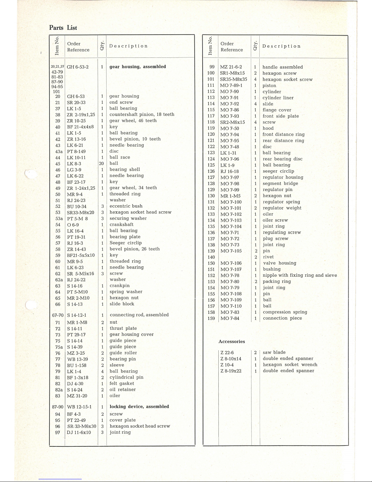
Parts List
0
z
·
Order
:>.
Description
s
a
~
Reference
0
z
Order
:>.
s
a
Description
~
Reference
20,21,37
GH
6-53-2 1
gear
housing,
assembled
99
MZ
21-6-2
1
handle
assembled
42-79
81-83
87-90
100 SR1-M8x15
2
hexagon
screw
101
SR35-M8x35 4
hexagon
socket
screw
94-95
111
MO
7-89-1
1
piston
101
20
GH
6-53
1
gear
housing
21
SR
20-33
1
end
screw
112
MO
7-90
1
cy
linder
113
MO
7-91 1
cylinder
lin
er
114
MO
7-92 4
slide
37
LK 1-5
1
ball bearing
38
ZR 2-19x1,25
1
countershaft
pinron,
18
teeth
115
MO
7-86 1
flange
cover
117
MO
7-93
1
front
side
plate
39
ZR 10-25 1
gear
wheel,
46
teeth
118
SR2-M6x15
4
screw
40
BF 21-4x4x8 1
key
119
MO
7-50
1
hood
41
LK 1-5 1
ball
bearing
120
MO
7-94
1
front
distance
ring
42
ZR 13-16 1
bevel
pinion,
10
teeth
43
LK 6-21 1
needle· bearing
121
MO
7-95 1
rear
distance
ring
122
MO
7-48 1
disc
43a
PT
8-149
1
disc
44
LK 10-11
1
ball
race
45
LK8-3
20
ball
46
LG 3-9
1
bearing
shell
47
LK 6-22
1
needle
bearing
48 BF 23-17
1
key
49
ZR 1-24x1,25
1
gear
whee
l, 34
teeth
50
MR9-4
1
threaded
ring
51
RJ
24-23
washer
52
BU 10-34
3
eccentric
bush
53
SR33-M8x20
3
hexagon
socket
head
screw
53 a
PT 5-M
8
3
securing
washer
123
LK 1-31 1
ba
ll
bearing
124
MO
7-96
1
rear
bearing
disc
125
LK 1-9
1
ball
bearing
126
RJ
16-18
' 1
seeger
circlip
127
MO
7-97 1
regulator
housing
128
MO
7-98 1
segment
bridge
129
MO
7-99
1
regulator
pin
130
MR
1-M5
2
hexagon
nut
131
MO
7-100
1
regulator
spring
132
MO
7-101
2
regulator
weight
133
MO
7-102
1
oiler
134
MO
7-103 1
oiler
screw
54
0 6-9
1
crankshaft
55
LK 16-4
1
ball
bearing
56
PT
19-
31
1
bearing
plate
57
RJ
16-3 1
Seeger
circlip
58
ZR
14-43 1
b
evel pinion,
26 teeth
59
BF21
-5x5x
10
1
key
135
MO
7-104 1
joint
ring
136
MO
7-71 1
regulating
screw
137
M07-72
1
pl
ug
screw
138
MO
7-73
1
joint
ring
139
MO
7-105
2
pin
140 2
rivet
60
MR9-5
1
threaded
ring
61
LK 6-23 1
needle
bearing
150
MO
7-106
1
valve
housing
151
MO
7-107 1
bushing
62
SR
5-M5x16
3
screw
62a
RJ
24-22
washer
63
s 14-16 1
crankpin
64
PT
5-MlO 1
I
spring
washer
65
MR2-M10
1
h
ex
agon
nut
152
MO
7-78
1
nipple
with
fixing
ring and
sieve
153
MO
7-80 2
pack
ing
ring
154
MO
7-79
1
joint
ring
155
MO
7-108
1
pin
156
MO
7-109
1
ball
66
s 14-13 1
slide
block
157
MO
7-110
1
ball
67-70
s 14-12
-1
1
connecting
rod,
assembled
71
MR
1-M8 2
nut
158
MO
7-83 1
compressi.on
spring
159
MO
7-84
1
connection
piece
72
s 14-11 1
thrust
plate
73
PT
29-17 1
gear
housing
cover
75
s 14-14
1
guide piece
Accessories
75a
s 14-39
1
guide
piece
76
MZ
3-25 2
guide
roller
77
WB
13-39 2
bearing
pin
z 22-6
I
2
saw
blade
Z 8-10x14
1
doub
le
ended
.spanner
78 BU 1-158
2
sleeve
z 10-4
1
hexagon
socket
wrench
79 LK 1-4
4
ball
bearing
Z 8-19x22
1
do
uble
ended
spanner
81
BF 1-3x18 2
cy
lindri
cal
pin
82
DJ
4-30
1
felt
gasket
82a
s 14-24 2
oil
retainer
83
MZ
31-20
1
oiler
87-90
WB
12-15-1
1
locking
device,
assembled
94
BF 4-3 2
screw
95
PT
22-49
1
cover
plate
96
SR
;33-M6x30
3
hexagon
socket head scr
ew
97
DJ
11-6x10 3
joint
ring
I

Clamping
Device
S 14-10-1
eve
16
17
18
Clamping
Device
S 14-20-2
Parts
for
clamping
device
S 14-10-1
(for
pipes
up
to
6"
[150 mm])
ci
£
z
Order
-;:;
Descrip
tion
s
Reference
<U
~
;:l
a
1,2,15 s 14-17
1
yoke
3
BU 7-54
1
guide
bush
4
s 14-19
1
tightening
bolt
5,6
I
MZ
19-28-1
1
bow
with
nut
7, 12 BF 30-27-1 2
plate,
assembled
8
BU 1-144
1
spacer
bush
9
RJ
1-88
2
interm
edi•ate
collar
10
BF 2-7x46
2
parallel
pin
11
BU 1-145
2
spacer
sleeve
13
BF 2-7x26
1
distance pin
14
BF 31-3
1
clamping
chain
19-23 T 5-9-1
1
clamping
head, assembled
19
T 5-9
1
clamping
head
20
SR
23-28
1
supporting
pin
21
BF 1-
3x8
1
parallel
pin
22
PT
1-M14
1
washer
23
MR
1-M14
1
hexagon
nut
Parts
for
clamping
device
S 14-20-2
(for
profiles)
ci
£
z
Order
s
-;:;
Descript
ion
R
efe
renc
e
<U
~
;:l
a
1,3,4,25
BU 1-169-1 1
clamping tube,
assembled
2
DJ
1-42
1
felt
ring
5
SR
22-24
1
thrust
spindle
6,24
MZ
19-28-1
1
handle
with
nut
7
BF 3b-5x24
1
parallel
piln
8
PT
35-27
1
protective
cover
9
LK 7-26
1
thrust
bearing
10
s 14-26
1
clamping
lug
11
s 14-27
1
clamping
lug
12
PT
8-114
2
guide
plate
13
SR 1-M12x18
2
hexagon
nut
14 BF
3a-4x25
1
self-locking
dowel
pin
15 BF 3f-8x40
2
toggle
pin
16
SR
1-M6x50
2
hexagon
scr
ew
17
BU 1-147
2
spacer sleeve
18
MR 1-M6
2
hexagon
nut
19-23 T 5-9-1
1
clamping
head,
assembled
(see
under
S 14-10-1)

worn
too
far,
oiler
too
full
or
clogged,
ball
bearings
worn
or
damaged.
Remedies:
check
air
pressure,
clean
motor
with
paraffin
and
lubricate
well.
In ca·
se
of
doubt,
or
if
trouble
persists,
return
machirte
to
the
distributor
for
repair.
The
motor
is
automatically
lubricated
by
the
economy
oiler
built
into
the
handle.
Before
the
start
of
each
working
shift,
Ml
the
oiler
with
thin-flowing
resin-free
machine
oil
(SAE 10).
One
filling
will
last
for
one
normal
working
shift.
Oil
feed
is
easily
re-
gulated. Take
off
enq
screw
cap
to
expose
the
control
screw
,
tighten
screw
to
reduce
oil
feed,
slacken
screw
to
increase
it.
Generally,
half a turn
will
suffice.
Should
the
oiler
become
clog-
ged,
take
out
the
screw,
and
clear
the
bore
which
then
becom
es
visible
with a piece of
wire.
If
the
full
oi'ler
is
connected
to
the
compressed-air
line,
the
oil
must
clearly
be
seen
to
bubble
under
the
pressure
when
the
filler
screw
is
open.
All
sliding
faces
of
the
crankshaft
should
be
lubricated
once
a
week
via
the
ball
oiler
on
the
housing.
It
is
advisable
to
renew
the
gear
grease
approx.
every
300
dut
y
hours. We
recommend
our
proveri
special
gearbox
grease
FG
11.
The
ball
bearings
should
be
cleaned
approx.
every
900
duty
hours
and then
be
repacked
with
fresh
Fein
FK 3 ball
bearing
grease.
To
prevent overheating
of
the
bearings,
fill
only
about
1
/a
of
the
space
between
races.
Correct
grade
and
quantity
of
grease
is
essential
for
good
lubri-
cation
and
to
prevent
damage·
through ove
rheating,
and the
data
given
in
the
table
below
should,
ther
efore, be
adhered to:
Grease
I
Quantity
I
Tubes
Holding
Order No.
approx.
FG
11
for
gearbox
3
1
/2
oz.
MZ
60-3/FG
11
2
3
/4
oz.
100 g
80 g
FG
3 for
bearings
MZ
60-1/FK 3
1
12
oz.
10 g
No
guarantee
claims
can
be
e nt
erta~ne
d
in
respect
of
any dam
-
age
due
to
insufficient
maintenance and
lubrication
.
7.
Dismantling
Machine
Only
by
expert
fitters.
a)
Motor
First
separate
saw head from
motor
by removing the 3
screws
on
the
dri
ve
casing
. N
ext
pri
ze apart
casing
(119)
and
take
.
off
the 4 screws
(118).
Take
off
flanged
cover
(115).
Take
off
governor
housing
(127),
unscrew
from pi.
ston
(111),
complete
governor,
consisting
of
flanged
sleeve
(128),
governor
spindle
(129),
hexagon
nut
(130),
governor
spring
(131),
dowel
pins
(140)
and
governor
weights
(132).
Next, take
out
rear bea
ring
plate
(124)
with
ball
bearing
(125),
circlip
(126) and
rear
spacer .ring
(121).
Slides
(114) will
now
come
away
to
the
rear.
Notched
pins
(1
39)
remain
in cylind
er (112).
Lightly
tap
front
(pinion)
end
of
piston
(111)
against a wooden
base
to
drive
piston
out
to
the
rear.
Take
off
from
the
front
bearing
plate
(122)
with
ball
bear
-
ing
(123),
front
side
plat
e (117)
and
front
spacer
ring
(120).
Tak
e
end
scr,ew
cap
(159)
and
nipple (152)
off the
valve,
taki
ng
care
not
to
lose
the
compression
springs
(158)
which
may
snap
away
if
not
held
. Balls (156
and
157)
are
now
loose
and
will
drop
out
of
valve
hou
sin
g (150).
Pull
rotary sl
eeve
(151)
from
valv
e
housing,
then
un~crew
housing
from
oiler
(133).
Unscrew oiler
from
governor
housing
(127).
b)
Drive
and
Push
Rod
Take
off gears
(39)
and
(38), then
slacken the 3
socket-head
screws
(53)
and take
off,
to
the
front, bevel
gear
(42) with thre
ad-
ed
ring
(50),
gear
(49),
bearing
sleeve
(46),
needle
bear
ing
(47),
ball
race
(44),
balls
(45)
and
needle
bearing
(43),
comple
te
wit
h
their
washers.
Next, take
off
gearbox cover
(73).
Locating
guides
(75
and
75a)
can
easily
be
driven
out from
the
opposite
sid
e.
Drive
out
pins
(81),
then
tak
e off
bearing trunnion
pins
(77),
ball
bearing
(79),
sle
eves
(78)
and
guide
rollers
(76).
Now pull
out
to
the
top
drive
arm (69)
with
gate
(67).
Take
care
not
to
lose felt
washer
(82)
and
scraper
(82a).
Sliding
shoe
(66)
lies
loosely in
gate
(67). After
slackening
hexagon nut
(65),
the
crankpin
(63)
can
be
pushed
out
of
crankshaft
(54)
.
Next take
off
the three
countersunk
screws
(62)
and
pull
off
bearing
plate
(56)
with
shouldered
bearing
(55),
circlip
(57),
crankshaft
(54) b
evel
gear (58)
and
thr
eaded
ring
(60).
To
dis-
mantle
these
parts
further,
take
off
ring
(60).
Take
care
not
to
lose
washers
(62a).
Assembly
Assemble
in reverse seq
uenc
e,
taking care
that
front
side
plate
(117)
and
rear
bearing
plat
e (124)
are
correctly
locat
ed
in
rela-
tion
to the cy
linder (notched
pins
139
must
engage
in
their
mat-
i
ng
bores)
and
do
not
forget
felt .washer
(82)
and
scraper
(82a).
Setting
Governor
The
secondary-air
speed
governor
works
on
the
centrifugal
force
principle.
Depending
on
the
setting
of the
spring,
the
we
ights
will
swing
outwards
to a greater
or
less
er
degree.
To
set
the
governor, unscrew
it
from
piston
(111),
then
turn
the
two
hexagon
nuts
on
the
governor
spi
ndle
to
adjust
the
spring
force
as
follows:
unload
spring
('/2
to 1 turn
of
nut)
to
reduce
strok
ing
rate
tight
en
spring
(112
to 1 turn
in
opposite
direction)
to
increa
se
stroking
rate
At a service
pressure
of
87
lbs
./sq
. in.
(6
atm.),
the
unlo
ade
d
saw
blade
should
stroke
at
the
rate
of
360/min.
To
check,
take
off
screw
cap
(21)
at
top
of
gearbo
x,
and
then
measure crank-
s
haft
(54) revolut
ions,
which
equals
working
strokes,
at the
c
rankshaft
end
now expos
ed.
Setting
Bevel
Gears
To
correct
bevel
gear
backlash,
slacken
the
three
socket-head
screws
(53),
then
turn
ecce
ntric
flanged
bush
(52)
to
set
correct
play;
finally
tight
en
the
screws
again
fir
mly.
(
 Loading...