


(
DSk
658
To be handed to the workshop!
Operating instructions
for the Two
Speed Electric Drill type DSk
658
and for DSk
758
(42
Volts)
and for DSke
658
(with electronic
sp~ed
control)
1.
Technical
data
Type
of
current: ~ AC
single
phase
Internal
fuses
for
220
Volts:
10 A (slow)
or
15
A (fast)
Capacity
in
steel
Speed
R.
P.M
.
Morse
Taper
Net
Type
Input
I
Output
Socket
of
weight
in
.
I
mm
full
load I no
load
Watts
Watts
spindle
lbs
I
kg
DSk
658 l
'/,/3/4
13/19 420/200 720/340
540 320
2
13,42 6,1
DSk
758
{42
V)
DSke
658
1
/2fl/4
13/19
240-420/
330-720/
540 320
2
14,1
6,4
I
110-200
:l.
Construction
The
two
speed
hand
drill
DSk
658
is
an
electric
tool
of
Class
II
with
protective
insulation
according
to
VDE
regulations
0740.
The
protective
insulation
is
additional
to
the
normal
insulation
and
separates
all
accessible
parts
of
the
metal
casing
from
all
internal
parts
liable
to
become
live
.
The
machine
must
not
be
earthed
and
must
be
connected
with
a
two-core
cable
without
earth
wire.
The
drill
is
tested
with
the
prescribed
test
voltage
of
4000 V.
The
machin
e is
radio
suppressed
according
to
radio
interference
VDE 0875.
Type
DSk
758,
for
low
tension
(42 V)
is
of
the
same
design,
but
without
double
insulation.
To
prevent
the
overbridging
of
the
insulation
no
additional
marking
plates
and
signs
must
be
riveted
or
screwed
on
the
housing.
We
recommend
the
use
of
transfers
only.
BE 209/e X
1.
73
Printed
in
Germany
150-340
3.
Connection
and
operation
Main
voltage
must
correspond
to
the
operating
voltage
marked
on
the
rating
plate.
The
tool
can
be
plugged
into
plain
or
safet
y
sockets.
Switch
must
be
in
the
"Off"
position
when
connecting.
The
speed
of
the
machine
must
only
be
changed
at
stand-still
or
at
slowing
down
without
load. Release
switch
handle
(47)
of
its
longitudinal
position,
put
it
across
by
turning
it
out,
then
push
it
into
the
wanted
switch
direction
and
reset
the
switch
handle
in
opposite
direction
again
into
its
longitudinal
position.
The
type
DSke
658
has
an
electronic
speed
control.
The
speed
will
be
changed
by
turning
the
button
situated
on
the
handle,
when
the
machine
is
running
or
not.
The
speed
will
be
increased
by
turning
the
button
clockwise
and
reduced
by
turning
it
anticlockwise
.

·,-
0@
T
I
r - ; 1
~ar~~
a
52-~~
7
50
~
310 '[
~
--r'?"'--
32 33
34
36
37
~
•lli+B
a m ·1. - 8
1-110
I I I - I
40
38
39
41
61
I 0
el)
0
8
e) 0
e)
........,
0
I I
________________________________
,.
___
62_
_______ §.;i
______________________________________
,.
______________________________________________
.._
___________
_
1:
t
l
____
g
II
~
,
--
59
5857
15
~
I I I
6 2 - 3
--
ic---i--
----------------)>-------------------------------------------------------------)>-------------------------------------------)>------------
-,
' -------
~
-
~~
•
1111
77
I
I~
74
-
!JJJ
~
llll
J
J
JJJJJJJ
60
- [
__
•
__
/
~=
==
::
-----~
-
10
78 i
, I
@=C
llllill
llllill:ll
llll
--
~
-------
~~····,
~
,,
~
!
64
-T
,,
r
......_.,
!
:
I
'
- ' -
EZ
1-7~
220V~
Wiring
diagram
-
only
for
DSke
658
b
a
b
b
b
b
.
0
z
Order
;;..
....,
....
Reference
5
r;j
P-<
I
1-13
MK
3-101-2
1
)
1
1-14
MK
3-101-8
1
)
1
1
MK
3-101
1
2, 3
MK
13-17-1
1
2
MK
13-17
1
3
EZ
12-50
2
4
SR
2-M5x15
2
5
PT
5d-M5
2
6
state type
1
and volta
ge
7
SR 1-M4x60
2
8
PT
37-13
2
10
EZ 11-70
I
2
11'
12
PT
27-3'i'-1
2
13
SR
2-M4x12
4
15-20
sta
te
type
1
and
voltage
20
FL 4-2-1
1
21-52
LA
8-116-2
1
21
LA
6-169
1
22-52
LA
8-116
-1
1
22
LA
8-1 16
1
25
BF 1-4x15
1
26
WB
2-38
1
27
RJ
12-50
1
28
LK 13-9
1
29
PT
8-164
1
29a
PT
8-175
1
30
DJ
1-61
1
31
PT
8-173 1
32
DJ
1-60
1
32a
PT
11-67 1
33
LK 16-16
1
34
PT
8-168 1
35
BF
21-5x5x10 1
36
ZR
15-12x1,25
1
37
MR
3-M1
4xl,5
1
38
ZR 16-
9x
1 1
39
ZR
15-32x0,
75
1
40 LK 1-3 2
41
LK 1-3 2
42
ZR
16-5x1,25
1
43 BF 21-6x6x36
1
44
ZR
15-27x1 1
45
RJ
16-9 1
46
BF17-
186 1
47-51
SA
5-52-1 1
47
SA
5-52
1
48
FD
1-202 1
49 BF 16-86 1
50
BF 17-191
1
51 BF 38-2x12 1
52
BF
38-3x
16
1
56
LK 1-3
1
57
LK 16-30
1
58
RJ
12-57
1
59
JS
6-28
1
60
SR
33-M5x25
4
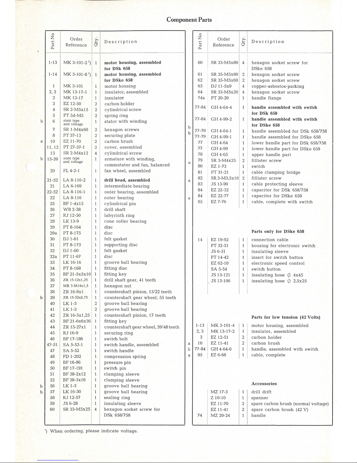
Component Parts
Description
motor
housing,
assembled
for
DSk
658
motor
housing,
assembled
for
DSke
658
motor
housing
insulator,
assembled
insulator
carbon
holder
cy
lindrical
screw
spring
ring
stator
with
winding
hexagon
screws
securing
plate
carbon
brush
cover,
assembled
cy
lindrical
screw
armature
with winding,
commutator
and
fan,
balanced
fan
wheel,
assembled
drill
head,
assembled
intermediate
bearing
outer bear
ing,
assembled
outer
bearing
cylindrical
pin
drill
shaft
labyrinth
ring
cone
roller
bearing
di:sc
dis
c
felt
gasket
supporting
disc
felt
gasket
disc
groove
ball
bearing
fitting
disc
fitting
key
drill
shaft
gear,
41
teeth
h
exa
gon
nut
countershaft
pinion,
13/22
teeth
countershaft
gear
wheel,
55
teeth
groove
ball
bearing
groove
ball
bearing
countershaft
pinion,
17
teeth
fitting
key
countershaft gear
wheel,
39/48
teeth
sec
uring
ring
switch
bolt
switch
handle,
assembled
switch
handle
compression
spring
pressure pin
switch
pin
clamping
sleeve
clamping slee
ve
groove
ball
bearing
groove
ball
bearing
sealing
ring
insulating
sleeve
h
exag
on
socket
screw
for
DSk
658/758
b
b
a
a
a
a
b
a
0
z
Order
;;..
....,
5
....
Reference
co
P-<
60
I
SR 33-M5x80 1 4 1
61
, SR 35-M5x80
2
62
SR 35-M5x60 2
63
DJ 11-5x9 4
64
SR 33-M5x20 4
74a
PT
20-20
1
77-84
GH4
-64-4
1
77-84
GH
4-99-2
1
77-79
GH
4-64-1
1
77-79
GH
4-99-1
1
77
GH
4-64
1
77
GH4-99
1
78
GH
4-65
1
79
SR
3-M4x25
2
80
EZ 1-73
1
81
PT
31-21
1
82
SR3
-M3,5x 10
2
83
JS
13-90
1
84 EZ 22-32
1
84
EZ
22-77
1
85
EZ
7-76
1
I
14 EZ 19-92
1
PT
32-51
1
JS
6-31
1
PT
14-42
1
EZ
62- 10
1
SA
5-54
1
JS
13-121
1
JS
13-106
1
1-13
MK
3-101-4
1
2,3
MK
13-17-2
1
3 EZ 12-5 1
2
10
EZ 11-41
2
77-84
GH
4-64-6
1
85 EZ 6-68
1
MZ
17-3
1
z 10-10
1
EZ11-70
2
EZ 11-41
2
74
MZ
20-24 1
1
)
When
ordering,
please
indicate
voltage.
Description
hex
agon
socket
screw
for
DSke
658
h
exagon
socket
screw
hexa
gon
socket
screw
coppe
r-asbesto
s-packing
hexa
gon
socket
screw
hand
le
flange
handle
assembled
with
switch
for
DSk
658
handle
assembled
with
switch
for
DSke
658
ha
ndle
assembled
for
DSk
658/758
handle
assembled
for
DSke
658
low
er
handle
part
for
DSk
658/758
lower
handle
part
for DSke
658
upper
handle
part
fillister
screw
switch
cable
clamping
bridge
fillist
er
screw
cable
protecting
sleeve
capa
citor
for
DSk
658/758
c
apacitor
for
DSk
e 658
cable,
complete
with
switch
Parts
only
for
DSke
658
connection
cable
housing
for
electronic
switch
insu
lating
sleeve
insert
for
switch
button
electronic
speed
control
swi
tch
button
insulating
hose
q;
4x45
insu
lating
hose
q;
2,
5x25
Parts
for
low
tension
(42
Volts)
motor
housing,
assembled
insulator,
assembl
ed
carbon
holder
carbon
brush
handle,
assembled
with
switch
cable,
complete
Accessories
drill
drift
spanner
spare
carbon
brush
(normal
voltage)
spare
carbon
brush
(42 V)
ha
ndle

4.
Maintenance
and
lubrication
Before
carrying
out
any
maintenance
work
always
remember
to
pul~
out
the
plug.
After
300
working
hours
clean
air
openings
of
the
motor
housing.
Blow
out
motor
with
dry
pneumatic
air.
Renew
the
gear
grease.
Only
use
the
Fein
special
grease
Sst
1.
Worn
carbon
brushes
automatically
switch
off
the
machine
after
reaching
their
minimum
length.
After
checking
the
carbon
brushes
make
sure
to
refit
them
in
their
original
position
and
check
that
they
move
easily
in
their
holder.
After
fitting
new
brushes,
run
tool
unloaded
for
about
15
minutes
to
allow
brushes
to
bed
in.
Please,
only
use
original
Fein
carbon
brushes.
In
order
to
prevent
accidents
check
cable
and
connections
at
both
sides
at
regular
intervals.
Use
only
Fein
special
grease
Sst
1.
Quantity of
grease
120 g.
The
order
reference
for a tube
of
approx.
180
giis
MZ 60-4/Sst 1.
After
900
duty
hours
the
machine
should
be
completely
dis
-
mantled
as
described
under
paragraph 6 and
all
parts
should
be
thoroughly
cleaned.
Rinse
ball
bearings
and
gears
in
clean
solvent
and
pack
with
grease
Sst
1.
The
space· between
inner
and
outer
ring
is
to
be
one
third
filled
with
grease
in
order
that
the
bearings
do
not
overheat.
Please
be
sure
that
all
electric
and
plastic
parts
are
only
cleaned
dry.
For
good
and
adequa
te
lubrication
and
to
avoid
overheating,
it
is
important
to
pack
gearing
and
bearings
with
the
grades
and
quantities
of
grease
indicated.
No
claims
can
be
entertained
for
damage
due
to
negligent
main-
tenance
and
inadequate
lubrication.
5.
Dismantling
The
tool
should
only
be
taken
apart
by
an
expert.
1.
Pull
plug
from
socket.
2.
Take
off
motor
housing
cover
(11),
take
out
carbon
brushes
(10).
3.
Take
off
handle
cover
(78),
loosen
supply cable
and
interior
connection
cable
from
switch
(80). Take out
switch
and
clamp
off
cab
le
(85)
together
with
protecting
sleeve
(83)
from
clamping
bridge
(81).
4.
Remove
lower
handle
section
(77),
draw
out
insulation
sleeve
(59).
For
the
type
DSke
658:
take
off
the
lower
part
of
the
handle
.
Loose
the
soldering
part
between
the
black
connecting
cable
of
the
electronic
speed
control and
the
cable
of
the
pole
housing
and
between
the
protection cab
le
(b)
of
the
capacitor
and
the
connection
cable.
Take
off
the
housing with
the
electronic
speed
control.
5.
Unscrew
two
screws
from
61
and
from
62,
take out
bear
ing
(2
2),
intermedia
te
bearing (21) with
armature
(15)
of mot
or
housing
(1),
push
out
armature
(15)
togeth
er
with wheel
and
ball
bearing
(20
and
57)
out
of
intermediate
bearing
(21).
6.
Push
out
the
clam
ping
sleeve
(52)
of
shift-bolt
(46) by
means
of
a 3
mm
pin
in
direction
of
boring
shaft,
pull
out
sw itch
handle
(47) with
switch
pin
(50)
at
the
side.
Remo
ve switch
bolt
(46)
and pay
attention
to the
easily
accessib
le
clamping
slee
ves
(52).
7.
Draw
countershafts
(38)
and
(42) out
of
outer
bearing
(22).
8.
Unscrew hex
agon
nut
(37), dr
aw
off
drill
shaft
gear wheel
(36),
take
out
fitting
key
(35), push out
drill
shaft
(26)
.
Pay
attention
to
washers!
9.
Only
in
case
of
damage,
take
out insulator
(2) with stat
or
(6)
after
pulling supply cable through
the lateral bor
ing
into
the
housing
and
unscrewi
ng
fillister
head
screws with
slots
(4).
Re-assemble
in
reverse
sequence.
We
supply
special keys
ZSo 29-2-1
for
the
assemb
ly
of the
contact
spring
tools
of the
car
bon
brushes.
6.
Stationary
use
in
the
bench
drill stand:
If
the
machine
remains
in
the
bench
drill
stand,
the
gear
grease
is
not
sufficiently changed,
that
is
why
it
must
be
regreas-
ed
once a week
with
the
grease
gun.
The
grease
pins
el
lies
in
the
intermediate
bearing
(21).
After
operation
do
not
keep the
magnetic
bench
drill
stand with
the
fixed
machines
in a ve
rtical
position,
but
in a horizon
tal
one
so
that
the
gear
grease
is
distrib
uted equally.
7.
Repair
and
Spare
Parts
We
recommend
our Fe
in Servic
e S
tations to
carry out
all
over-
haul
and
repair work
quickly
and
expertly
.
Please
quote
Order
Reference
when
ordering
spare
parts or
send
in
sample
part, stating
the
type
of
the
machine.
We
draw
your
attention
to
the
need
to
carry out
a h i
gh
volta
ge
test
in
accordance with
your
loc
al
regulations
(or
VDE
regu-
la
tion
0740) b
efore taking a tool into
service
after any repair
ca
rri
ed
out
by your
own
staff.
(
 Loading...