

(
To
be
handed
to
the
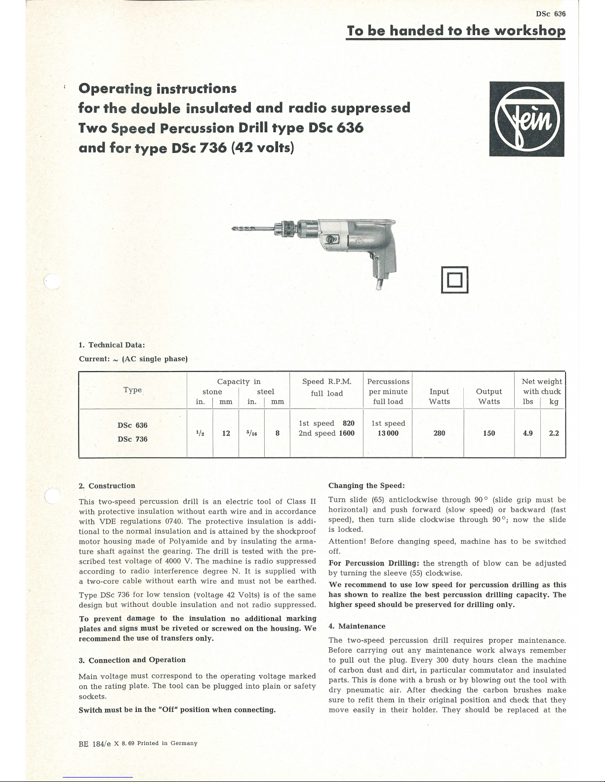
Operating
instructions
for
the
double
insulated
and
radio
suppressed
Two
Speed
Percussion
Drill
type
DSc
636
and
for
type
DSc
736
(42
volts)
1.
Technical
Data:
Current: -(AC
single
phase)
I
Capacity
in
Speed
R.P.M .
Percussions
Net
weight
I
Ty
pe
stone
I
steel
full loa
d
per minute
Input
I
Out
put
with
chuck
in
. I
mm
in. I mm
full
load
Watt
s
Watts
lbs I kg
DSc
636
1st
speed
820
1st
speed
1f2
12
5
/16
8
2nd
spe
ed 1600
13000
280
150
4.9 2.2
DSc
736
2.
Construction
This
two-speed
percussion
drill
is
an
electric
tool
of
Class
II
with
protective
insulation
without
earth
wire
and
in
accordance
with
VDE regulations
0740.
The pro
tective
insulation
is
addi-
tional
to
the
normal
insulation
and
is
attained
by
the
shockproof
motor housing
made of
Polyamide
and
by
insulating the
anna-
ture shaft
aga
inst the
gearing.
The
drill
is
tested
with the
pre-
sc
rib
ed test voltage of
4000 V.
The
machine
is
radio
suppressed
according
to radio
interference
degree
N.
It
is
supplied
with
a
two-core
cable
without
earth
wire
and
must
not
be
earth
ed.
Type
DSc
736
for
low
tension (volt
age 42
Volts)
is
of
the
sam
e
design
but without
double
insulati
on
and
not
radio
suppressed.
To
prevent
damage
to
the
insulation
no
additional
marking
plates
and
signs
must
be
riveted
or
screwed
on
the
housing.
We
recommend
the
use
of
transfers
only.
3.
Connection
and
Operation
Main
voltage
must
correspond
to the
operating
voltage
marked
on the
rating
plate.
The
tool
can
be
plugged
into plain or
safety
sockets.
Switch
must
be
in
the
"Off"
position
when
connecting
_
BE 184/e X
8. 69
Printed
in
Germany
Changing
the
Speed
:
Turn
slide
(65)
anticlockwise through
90 °
(slide
grip
must
be
horizontal)
and
push
forward
(slow
speed) or
backward
(fast
speed). then turn
slide clockw
ise
through
90 ° ;
now
the
slide
is locke
d.
Attention
! Be
fore cha
nging
spee
d, mac
hin
e h
as
to
be switched
off
.
For
Percussion
Drilling:
the
strength
of
blow
can
be
adjust
ed
by
turning
the
sleeve
(55)
clockwise
:
We
recommend
to
use
low
speed
for
percussion
drilling
as
this
has
shown
to
realize
the
best
percussion
drilling
capacity.
The
higher
speed
should
be
preserved
for
drilling
onl
y.
4.
Maintenance
Th
e t
wo-spee
d p
ercussion
drill
requires
proper maint
enance.
Before
carrying
out
any
maintenance
WC?rk always remember
to
pull
out
the
plug. Eve
ry 300
duty
hours
clean the
machine
of
carbon
dust
and
dirt,
in
particular
commutator
and
insulated
parts.
This
is
done
with a brush or
by
blo
wing out
th e
tool with
dry pn
euma
tic
air.
After
checki
ng the
carbon brush
es
make
sure
to
ref
it them
in
the
ir original
position
and
check that
th ey
move
easily
in
their holder. They
should
be replaced
at
the

56
57
58
44
46 47
48
49
59-Y
59
a--~
59b~
®
I I I I 52
53
40 y
I
0 0 0 ce I £
~
• • o
aiD)
11
~
l •
0-1
I "
_______
,...
____
_.
~--
·
·------------------------
I
~~
~
-
_ r
.I
,3:",. , __
74
.
~,
"~"
r _ ..
-A
34
L.
'
d1it
---rtl--~
u-
---
.... ,
37
43
I I I
LO
63
-
-
fiQ---r~-64
r----------------------
··,
---------
1 . p
6s
~
'lf
~
l • .
~
I
~
---
~
_ _.. _..
I
....... ---··· . ..
____
.. •
'-
.
""
.
L-_.
®)
I
~~
~
~
01
:
_
___
_ , 1 ,
~
-
r' .
~
1
~1~
_13--
;""f!J
33
__
if
.......
26
8
------
..
___
...,
,~'~
.,
30 •
---
1 ;
...
__
...
/
34
a33
31
32
-----~-
j I
~
• ,
__ ,·::
..
;(
~
~
J""'
~f'
5
~
9
..
· I
__..
./
1
.--
~
·
1o
_..
I
--
--
1
..
I
I
I
I
_,?
I
~"'
._..,~
-·
15
~
24
~~
11
-,
~

-.
Component Parts
'
Part
No
Order
.b
Description
Reference
a
Part
No
Order
>.
D e
scription
Reference
a
1-25
MK
1-15-2
. 1
motor
housing,
assembled
48
FD
1-184
1
compression
spring
1-15
MK
1-15-1
1
motor
housing,
assembled
1
MK
1-15
1
motor
housing
2 EZ 1-58
1
switch
49 A 2-52
1 a
dj
usting
ring
52 BF 16-80
1 p
in
53 FD 1-198
1
compression
spring
3 EZ 22-34
1
capacitor
4
SR3-M3,5x6
1
fillister
head
screw
5
EZ 12-43-1
1
2
carbon
holder,
assembled
8
EZ 11-59 2
ca
rbon
brush
9
EZ 13-8 2
sliding
cover
10
SR2-M3,5x12
4
cylindrical
screw
11
BF 19-42-1
1
locking
pin
12
state
type
1
pole
housing
with
winding
and
voltage
13
PT6-M3,5
2
securing
plate
14
SR
2-M3,5x50 . 2
cylindrical
screw
15
JS
28-4
1
insulation
ring
16
EZ
7-101
1
c
abl
e
54
DJ
12-3
1
ri
ng
55
BU 4-63
1
sleeve
56
DJ
1-51
1 f
elt ring
57
LK 15-6
1 nee
dle bearing
58
RJ 15-84
1 retai
ning
ring
59
SR
14-33 2
countersunk
screw
59 a
JS
19-21
2 r
ing
59b
PT 5d-M 5
2
securing
plate
60
ZR15-20x0,75
1 s
lide
gear
wheel,
40/33
teeth
61
ZR16-13x0,75 1
pinion,
10/16
teeth
61a
PT
8-153
1 d
riv
ing
plate
62 ZR15-22x0,75
1 g
ear
whe
el, 30 teet
h
63 BF 17-168
1
s
witch bolt
17
JS
13-7
I 1
cable
protecting sleeve
18
PT 31-
21
I
~
cable clamping
bridge
19 SR 3-M3,5x10
fillister
head
screw
20-23
GH
1-18-1
1
cover
with
spare
carbon
brushes
24
SR2-M3,5x15
2
cylindrical
screw
25
SR6k-M3,5x8
1
fillister
countersunk
screw
26
s
tate type
1
armature with
winding
I
a
nd volt
age
commutator
and
fan
30
ZR 4-42
1
pinion, 6 tee
th
31
SR
2-M
3,5
x6
3
cy
lind
ric
al screw
32
PT 5d-M3,5
3
s
ec
uring plat
e
64
FD 7-31
1
lo
ck
spring
65
A9-
53
1
trigger
67
LG4-5
1
bearing
support
68
SR
2-M3,5x10
2
cy
lindrical
screw
69
LK 6a-11
1
needle
cage
70
SR2-M3,5x55
2 cy
lindrical
screw
71
S
R)3
-M3,5x65
2
cy
lindrical
screw
72
PT6-M3,5
4
spring w a
sher
73
BF 1-4x18
1
cy
li
ndric
al
pin
74
MZ 3
1-1
1
gr
ease
nippl
e
33
LK 16-35
2
groove
ball
bearing
34a
RJ
12-56
1
sealing
ring
42
Volts
34-69
LA
8-105-3
1
drill
head,
assembled
3
4,
67-69,
LA
6-150-1
1
intermediat
e b e
aring,
assembl
ed
73
36-69, 74
LA
8-105-2
1
out
er
bearing,
assembl
ed
1-25
I
MK
1-15-6
! i I
mo
tor
housing,
assembled
1-15 MK 1-15-5 motor
housing,
ass
'embl
ed
16
EZ 6-126
cable
36-41, 74
LA
8-105-1
1
o
ut
er be
aring,
assembl
ed
34 LA
6-150
1
intermediate bearing
Accessories
43
LK 1-1
1
groo
ve
ball
bearing
44
WB
3-33
1
drill
shaft
MZ
7-34 1
3-jaw
geared
dmd<:
45
A 2-41
1
cam
ring
46
LK 15-4
1
needle
bearing
MZ57-2
1 key
Z
7-SW
17 S 1
s
panner
47
PT
15-39
1
pressure plat
e
L
___
latest
when
they
have
worn
down
to 7 mm
(1/4'').
Please,
only
use
original
Fein
carbon
brushes.
After
fitting
new
brushes
run
tool
unloaded
for
about
15
minutes
to
allow
brushes
to
bed in.
One
pair
of
spare
carbon
brushes
will
be
found
in
the
cover
of
the
handl
e,
please,
do
not
forget
to
reorder
them
in
time.
In
order
to
prevent
accidents
check
cable
at reg
ular
intervals
.
To
replace
the
cable
take
off
the
screws
(24, 25),
then
take
off
the
handle
cover
(20).
loosen
the
two
screws
(19)
of
the
terminal
clamp
(18)
and
clamp
off
the
cable
from
the
switch
(2).
5. Lubrication
The
percussion
mechanism
should
be
greased
twice a week
by
a
greaser
through
the
grease
nipple
(74).
We
recommend
to
renew
the
gear
grease
after
300
duty
hours
.
Please,
only
use
the
Fein
special
grease FG
12.
For
ball
bearings
wh
ich
should
be
lubricated
after
approx
. 900
duty
hours
we
re-
commend
our
ball
bearing
grease
FK
3.
The
ball
bearings
are
to
be
rinsed
in
clean
solvent
and
packed
with
new
grease.
The
space
between
inner and outer ring
is
to
be
one
third filled
with
grease
in order
to
prevent
that
the
bearings do
not
over-
iteat.
Type
of
grease
Quantity
Order
Reference
Contents
,oz
I
g
oz
I
g
~
for
gearing
2/ 3
I
~
MZ
60-
3/FG
12 2
2
/3
80
.,_5
~
or
ball
- -
MZ
60-2/
FK
3
1
/3
40
bearings
I
No
claims
can
be
entertained
for
damage
due
to
negligent
main-
tenance
and
inadequate
lubrication.
6.
Overhaul
After
900
duty
hours
the
machine should
be
compl
ete
ly
dis-
mantled
as
described
under
paragraph 7 and
all
parts
should
be
thoroughly
cleaned.
Rinse
ball
bearings
and
gears
in
clean
solvent
and
pack
with
fresh
grease
as
per
paragraph
5.
Please
be
sure that
all
electric
parts are
only
cleaned
dry.
'
U
se
U
niversal
Gre:-.sc
typ
e S
st
1
In
stead
of
ot
er
typ8<>
of
g r
ease
I
__
_..
·
-·
7.
Dismantling
The
tool
should
only be
taken
apart
by
an
expert.
1.
Unscrew
fillister
head
screw
(25)
and
the
two cylindrical
screws
(24).
then
take
off
handle
cover
(20).
2.
Remove
supply
cable
from
switch
, draw
out
switch
and
dis-
connect
motor
cable.
After unscrewing the
screws
(10)
draw
out
carbon
holder
(5),
unscrew
screw
(4)
and
pull
out
radio
inte
rference
capacitor
(3).
3.
Unscrew
cylindrical
screws
(70)
and (71)
and
remo
ve
outer
bearing
(36)
with
intermediate
bearing
(34).
4.
Take
apart
outer
bearing
(36)
and,
only
if
necessary,
the
speed-changing
mechanism
in
the
following
manner:
Draw
spring
(64)
out
of
switch
bolt
(63),
then
drigger
(65)
out
of
switch
bolt
(63),
unscrew countersunk
screw
(59) and
pull
out
drill
shaft
with
percussion
head,
loosen
chuck.
Draw
off
sleeve
(55)
and
go
on
taking
apart
percussion
head
.
5.
Pull out
armature
(26).
unscrew
the
three
screws
(31)
and
remove
armature
drive
(30).
6.
Draw
insulation
ring
(15)
out
of motor housing
(1).
unscrew
-
cylindrical
screws
(14)
and
remove
pole
housing
(12)
. .{
Re-assemble
in
reverse
sequence.
All
screws
must
be
tightly
fastened.
In o
rder
to
secure
the two
countersunk
screws
(59)
additionally
use
Loctite, the
fluid
secur-
ing
agent.
Before
applying
this
agent
clean
the
parts
of
all
grease.
8.
Repair
and
spare parts
We
recommend
our
Fein
Service
Stations
to
carry
out
all
over
-
haul
and
repair
work
quickly
and
expertly.
Please
quote
Order Reference
when
ordering
spare
parts
or
send
in
sample
part, quoting the
type
of
the
machine.
We
draw
your
attention
to
the
need
to
carry
out a high
voltage
test in
accordance
with your
local
regulations
(or VDE
regu-
lation
0740)
before
taking a tool
into
serviCe
after
any repair
carr
ied
out
by
your
own
staff.
(
 Loading...