

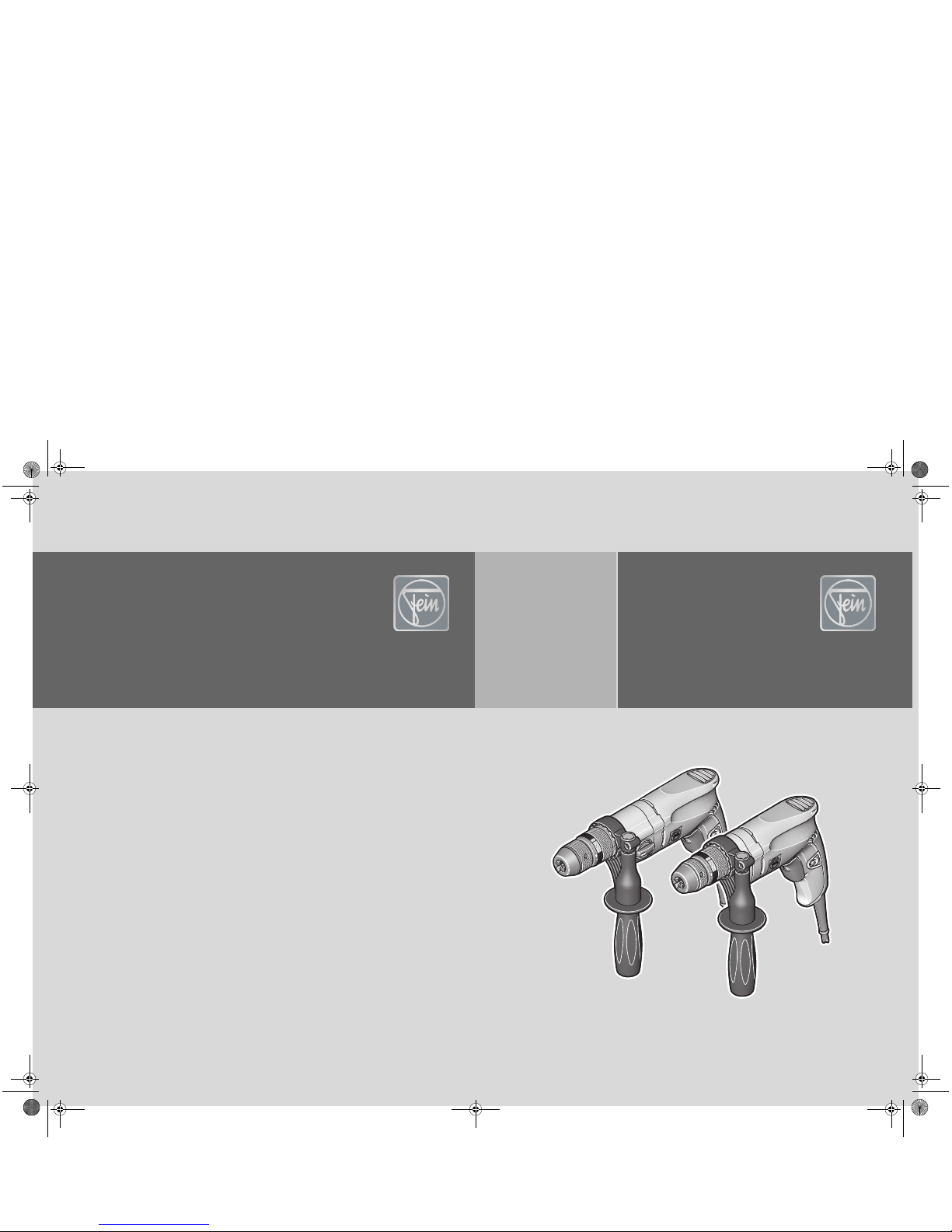
Fein BOP6 Series, BOP10 Series, BOP13-2 Series, BOP10-2 Series Instruction Manual
© C. & E. Fein GmbH. Printed in Germany. Abbildungen unverbindlich. Technische Änderungen vorbehalten. 3 41 01 235 21 0 BY 2015.07 DE.
FEIN Service
USA
FEIN Power Tools Inc.
1000 Omega Drive
Suite 1180
Pittsburgh, PA 15205
Telephone: (412) 922-8886
Toll Free: 1-800-441-9878
www.feinus.com
Canada
FEIN Canadian Power Tool
Company
323 Traders Boulevard East
Mississauga, Ontario L4Z 2E5
Telephone.: (905) 8901390
Toll Free: 1-800-265-2581
FEIN Canadian Power Tool
Company
2810 De Miniac
St. Laurent, Quebec H4S 1K9
Telephone: (514) 331-7390
Toll Free: 1-800-789-8181
www.fein.com
Headquarter
C. & E. Fein GmbH
Hans-Fein-Straße 81
D-73529 Schwäbisch Gmünd-Bargau
www.fein.com
BOP6 (**) 7 205 ...
BOP10 (**) 7 205 ...
BOP10-2 (**) 7 205 ...
BOP13-2 (**) 7 205 ...
OBJ_DOKU-0000005362-001.fm Page 1 Tuesday, July 21, 2015 8:41 AM

2
Instruction Manual
Mode d'emploi
Instrucciones de uso
en
3
fr
19
es
36
OBJ_BUCH-0000000221-001.book Page 2 Tuesday, July 21, 2015 8:42 AM
3
en
en
For your safety.
Read all safety warnings and
all instructions. Failure to fol-
low the warnings and instructions may result
in electric shock, fire and/or serious injury.
Save all warnings and instructions for futurereference.
Do not use this power tool before you
have thoroughly read and completely
understood this Instruction Manual, including
the figures, specifications, safety regulations
and the signs indicating DANGER, WARNING and CAUTION.
Only carry out such operations with this
power tool as intended for by FEIN. Only use
application tools and accessories that have
been released by FEIN.
Please also observe the relevant national
industrial safety regulations.
Non-observance of the safety instructions in
the said documentation can lead to an electric
shock, burns and/or severe injuries.
This Instruction Manual should be kept for
later use and enclosed with the power tool,
should it be passed on or sold.
SAVE THESE INSTRUCTIONS.
The term “power tool” in the warnings refers
to your mains-operated (corded) power tool
or battery operated (cordless) power tool.
General safety rules.
1) Work area safety
a)Keep work area clean and well lit. Clut-
tered or dark areas invite accidents.
b)Do not operate power tools in explosive
atmospheres, such as in the presence of
flammable liquids, gases or dust. Power
tools create sparks which may ignite the
dust or fumes.
c) Keep children and bystanders away
while operating a power tool. Distrac-
tion can cause you to lose control.
2) Electrical safety
a)Power tool plugs must match the outlet.
Never modify the plug in any way. Do not
use any adapter plugs with earthed
(grounded) power tools. Unmodified
plugs and matching outlets will reduce
risk of electric shock.
b)Avoid body contact with earthed or
grounded surfaces such as pipes, radiators, ranges and refrigerators. There is
an increased risk of electric shock if
your body is earthed or grounded.
c) Do not expose power tools to rain or wet
conditions. Water entering a power
tool will increase the risk of electric
shock.
d)Do not abuse the cord. Never use the
cord for carrying, pulling or unplugging
the power tool. Keep cord away from
heat, oil, sharp edges or moving parts.
Damaged or entangled cords increase
the risk of electric shock.
e) When operating a power tool outdoors,
use an extension cord suitable for outdoor use. Use of a cord suitable for out-
door use reduces the risk of electric
shock.
f) If operating a power tool in a damp loca-
tion is unavoidable, use a ground fault
circuit interrupter (GFCI) protected supply. Use of an GFCI reduces the risk of
electric shock.
3) Personal safety
a)Stay alert, watch what you are doing
and use common sense when operating
a power tool. Do not use a power tool
while you are tired or under the influence of drugs, alcohol or medication. A
moment of inattention while operating
power tools may result in serious personal injury.
b)Use personal protective equipment.
Always wear eye protection. Protective
equipment such as dust mask, non-skid
safety shoes, hard hat, or hearing protection used for appropriate conditions
will reduce personal injuries.
c) Prevent unintentional starting. Ensure
the switch is in the off-position before
connecting to power source and/or battery pack, picking up or carrying the
tool. Carrying power tools with your
finger on the switch or energising
power tools that have the switch on
invites accidents.
WARNING
OBJ_BUCH-0000000221-001.book Page 3 Tuesday, July 21, 2015 8:42 AM

4
en
d)Remove any adjusting key or wrench
before turning the power tool on. A
wrench or a key left attached to a rotating part of the power tool may result in
personal injury.
e) Do not overreach. Keep proper footing
and balance at all times. This enables
better control of the power tool in
unexpected situations.
f) Dress properly. Do not wear loose cloth-
ing or jewelery. Keep your hair, clothing
and gloves away from moving parts.
Loose clothes, jewelry or long hair can
be caught in moving parts.
g)If devices are provided for the connec-
tion of dust extraction and collection
facilities, ensure these are connected
and properly used. Use of dust collec-
tion can reduce dust-related hazards.
4) Power tool use and care
a)Do not force the power tool. Use the cor-
rect power tool for your application. The
correct power tool will do the job better and safer at the rate for which it was
designed.
b)Do not use the power tool if the switch
does not turn it on and off. Any power
tool that cannot be controlled with the
switch is dangerous and must be
repaired.
c) Disconnect the plug from the power
source and/or the battery pack from the
power tool before making any adjustments, changing accessories, or storing
power tools. Such preventive safety
measures reduce the risk of starting the
power tool accidentally.
d) Store idle power tools out of the reach of
children and do not allow persons unfamiliar with the power tool or these
instructions to operate the power tool.
Power tools are dangerous in the hands
of untrained users.
e) Maintain power tools. Check for mis-
alignment or binding of moving parts,
breakage of parts and any other condition that may affect the power tool’s
operation. If damaged, have the power
tool repaired before use. Many accidents
are caused by poorly maintained power
tools.
f) Keep cutting tools sharp and clean.
Properly maintained cutting tools with
sharp cutting edges are less likely to
bind and are easier to control.
g) Use the power tool, accessories and tool
bits etc. in accordance with these
instructions, taking into account the
working conditions and the work to be
performed. Use of the power tool for
operations different from those
intended could result in a hazardous situation.
5) Service
a)Have your power tool serviced by a qual-
ified repair person using only identical
replacement parts. This will ensure that
the safety of the power tool is maintained.
Special safety instructions.
Use the auxiliary handle provided with the
power tool. Loss of control can lead to injury.
Hold the power tool by the insulated gripping
surfaces when performing operations where
the application tool could contact hidden wiring or its own power supply cable. Contact
with a “live” wire will also make exposed
metal parts of the power tool “live” and
shock the operator.
Beware of any concealed electric cables, gas
or water conduits. Check the working area
before commencing work, e. g. with a metal
detector.
Secure the work piece firmly. A work piece
that is gripped tightly in a clamping device or
vice, is more secure than if held by hand.
Hold the power tool firmly. High reaction
torque can briefly occur.
Do not direct the power tool against yourself,
other persons or animals. Danger of injury
from sharp or hot application tools.
OBJ_BUCH-0000000221-001.book Page 4 Tuesday, July 21, 2015 8:42 AM
5
en
Do not rivet or screw any name-plates or
signs onto the power tool. If the insulation is
damaged, protection against an electric shock
will be ineffective. Adhesive labels are recommended.
Do not use accessories which are not specifically designed and recommended by the
power tool manufacturer. Safe operation is
not ensured merely because an accessory fits
your power tool.
Clean the ventilation openings on the power
tool at regular intervals using non-metal
tools. The blower of the motor draws dust
into the housing. An excessive accumulation
of metallic dust can cause an electrical hazard.
Before putting into operation, check the
power connection and the power plug for
damage.
Recommendation: The tool should always be
supplied with power via a ground fault circuit
interrupter (GFCI) with a rated current of
30 mA or less.
Handling hazardous dusts.
When working with power
tools, such as when grinding,
sanding, polishing, sawing or for other work
procedures where material is removed, dusts
develop that are both hazardous to one’s
health and can spontaneously combust or be
explosive.
Contact with or inhaling some dust types can
trigger allergic reactions to the operator or
bystanders and/or lead to respiratory infections, cancer, birth defects or other reproductive harm.
Examples of such materials which contain
chemicals that can produce hazardous dusts,
are:
– Asbestos and materials containing asbes-
tos;
– Lead-containing coatings, some wood
types such as beech and oak;
– Minerals and metal;
– Silicate particles from bricks, concrete and
other materials containing stone;
– Solvent from solvent-containing paint/
varnish;
– Arsenic, chromium and other wood pre-
servatives;
– Materials for pesticide treatment on boat
and ship hulls;
– Stainless steel dust, metal dust and non-
ferrous metal dust;
To minimize the unwanted intake of these
materials:
– Use dust extraction matched appropriately
for the developing dust.
– Use personal protective equipment, such
as a P2 filter-class dust protection mask.
– Provide for good ventilation of the work-
place.
The risk from inhaling dusts depends on how
often these materials are worked. Materials
containing asbestos may only be worked on
by specialists.
Wood and light-metal dust can
cause spontaneous combustion or explosions.
Hot mixtures of sanding dust and paint/varnish remainders or other chemical materials
in the filter bag or the vac filter can self-ignite
under unfavorable conditions, such as sparking from sanding metal, continuous sunlight
or high ambient temperatures. To prevent
this:
– Avoid overheating the material being
sanded and the power tool.
– Empty the dust collector/container in time.
– Observe the material manufacturer’s
working instructions.
– Observe the relevant regulations in your
country for the materials being worked.
WARNING
CAUTION
OBJ_BUCH-0000000221-001.book Page 5 Tuesday, July 21, 2015 8:42 AM
6
en
Hand/arm vibrations.
While working with this power
tool, hand/arm vibrations
occur. These can lead to health impairments.
The vibration emission value
during actual use of the power
tool can differ from the declared value
depending on the ways in which the tool is
used.
It is necessary to identify safety
measures to protect the operator that are based on an estimation of exposure in the actual conditions of use.
The vibration emission level given in this
information sheet has been measured in
accordance with a standardised test given in
EN 60745 and may be used to compare one
tool with another. It may be used for a preliminary assessment of exposure.
The declared vibration emission level represents the main applications of the tool. However if the tool is used for different
applications, with different accessories or
poorly maintained, the vibration emission
may differ. This may significantly increase the
exposure level over the total working period.
An estimation of the level of exposure to
vibration should also take into account the
times when the tool is switched off or when
it is running but not actually doing the job.
This may significantly reduce the exposure
level over the total working period.
Identify additional safety measures to protect
the operator from the effects of vibration
such as: maintain the tool and the accessories,
keep the hands warm, organisation of work
patterns.
Emission values for sound and vibration (Two-figure – specifications as per ISO 4871)
WARNING
WARNING
WARNING
Sound emission BOP6 (**) BOP10 (**) BOP10-2 (**) BOP13-2 (**)
A-weighted emission pressure power
level measured at the workplace
L
pA
(re 20 μPa), in decibels 82 82 82 82
Measuring uncertainty
K
pA
, in decibels 3 3 3 3
Measured A-weighted sound power
level
L
wA
(re 1 pW), in decibels 93 93 93 93
Measuring uncertainty
K
wA
, in decibels 3 3 3 3
C-weighted peak sound pressure level
measured at the workplace
L
pCpeak
, in
decibels 96 96 96 96
Measuring uncertainty
K
pCpeak
, in deci-
bels 3 3 3 3
Vibrations
Weighted acceleration, in
– m/s
2
– ft/s
2
4
13
3
10
3
10
3
10
Measuring uncertainty
K
, in
– m/s
2
– ft/s
2
1.5
5
1.5
5
1.5
5
1.5
5
REMARK: The sum of the measured emission value and respective measuring inaccuracy
represents the upper limit of the values that can occur during measuring.
Wear hearing protection!
Measured values determined in accordance with the corresponding product standard.
OBJ_BUCH-0000000221-001.book Page 6 Tuesday, July 21, 2015 8:42 AM
7
en
Extension cable.
If the use of an extension cord
is required, its length and conductor cross-section must be adequate for the
application in order to prevent a voltage drop
in the extension cord, power loss and overheating of the power tool. Otherwise, the
extension cable and power tool are prone to
electrical danger, and the working efficiency is
decreased.
Recommended dimensions of extension cords
at an operating voltage of 120 V – singlephase a. c., with only BOP6 (**), BOP10 (**),
BOP10-2 (**), BOP13-2 (**) connected:
Intended use of the power tool:
hand-held drill for drilling in metal, wood,
plastic, ceramics, and for tapping in weatherprotected environments using the application
tools and accessories recommended by FEIN.
Operation of the power tool off power generators.
Operating the power tool off
power generators whose noload speed exceeds the voltage value on the
type plate of the power tool is prohibited.
WARNING
Max. cable length, ft Max. cable length, m
≤ 100 100
–200
200
–300
≤ 30 30
– 6060–100
Min. conductor size
A.W.G.
Min. conductorcrosssection, mm
2
16 16 14 1.5 1.5 2.5
WARNING
OBJ_BUCH-0000000221-001.book Page 7 Tuesday, July 21, 2015 8:42 AM
8
en
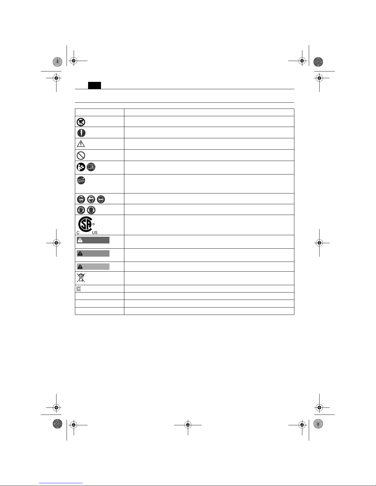
Symbols.
Symbol, character Explanation
Do not touch the rotating parts of the power tool.
Observe the instructions in the text or graphic opposite!
Observe the notes in the text aside!
General prohibition sign. This action is prohibited.
Make sure to read the enclosed documents such as the Instruction Manual and the General Safety Instructions.
Before commencing this working step, pull the power plug out of thesocket. Otherwise there will be danger of injury if the power tool
should start unintentionally.
Use eye protection during operation.
Use ear protection during operation.
This symbol confirms the certification of this product for the USA and
Canada.
This sign warns of a directly imminent, dangerous situation. A false reaction can cause a severe or fatal injury.
This sign indicates a possible dangerous situation that could cause severe
or fatal injury.
This sign warns of a possible dangerous situation that could cause injury.
Worn out power tools and other electrotechnical and electrical prod-
ucts should be sorted separately for environmentally-friendly recycling.
Product with double or reinforced insulation
~ or a. c. Alternating current
1 ~ Alternating current, single-phase
** may contain numbers and letters
DANGER
WARNING
CAUTION
OBJ_BUCH-0000000221-001.book Page 8 Tuesday, July 21, 2015 8:42 AM
9
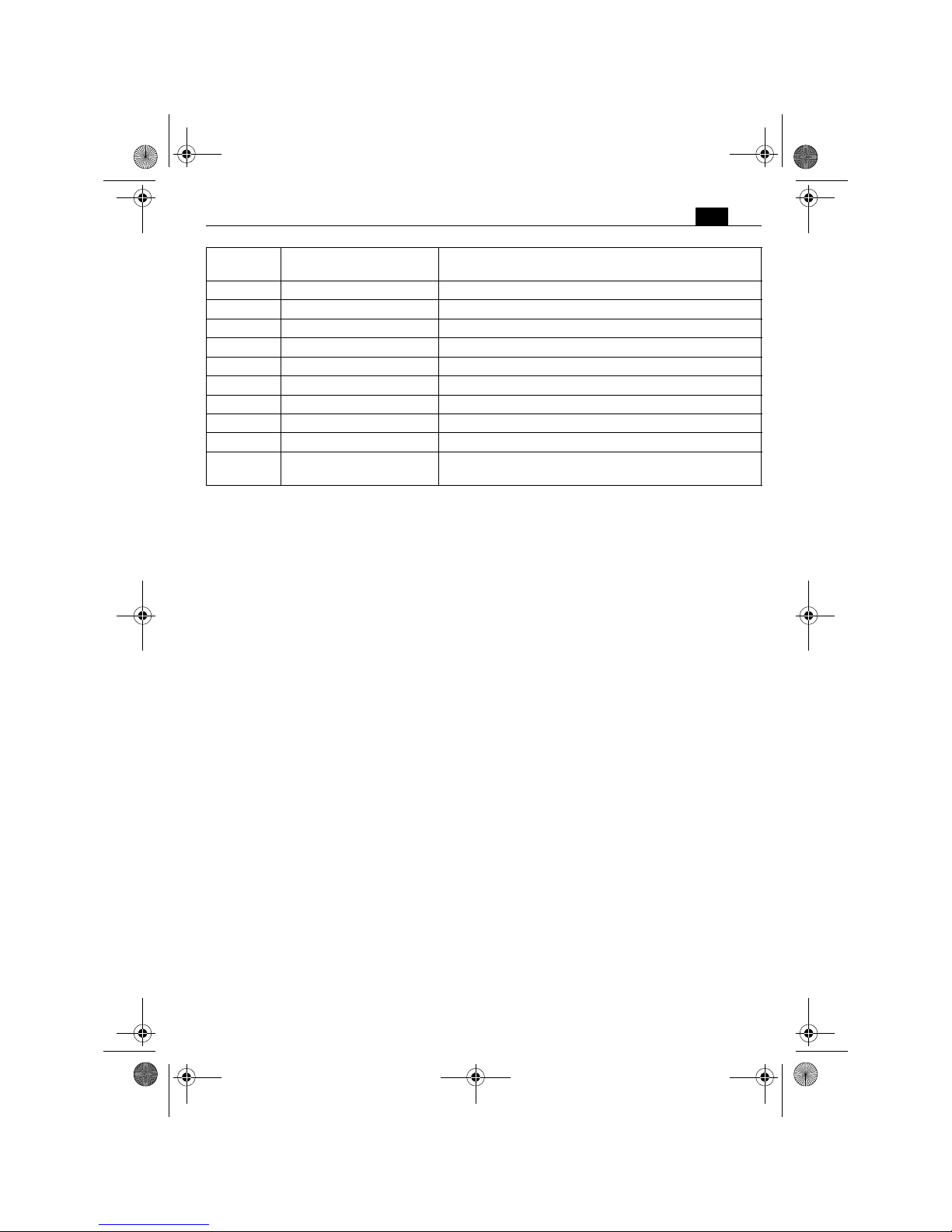
en
Character Unit of measurement,
national
Explanation
n
/min, min-1, rpm, r/min Rated speed
P
W Electrical power
°Angle width
U V Electric voltage
f Hz Frequency
I
A Electric current intensity
m
kg, lbs Mass
l ft, in Length, width, height, depth, diameter or thread
Ø ft, in Diameter of a round part
m, s, kg, A, mm, V, W,
Hz, N, °C, dB, min, m/s
2
Basic and derived units of measurement from the
international system of units SI.
OBJ_BUCH-0000000221-001.book Page 9 Tuesday, July 21, 2015 8:42 AM
10
en
Technical description and specifications.
Before mounting or replacing cutting tool or accessories, pull the power plug.
This preventive safety measure rules out the danger of injuries through accidental starting of the power tool.
All accessories described or shown in this instruction manual will not be included with yourpower tool.
WARNING
OBJ_BUCH-0000000221-001.book Page 10 Tuesday, July 21, 2015 8:42 AM

11
en
Type BOP6 (**) BOP10 (**) BOP10-2 (**) BOP13-2 (**)
Order number 7 205 ... 7 205 ... 7 205 ... 7 205 ...
Current consump-
tion
4.4 A 4.4 A 4.4 A 4.8 A
No-load speed
– 1. Gear
– 2. Gear
0 – 4000/min–0–1500/min
–
0 – 700/min
0–2250/min
0 – 680/min
0–2200/min
On-load speed
– 1. Gear
– 2. Gear
0 – 2700/min
–
0 – 900/min
–
0 – 460/min
0–1350/min
0 – 440/min
0–1300/min
Drilling capacity in
steel
– 1. Gear
– 2. Gear
6 mm, 1/4 in–10 mm, 3/8 in–10 mm, 3/8 in
8 mm, 5/16 in
13 mm, 1/2 in
10 mm, 3/8 in
Drilling capacity in
aluminum
– 1. Gear
– 2. Gear
10 mm, 3/8 in–15 mm, 19/32 in–16 mm, 5/8 in
10 mm, 3/8 in
16 mm, 5/8 in
10 mm, 3/8 in
Drilling capacity in
wood
– 1. Gear
– 2. Gear
15 mm, 19/32 in
–
25 mm, 1 in–30 mm, 1 3/16 in
20 mm, 3/4 in
32 mm, 1 1/4 in
22 mm, 7/8 in
Tap size – M6, 1/4 in M10, 3/8 in M10, 3/8 in
Clamping range of
drill chuck
0.5–10mm
1/64–3/8 in
1.5 – 13 mm
1/16 – 1/2 in
1.5–13mm
1/16 – 1/2 in
1.5 – 13 mm
1/16 – 1/2 in
Thread size of drilling shaft 1/2" – 20UNF 1/2" – 20UNF 1/2" –20UNF 1/2" – 20UNF
Collar diameter 43 mm
15/8in
43 mm
15/8in
43 mm
15/8in
43 mm
15/8in
Weight according to
EPTA-Procedure 01
3.7 lbs (1.7 kg) 4 lbs (1.8 kg) 4.4 lbs (2.0 kg) 4.4 lbs (2.0 kg)
Class of protection /II /II /II /II
OBJ_BUCH-0000000221-001.book Page 11 Tuesday, July 21, 2015 8:42 AM
12
en
Assembly instructions.
Before mounting or replacing cutting tool or accessories, pull the power plug.
This preventive safety measure rules out the danger of injuries through accidental starting of the power tool.
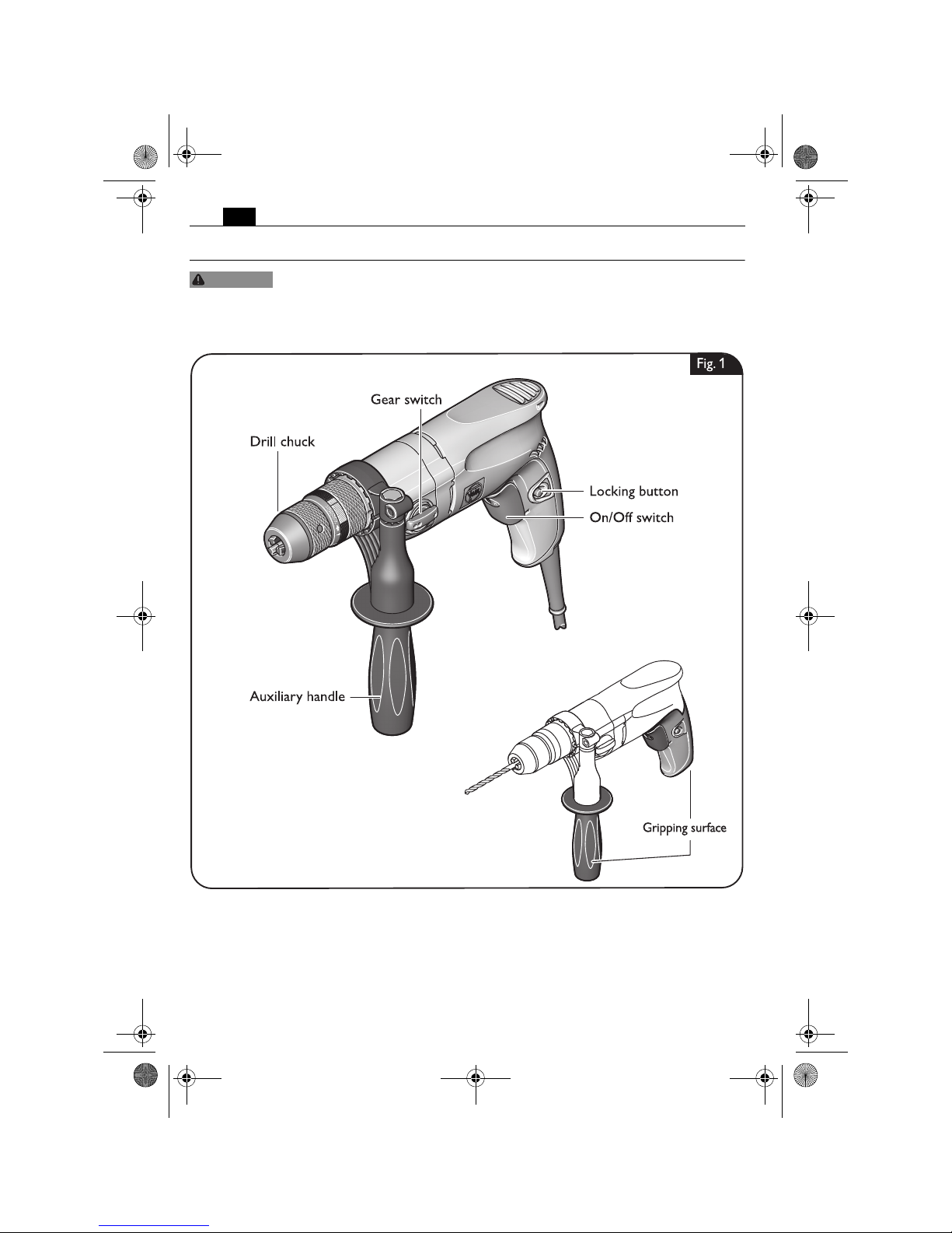
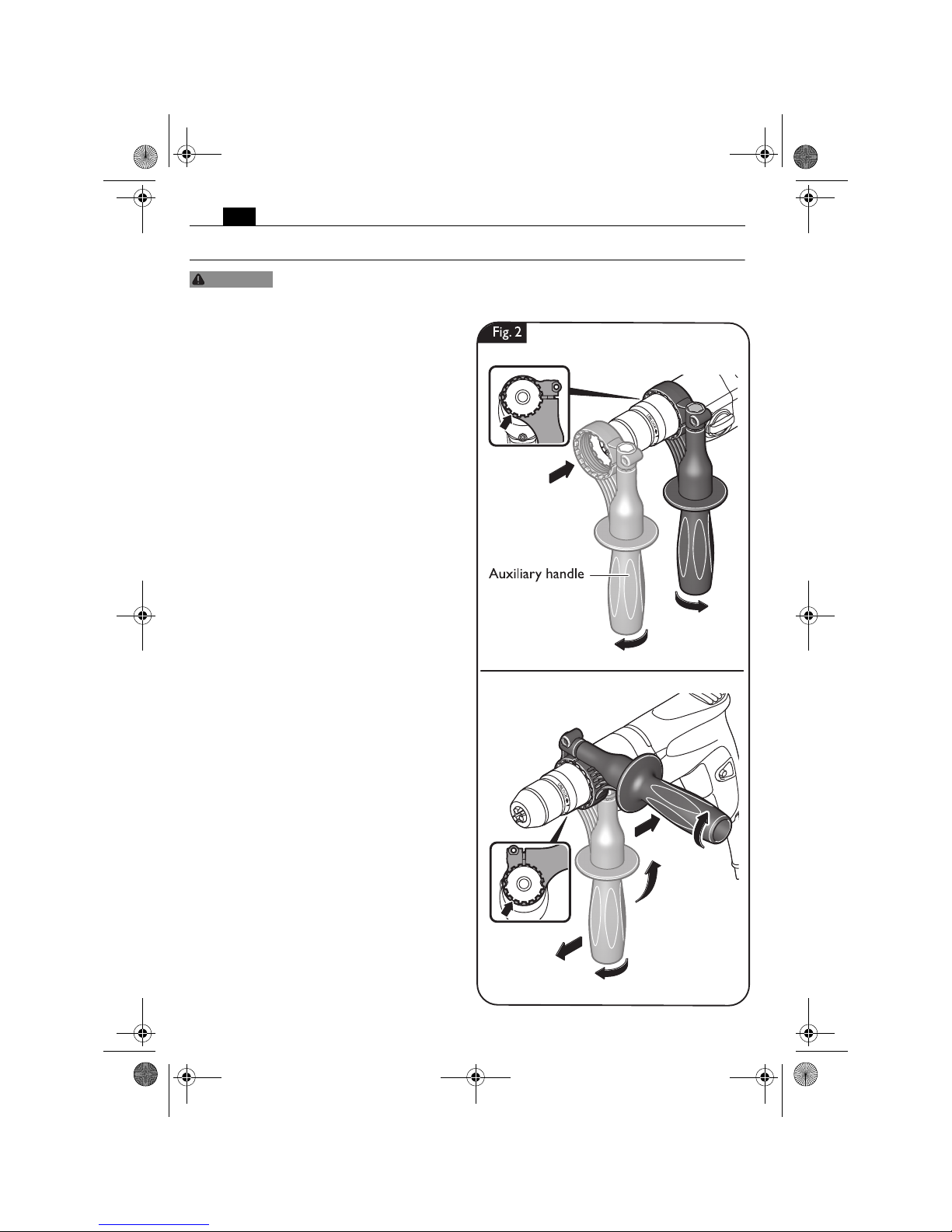
Mounting the auxiliary handle
(figure 2).
To loosen the clamping strap of the auxiliary
handle, turn the handle counterclockwise.
Slide the strap of the auxiliary handle in the
desired working position onto the collar until
the teeth engage into the recesses, and then
tighten.
WARNING
1.
2.
3.
1.
4.
3.
2.
5.
OBJ_BUCH-0000000221-001.book Page 12 Tuesday, July 21, 2015 8:42 AM
13
en
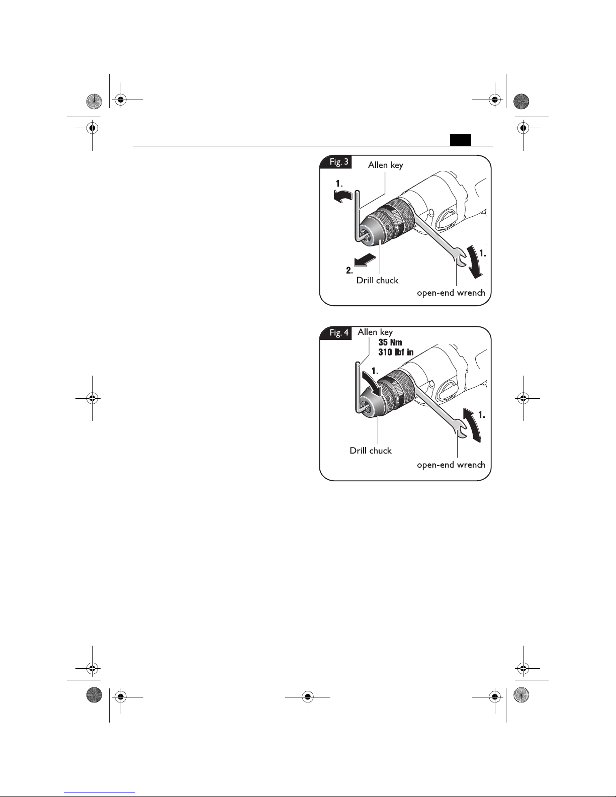
Removing the drill chuck (figure 3).
Insert a hex key into the drill chuck and
tighten the drill chuck.
Unscrew the drill chuck using the hex key and
the open-end wrench (size 17 mm).
Mounting the drill chuck (figure 4).
Mount the drill chuck in reverse order.
Tighten the drill chuck using a hex key and
the open-end wrench (size 17 mm) (tightening torque: 310 lbf in, 35 Nm).
OBJ_BUCH-0000000221-001.book Page 13 Tuesday, July 21, 2015 8:42 AM
14
en
Changing the tool.
Before mounting or replacing cutting tool or accessories, pull the power plug.
This preventive safety measure rules out the danger of injuries through accidental starting of the power tool.
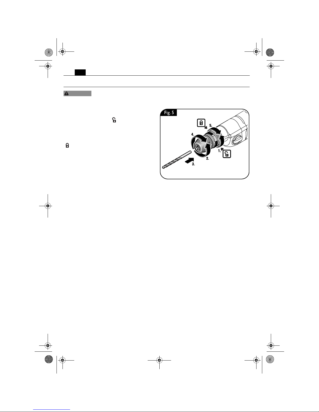
Mounting application tools (figure 5).
To loosen the lock of the drill chuck, turn the
rear sleeve toward the “ ” direction.
Unscrew the front sleeve to replace the application tool.
Tighten the front sleeve and lock the drill
chuck by turning the rear sleeve toward the
“ ” direction.
WARNING
OBJ_BUCH-0000000221-001.book Page 14 Tuesday, July 21, 2015 8:42 AM
15
en
Working instructions.
Before mounting or replacing cutting tool or accessories, pull the power plug.
This preventive safety measure rules out the danger of injuries through accidental starting of the power tool.
For each job, use only the FEIN application tool released and intended for the
respective application.
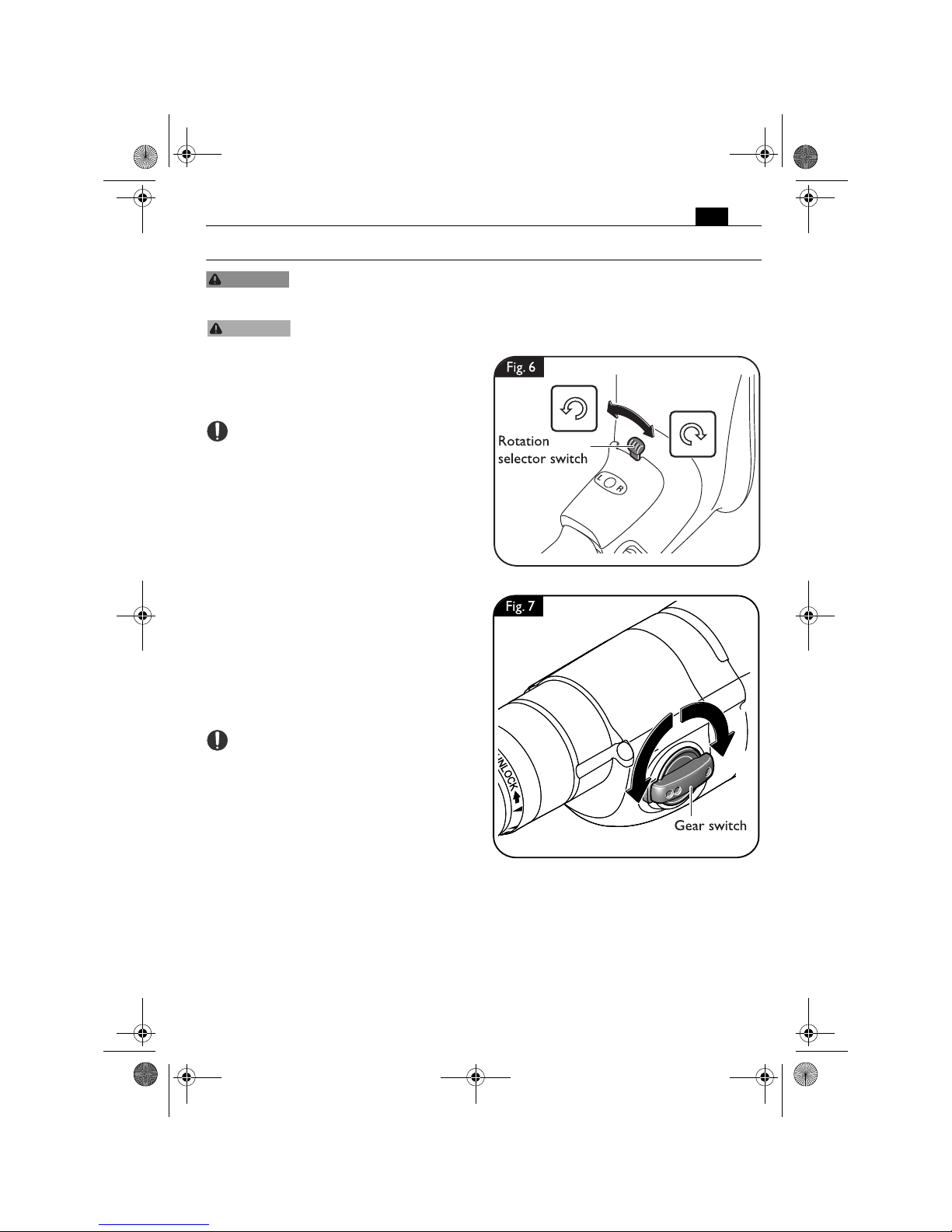
Selecting the rotation direction
(figure 6).
Set the rotation selector switch to right or left
rotation as required.
Adjust the rotation selector switch only
when the machine is at a complete stop.
Adjusting the gear setting (figure 7).
Adjust gear setting 1 to work with low speed
and high torque. This gear setting is suitable
for drilling with large drill bit diameters.
Adjust gear setting 2 to work with high speed
and a lower torque. This setting is suitable for
drilling with small drill bit diameters.
The material-dependent gear setting can be
determined by practical testing.
Adjust the rotation direction only when
the machine is at a complete stop.
WARNING
CAUTION
OBJ_BUCH-0000000221-001.book Page 15 Tuesday, July 21, 2015 8:42 AM
16
en
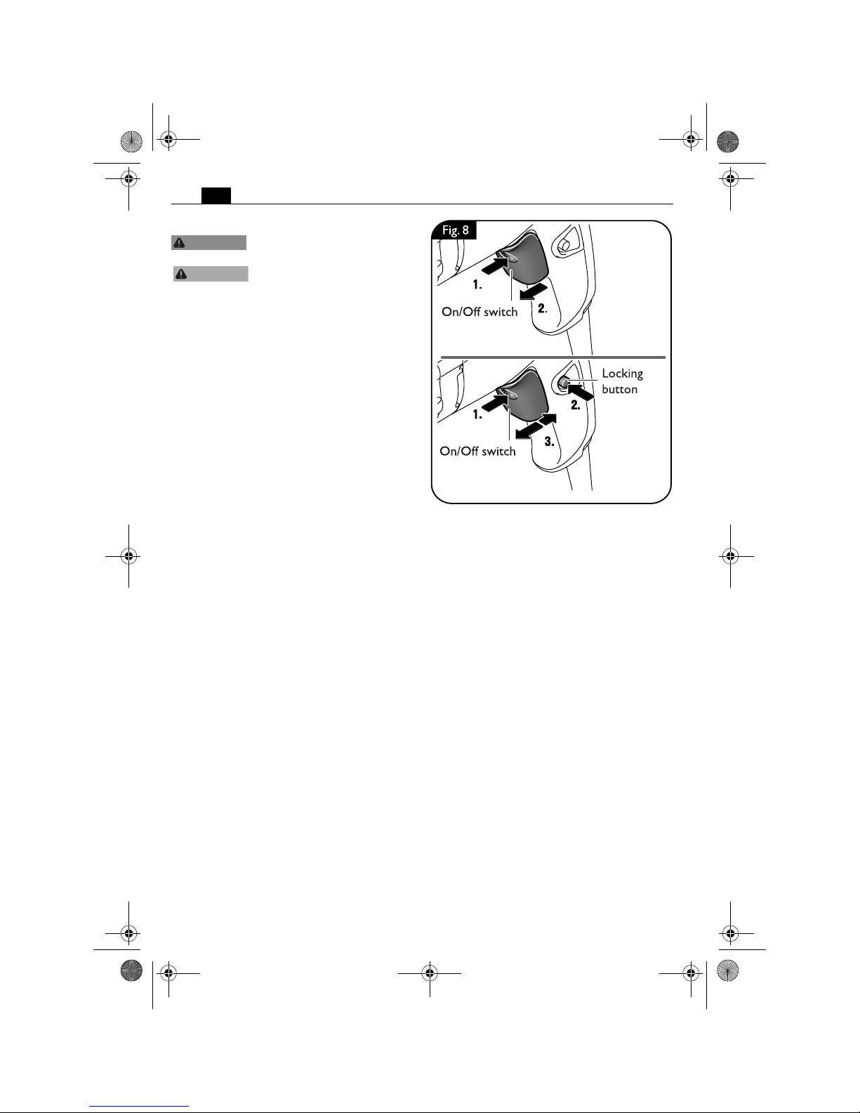
Switching on and off (figure 8).
Check the power supply cable
and the plug for damage.
Always hold the power tool
firmly. Otherwise, you could
lose control over the power tool.
For stationary use in a drill stand, remove the
switched off power tool from the drill stand
at operating temperature every 50 operating
hours and turn it by 180° to achieve uniform
lubrication.
Switching on:
Press the On/Off switch. The speed increases
the more you press the On/Off switch.
Switching off:
To switch off the power tool, release the
On/Off switch.
Locking on:
Press the On/Off switch to the stop and press
in the Locking button.
Release the On/Off switch.
For switching off, briefly press the On/Off
switch until the Locking button disengages.
Release the On/Off switch.
WARNING
CAUTION
OBJ_BUCH-0000000221-001.book Page 16 Tuesday, July 21, 2015 8:42 AM
 Loading...