

Fein ASg 636, ASg 736 Operating Instructions Manual
ASg
636
To
be
handed
to
the
workshop!
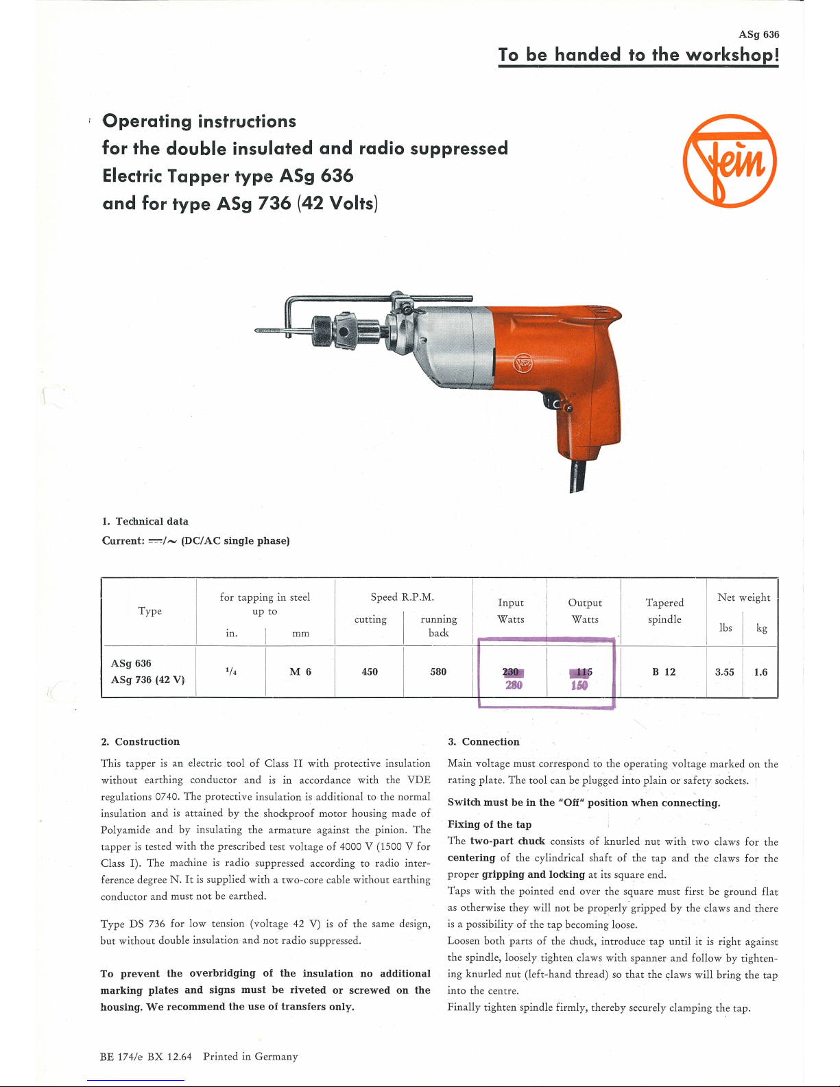
Operating
instructions
for
the
double
insulated
and
radio
suppressed
Electric
Tapper
type
ASg
636
and
for
type
ASg
736
(42 Volts)
1. Te
chnical
data
Current: ==1-
(DC/AC
single
phase)
for ta
pping in
steel Spe
ed
R.P
.M.
I
Input
O
utput
Tap
ered
Net weight
I
Type
I
up
to
c
uttin
g
I
runnin
g I
Watts
I
Watts s
pindl
e
I
I
I
I
lbs kg
I I
back
I
I
m. mm
I
I
A
Sg
636
1
/4
M6
450 580
ASg 736 (42
V)
I
2.
Construction
Th
is
tappe
r is an elec
tric tool of
Class
II
with protective
insula
tion
witho
ut
eart
hing conductor and is
in
accordance with the
VDE
re
gulations 074 0. T he
protecti
ve insula
tion
is
additional
to
the normal
in
sulation a
nd
is attained by
the
shockpr
oof
motor
hou
sing made of
Pol
yamide a
nd
by insula
ting th
e ar
mature
against the pinion. The
ta
pp
er is tested wi
th the prescribed test volt
age of 4000 V (1500 V
for
Class I). The machine is radio supp ressed accor
din
g to r
adio
inter-
feren
ce
degree N .
It
is supplied with a
two
-core cable
without
eart
hing
co
ndu
ctor a
nd must not be
eart
hed.
Type
DS 736 for l
ow
tension (v
olta
ge 42
V)
is of
the
same design,
but without
double insula
tion and
not
rad
io su
ppr
essed.
To
prevent
the
overbridging
of the
insulation
no
additional
marking
plates
and
signs must
be
rivet
ed
or
screwed
on
the
housing.
We
recommend
the
use
of
transfers
only.
BE 174/e
BX
12.64 P
rint
ed
in Ger
man
y
I
I
I
I
B 12 3.55
1.6
I
280
uo
I
I
3.
Connection
Ma
in
voltage must corresp
ond
to
the op
erating voltage mark
ed
on
the
rating plat
e.
The tool can be
plugged
in"
to pla
in
or
safety sockets.
Switch
must
be
in
the
"Off"
position
when
connecting.
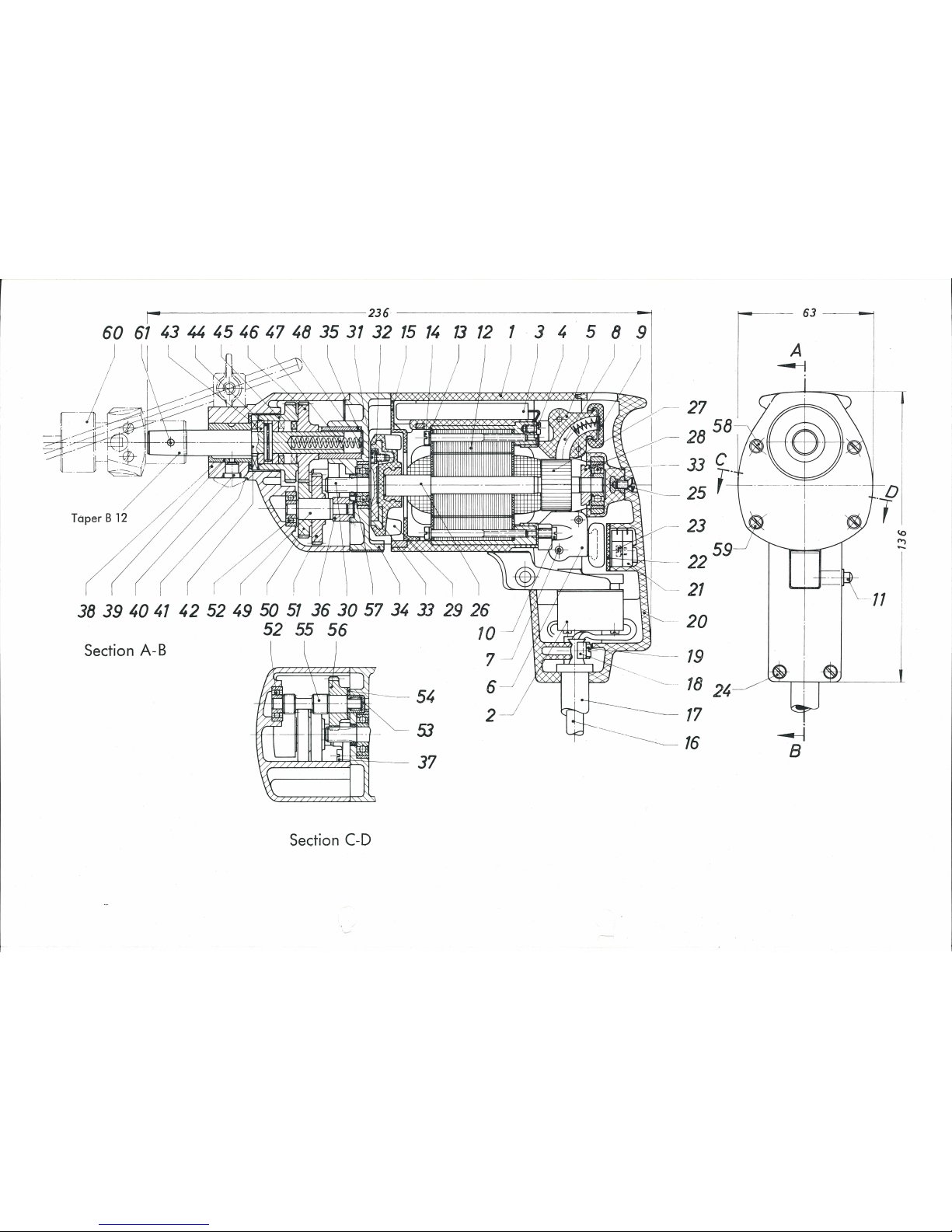
Fixing
of the
tap
Th
e t w
o-part
chuck
consists
of
knurled
nut
with
two
claws for the
centering
of
the cyli
ndrical
shaft
of the t
ap
and
the claws
for
the
p
roper gripping
and
locking
at its square end.
Taps with
the poin
ted
end over the square
must
first
be
gro
und
flat
as
oth
erwise th
ey
will
not
be properly-g
ripped
by the
claws and there
is a
possibili
ty
of the
tap
becoming loose.
Loosen both ·parts of the chuck, i
ntroduce
tap until it is rig
ht
against
the spindl
e,
loosely tighten claws wi
th
spann
er
and
follow
by
tigh
ten
-
ing
knurled nut (left
-hand thread) so that the claws w
ill bring the
tap
in
to
the
centre.
Finall
y tighten s
pindl
e firml y, thereby securely clamping the tap.
-
--
236
_____,
60
61
43
'"
45
46 47 48 35
31
32
15
11,
13
12
1 3 4
8 9
I
Taper B 12
~
23
- i 59
7
-=f=L.=.,~
-- 22
-
21
~
--
::
----
-
38
39
1,0
41
42
52
1,9
50
51
36 30 57
34
33
29 26
52
55
56
10
Section A-B
-).
..
~~~----~
-
54
-~
----
18
24
17
16
2
---
~
53
>' ' ' ' '
.l
'\
,',
"q'
~
37
Section C-D
r-
_;3
1
. I
Lv
ll
~
B
I
---
11
~
f")
-
 Loading...