How it Works
Log In / Sign Up
Buy Points
How it Works
FAQ
Contact Us
Questions and Suggestions
Users
Fein
Loading...
#
71293461000
71293462000
2
71293561000
71293562000
2
71300361000
2
71320461000
2
71400164000
2
71700262000
71901261000
71901361000
72025160000
2
72054760000
72054960000
2
72055260000
72055261000
72055360000
72055361000
2
72055460000
72055461000
72055560000
72055561000
72093860000
2
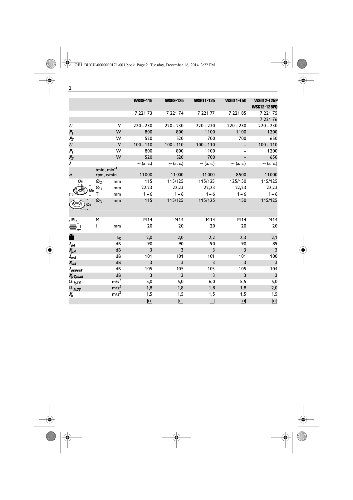
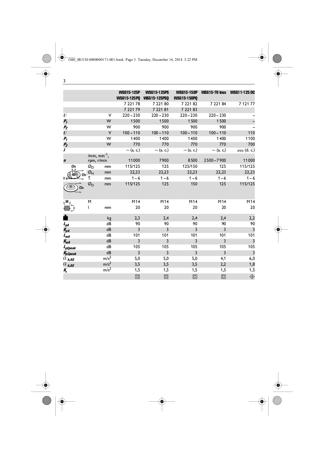
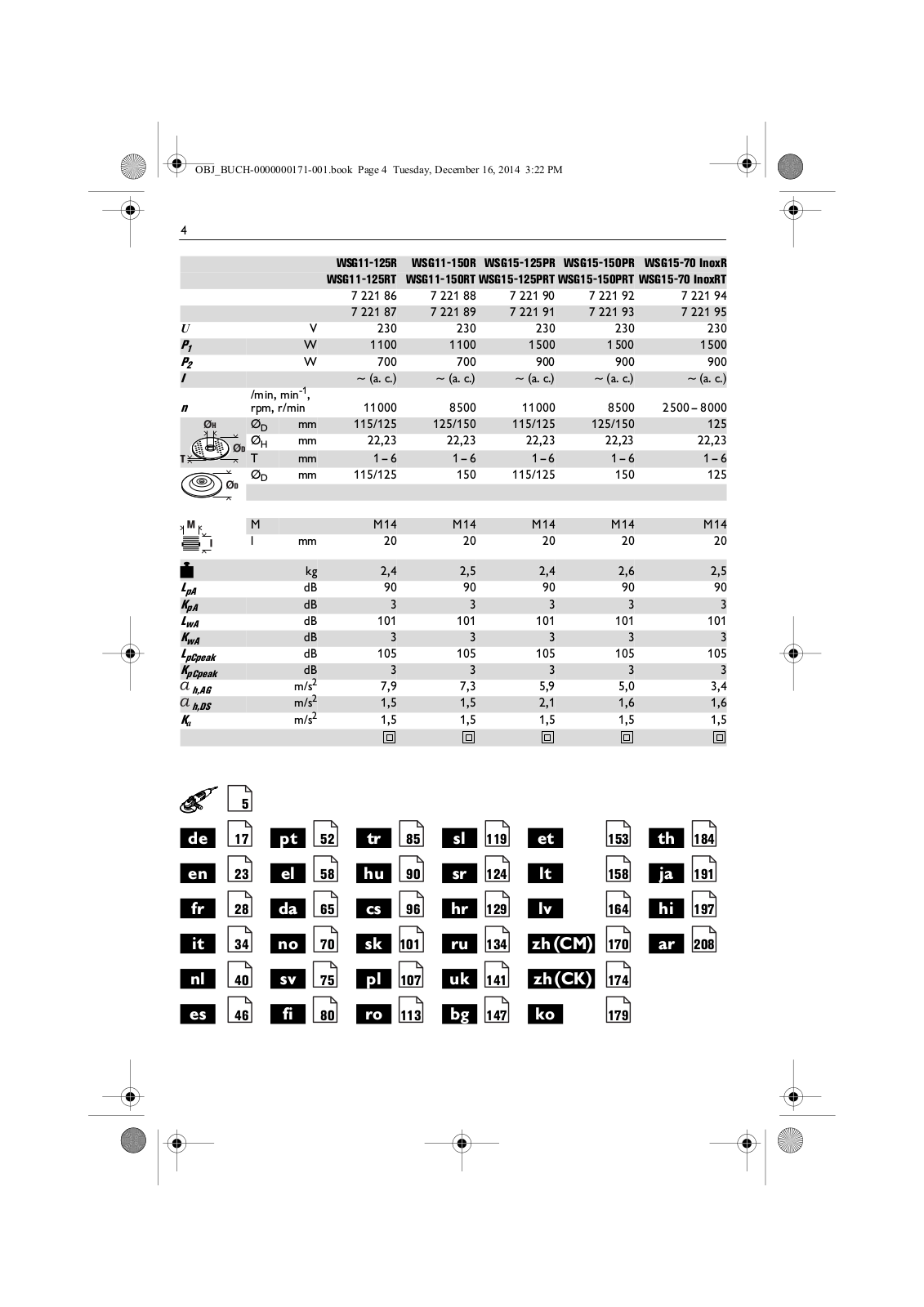
72207800225
72210500237
72210600230
72210700236
72210800232
72211000233
72211100232
72211350014
72211351013
72212600230
72212700230
2
72213100230
2
72214800230
2
72214850010
2
72214851010
72214860000
72214900230
72214950010
72214951010
72216300230
72216351010
72216550010
72216660000
72216760000
72217360000
72217560000
72218760000
72219060000
72219160000
2
72219860000
72220760000
72220860000
72220960000
72221060000
72221160000
72221260000
72221360000
72221361000
72221860000
2
72221960000
72222060000
72222160000
72222260000
72222360000
72226560000
72231660000
72231760000
72231860000
72231960000
72232060000
2
72232160000
72232260000
72232360000
72232460000
72232560000
72294661000
72294662000
72294664000
72294665000
72294667000
72294861000
2
72294862000
72294863000
72294961000
72295263000
72295266000
72295268000
72295276000
72295361000
2
72295461000
72296761000
2
72296762000
72296861000
2
72296862000
72296961000
2
72297061000
72297062000
72297063000
Loading...
Loading...
Nothing found
72219160000
operation manual
208 pgs
11.16 Mb
0
User Manual [de]
2 pgs
510.94 Kb
0
Table of contents
Loading...
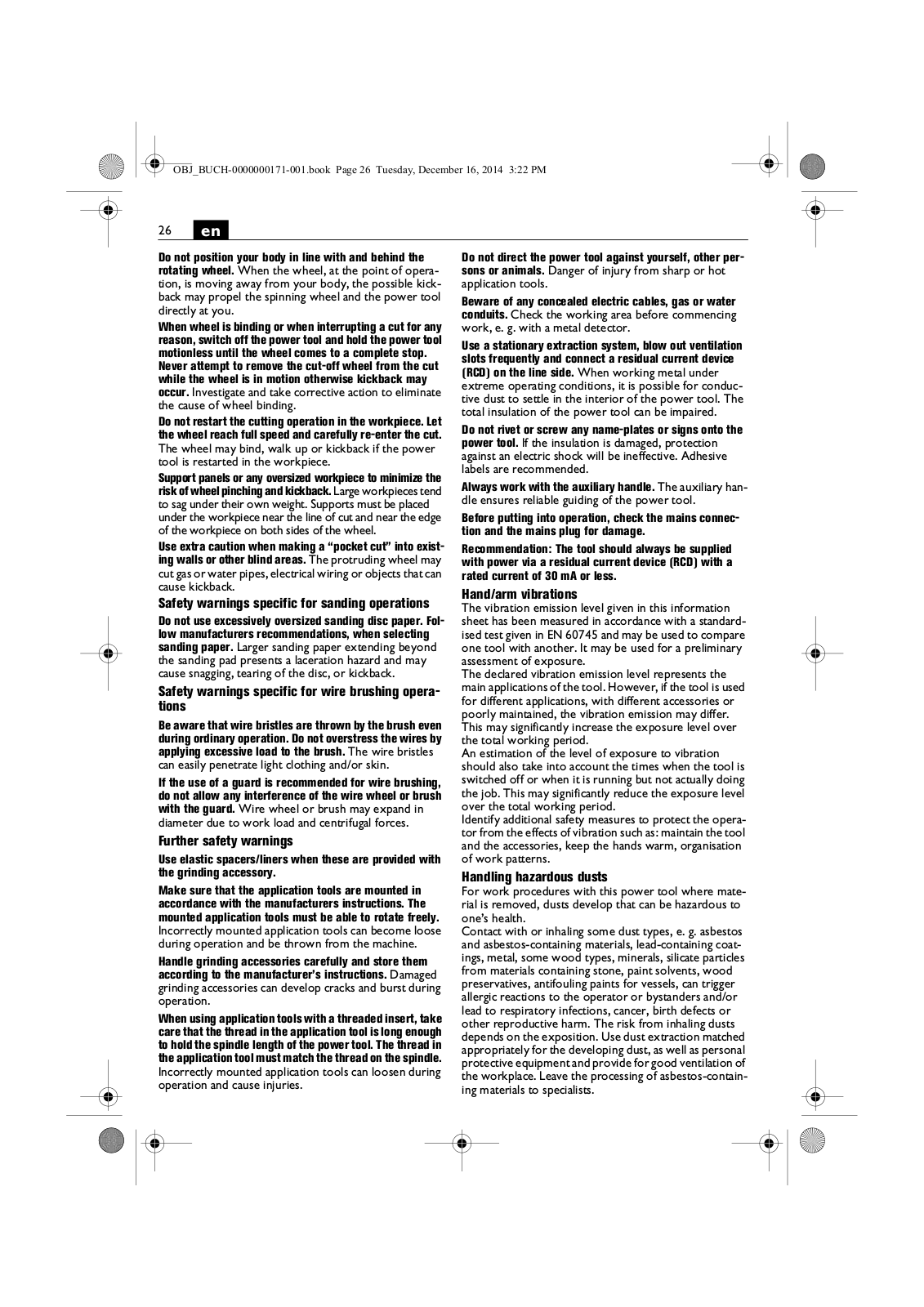
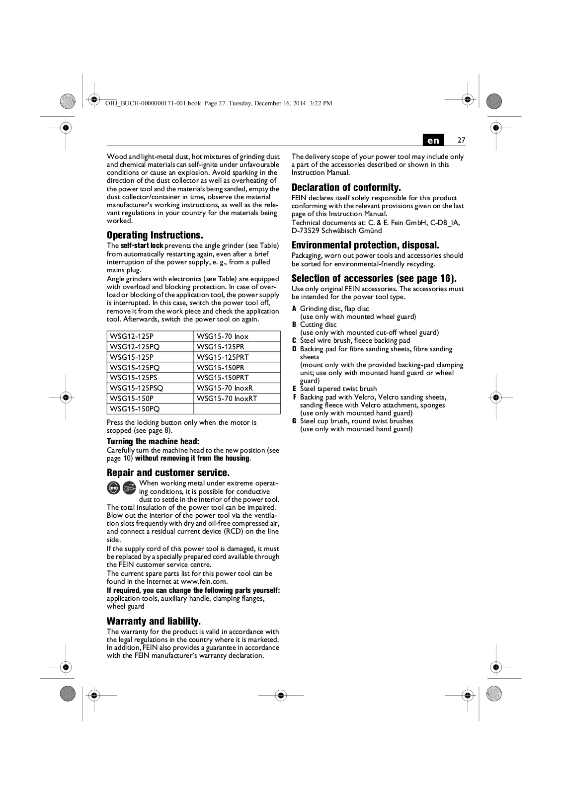
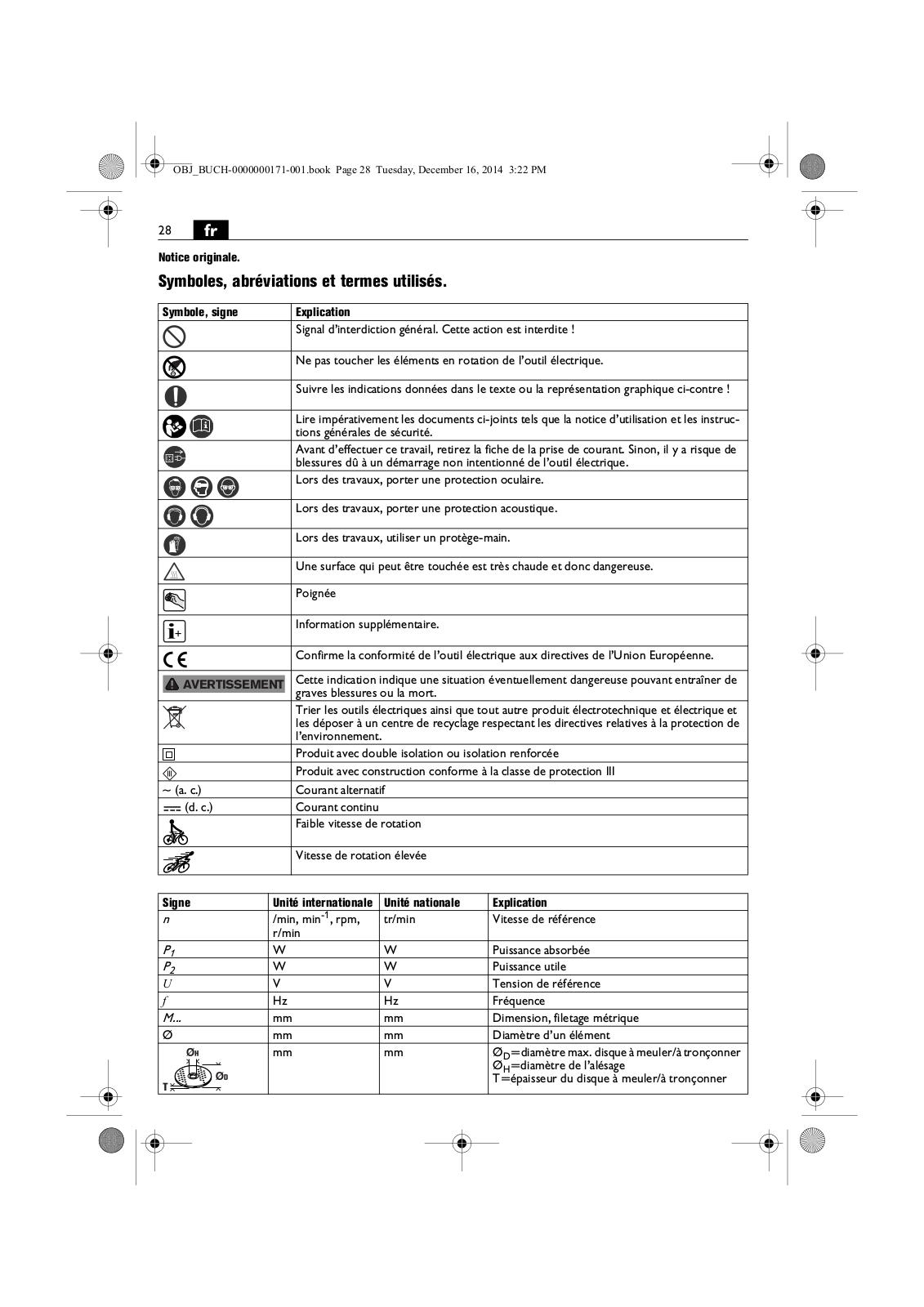
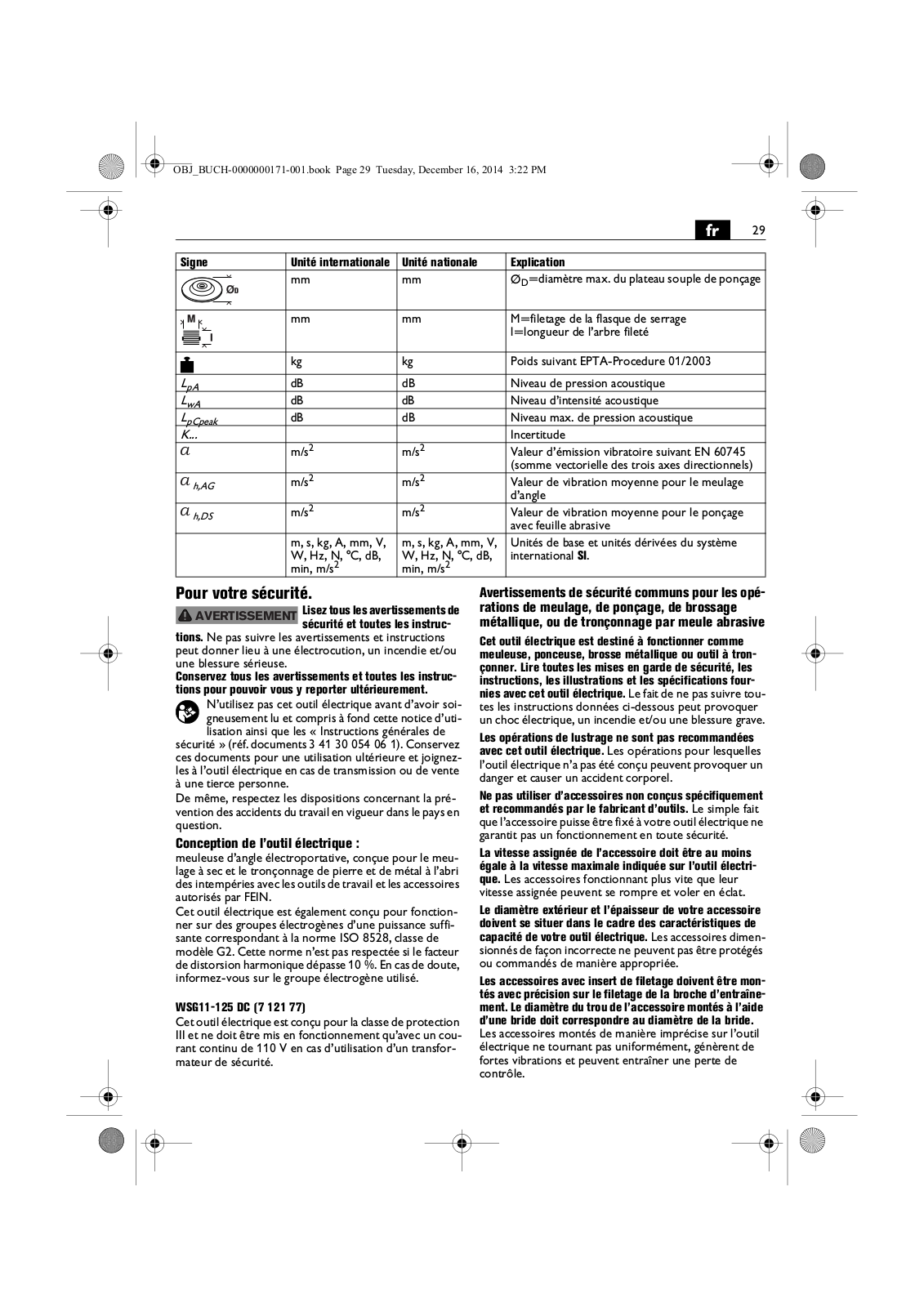
Fein 72219160000 operation manual
...
Fein operation manual
Download
Specifications and Main Features
Frequently Asked Questions
User Manual
Download
Loading...
+
178
hidden pages
Unhide
You need points to download manuals.
1 point = 1 manual.
You can buy points or you can get point for every manual you upload.
Buy points
Upload your manuals
 Loading...