

Page 1
VEK S4 Manual
2009-03-31
S4_Handbuch_GB_090331.doc
Traffic Detector - VEK S4
Page 2

Manual VEK S4
2 03/09 FEIG ELECTRONIC GmbH
Note
© Copyright 2009 by FEIG ELECTRONIC GmbH
Lange Straße 4
D - 35781 Weilburg
http://
www.feig.de
The specifications contained in this document may be changed without prior notice.
This edition replaces all earlier editions of the document.
The information in this guide has been compiled to the best of our knowledge and in good faith. FEIG
ELECTRONIC assumes no liability for the accuracy of the specifications in this guide. In particular FEIG
ELECTRONIC cannot be held liable for consequential damages resulting from improper installation.
Since errors can never be completely precluded in spite of all our efforts, we are always grateful for
corrections and suggestions.
The installation recommendations contained in this guide assume the most favorable circumstances. FEIG
ELECTRONIC assumes no liability for perfect function of the traffic detector in a foreign system environment.
Photocopying and reproduction of this guide in whole or in part as well as translation into other languages is
not permitted without prior written permission from FEIG ELECTRONIC. Also prohibited is storage of this
guide in whole or in part on modern storage devices for the purposes of further processing in data
processing systems.
Please read the user’s guide and safety advisories carefully and in full before starting up the traffic
detector!
Page 3

Manual VEK S4
FEIG ELECTRONIC GmbH 03/09 3
Contents
1 Functional Description ............................................................................................................................ 4
1.1 Vehicle detection................................................................................................................................. 5
1.2 Compensation..................................................................................................................................... 5
1.3 Classification of vehicles..................................................................................................................... 5
1.4 Possible outputs.................................................................................................................................. 6
1.5 Multiplexing methods .......................................................................................................................... 6
1.6 Synchronisation................................................................................................................................... 6
2 Settings ..................................................................................................................................................... 8
2.1 Frequency selection............................................................................................................................ 8
2.2 Multiplexing sequence......................................................................................................................... 8
2.3 Classification....................................................................................................................................... 8
2.4 Output modes.................................................................................................................................... 10
2.5 Time response of the output signals................................................................................................. 10
2.6 RS485 interface ................................................................................................................................ 11
2.7 CANopen interface............................................................................................................................ 11
3 Starting up............................................................................................................................................... 12
4 Display and Operation...........................................................................................................................14
4.1 Display elements............................................................................................................................... 14
4.2 (M)ode button.................................................................................................................................... 14
4.3 Factory settings................................................................................................................................. 15
4.4 Synchronisation display .................................................................................................................... 16
4.5 DIP switches ..................................................................................................................................... 16
5 Case......................................................................................................................................................... 18
5.1 Dimensions ....................................................................................................................................... 18
5.2 Opening the case.............................................................................................................................. 19
6 Technical data......................................................................................................................................... 20
7 Connector and pin assignment ............................................................................................................ 21
7.1 Power supply and interface screwless terminals.............................................................................. 21
7.2 Loop connections.............................................................................................................................. 22
7.3 2x5-pole pin connector for ribbon cables.......................................................................................... 22
7.4 Outputs.............................................................................................................................................. 22
7.5 PE connection................................................................................................................................... 22
8 Standard equipment, accessories........................................................................................................ 23
8.1 VEK M4D – connection kit ................................................................................................................ 23
8.2 VEK M4D accessories, 10 screwless terminals................................................................................ 23
8.3 Service software................................................................................................................................ 23
9 Safety instructions and warnings......................................................................................................... 24
10 4-channel functions ............................................................................................................................... 25
10.1 Scanning speed (4Ch) ...................................................................................................................... 25
10.2 Response sensitivity (4Ch)...............................................................................................................25
10.3 Hysteresis drop (4Ch)....................................................................................................................... 26
10.4 Holding time (4Ch)............................................................................................................................27
10.5 Direction recognition (4Ch)...............................................................................................................28
11 Notes........................................................................................................................................................ 36
Page 4

Manual VEK S4
4 03/09 FEIG ELECTRONIC GmbH
1 Functional Description
The VEK S4 traffic detector is a dual system for the inductive detection of vehicles. Information about the
speed, length and class of a vehicle can be provided using the measuring system (two loop principle) and its
evaluation. The data determined in this way are compiled in a report and provided to a higher level system
(host computer) for further evaluation.
Features:
• 4-channel induction loop detector
• two classification modules (for vehicle classification of, e.g. two lanes)
• automatic speed and length measurement
• vehicle classification in 8+1 classes according to TLS guidelines 2002
• vehicle detection and classification in both directions
• recording of the net time gap (time distance between two vehicles)
• loop dimensions according to TLS guidelines
1
• signal output can be adjusted using Open Drain in the case of excessive speed
• automatic adjustment of the system after switching on
• continuous readjustment of frequency drifts for largely eliminating environmental influences
• sensitivity independent from the loop inductance
• frequency band adjustment
• long loop supply lines possible (up to 300 m)
• simple installation using ribbon cable connection
• RS485 interface
• 4 Open Drain outputs
Other features:
• compact plastic case, mounting on DIN rail
• avoidance of reciprocal influencing of the channels using multiplexing methods
• avoidance of reciprocal influencing of several detectors using synchronisation
• LED display of the loop conditions
• insulation between loop and electronics
• gas surge arrester for improved surge resistance
• CANopen Interface
Setting options:
• five fixed frequency bands independent from the loop inductance
• head gap of the loops per classification module
• sensitivity adjustment of the loop pair per classification module
• adjustment of the vehicle length per classification module
• classification modules can be disconnected by deactivating the detector channels
• output can be set as presence signal, direction signal or general fault indicator, signal for excessive
speed, class-selective signal output
• hardware addresses 2 x (0-15) can be set using DIP switch and address offset via RS485 interface
• other setting options (4-channel functions) actuation threshold per channel in 256 stages
• hysteresis drop of 20-80% per channel
• holding time 1-255 minutes and indefinite per channel
• scanning speed
• direction logic
Compatibility
• downwards compatible to the TLS and FEIG protocol of the VEK S3-1
1
The publisher of the TLS (Technical delivery conditions for route stations) is the Federal Highway Research Institute
(BASt), Bergisch Gladbach
Page 5

Manual VEK S4
FEIG ELECTRONIC GmbH 03/09 5
1.1 Vehicle detection
It is established using an LC oscillator whether a metallic vehicle is in the loop area. The output of the
channel is switched depending on the selected output function.
Loop head gap and loop length are freely selectable and adjustable (see 6 Technical data ). The optimum
loop position must be determined with appropriate measuring methods for laying the loops over reinforced
roadbeds. The laying recommendations must be observed. It is recommended to use the widespread loop
geometry according to TLS II.
1.2 Compensation
A calibration is performed each time the detector is powered up or by pressing the button for longer than 1 s.
After a power interruption, automatic calibration is performed only if the supply voltage was absent for at
least 0.5 s. The calibration time is approx. 1 s if during this time no vehicles have passed through the loop.
Longer calibration times are caused by frequency instabilities; their causes must be determined and
remedied.
1.3 Classification of vehicles
The VEK S4 detector has two classification modules for the vehicle recording. These can be parameterised
independently from each other.
1.3.1 Vehicle data
The typical frequency change for vehicles and its time course on two induction loops with known geometric
dimensions are used for deriving the following factors:
• vehicle class
• vehicle speed
• vehicle length
• net time gap between the vehicles
• occupied time of the loops
• travel direction
The vehicles are classified in 8+1 classes according to TLS guidelines 2002:
• car
• car with trailer
• truck
• truck with trailer
• van
• bus
• motorcycle
• articulated vehicle
• non-classifiable vehicles, e.g. lane changers
1.3.2 Traffic Jam Detection
The detector signals a traffic jam if the traffic is flowing too slowly <10km/h. In this state, a dummy vehicle
with (Other, l = 4.0 m, v = 5 km/h) is reported. Every individual vehicle is also recognised and reported for
traffic queues if the gap between the vehicles enables both loops. The jam signal will be reset when both
loops become free.
Note: A correct detection of driving direction is not guaranteed for all traffic jam situations.
1.3.3 Recording in the case of loop fault
Speed and length measurement and classification is not possible in the case of a defective loop. A dummy
vehicle (Other, l = 4.0 m, v = 0 km/h) is reported for every vehicle which crosses the intact loop in the case of
loop malfunction.
Note: A loop fault is not reported if one or both loops have been intentionally deactivated as the classification
module concerned in this case is completely switched off.
Page 6
Manual VEK S4
6 03/09 FEIG ELECTRONIC GmbH
1.3.4 Tailgating
If a vehicle is driving to close to the car in front a dummy vehicle (Other, l = 4.5 m, v= last vehicle) is reported
with the vehicle speed of the car in front.
Note: A correct detection of driving direction is not guaranteed for all tailgating situations.
1.4 Possible outputs
Two Open Drain outputs each are assigned to every classification module. One of the functions listed below
can also be assigned to each output:
- no function (output deactivated)
- presence of a vehicle on the loops
- direction pulse signal
- pulse for vehicle crossing with vehicle class selection
- exceeding speed limit with vehicle class selection
- speed limit compliance with vehicle class selection
The function setting is made via the serial port using PC / Laptop with service program or host computer.
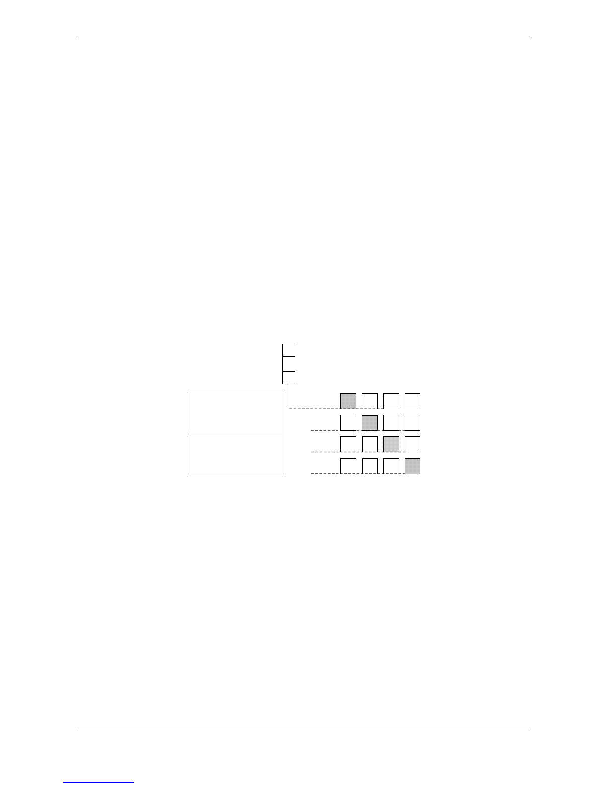
1.5 Multiplexing methods
The connected induction loops are switched on and off in rapid sequence, so that current flows only through
one loop at a time. This prevents mutual interference between the loops of a detector. All loops connected to
a detector can thus operate at the same loop frequency.
Kls-
modul 2
Kls-
modul 1
VEK S4
Time window 1
1 2 3 4
Inductance loops at a detector
1
2
3 4
1 2 3 4
1 2 3 4
Time window 2
T
ime window 3
Time window 4
1.6 Synchronisation
To prevent mutual interference between induction loops of multiple detectors, the latter can be synchronized
with each other using a connection in the front-side ribbon cable. All detectors connected via the
synchronous line process the multiplexing sequence synchronously. Only loops which are active in the same
time window can affect each other. Assigning the loops to the time windows is done by setting the multiplex
sequence.
Note:
• Adjacent loops should be assigned to different time windows.
• Loops in the same time window should be located physically as far away from each other as possible.
Page 7

Manual VEK S4
FEIG ELECTRONIC GmbH 03/09 7
1 2 3 4
1 2 3 4
1 2 3 4
1 2 3 4
1 2 3 4
VEK M4D
Induction loops on
multiple detectors
a) Example without synchronization:
Loop 2 of Detector Nr. 3 can in the
worst case affect all the loops of
Detectors 1,2,4 and themselves be
affected by these loops.
1 2 3 4
1 2 3 4
1 2 3 4
1 2 3 4
1 2 3 4
VEK M4D
Induction loops on
multiple detectors
b) Example with synchronization:
Loop 2 of Detector No. 3 can in the
worst case only affect loops in the same
time window of detectors 1,2,4 or be
affected by these loops.
Page 8

Manual VEK S4
8 03/09 FEIG ELECTRONIC GmbH
2 Settings
The settings described in the following are performed either on the RS485 interface or the CAN interface. It
is recommended that the system be equipped with an operating unit for setting the detectors. The settings
can also be made from a laptop. Setup programs are available from FEIG ELECTRONIC. An appropriate
interface converter is also required.
2.1 Frequency selection
The working frequency is set in order to prevent cross-coupling.
Cross-coupling may occur with adjacent loops or loop lines on other detectors. It is therefore important that
two or more detectors do not operate on the same frequency. A frequency separation of at least 10 kHz
should be maintained for neighboring loops which are not connected to the same detector.
The detector operates in five frequency bands:
Band Frequency range
0 automatic frequency setting (Factory default setting)
1 30 - 40 kHz
2 45 - 55 kHz
3 60 - 75 kHz
4 80 - 100 kHz
5 105 - 140 kHz
It is recommended that all four loops of one detector be set to the same frequency band. Multiplexing
prevents cross-coupling between the 4 loops of a detector.
Note:
For loops whose inductance lies outside the recommended range (see Section 6 Technical data), the
frequency band setting can be restricted. The detector may calibrate to a different frequency than shown in
the above table. This is not a problem as long as there is no cross-coupling with other loops. The currently
set frequencies should therefore be checked.
For long loop supply lines it is recommended to use band 2..4 for frequency setting.
If automatic frequency setting is activated, the VEK S4 uses the device address to choose one of the
frequency range above. Please check the real frequency, because it can differ from the nominal frequency.
For additional notes on preventing cross-coupling Æ see Section 1.6 Synchronisation
2.2 Multiplexing sequence
The default multiplexing sequence is 1-2-3-4. To prevent cross-coupling with neighboring loops of another
detector in exceptional cases, you may change the sequence (e.g. 1-4-2-3). Æ see also Section 1.6
Synchronisation
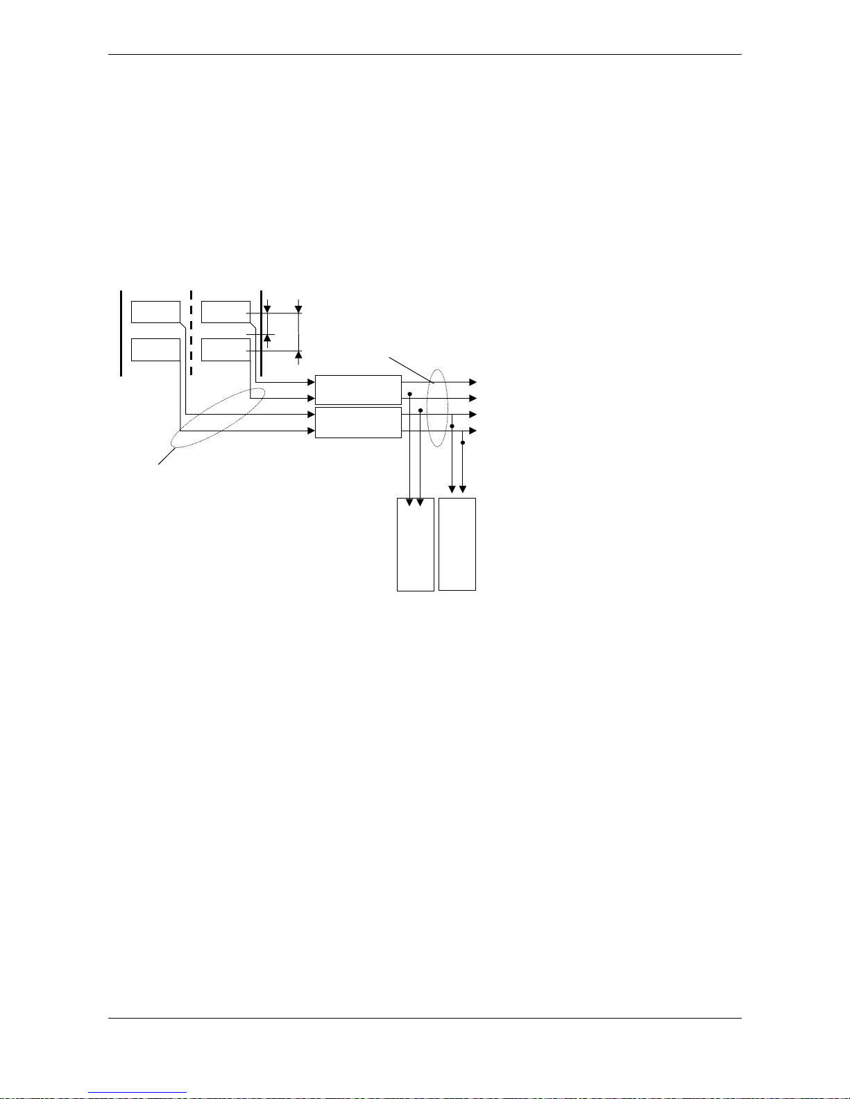
2.3 Classification
Both classification modules of the VEK S4 detector have separate loop parameters so that relevant
parameters per classification module can be set for the vehicle recording. The loop parameters include the
head gap, the amplitude factor for the sensitivity, the constant for the length adjustment and the loop length.
• Head gap
The correct setting of the head gap is relevant for the accuracy of the speed measurement and the vehicle
length.
Page 9
Manual VEK S4
FEIG ELECTRONIC GmbH 03/09 9
• Amplitude factor
The loss of sensitivity due to abnormal loop dimensions, long loop lines or road surface reinforcements is
largely compensated for using the amplitude factor. Automatic evaluation of this factor is also available.
• Length adjustment
The measured vehicle length is corrected with the length adjustment. No vehicle length adjustment is usually
required for normal loops according to TLS with loop lines up to 100 metres.
• Loop length
The loop type of the connected loops is adjusted using the loop length. Currently only the loop types TLS I
and TLS II according to the TLS 2002 guidelines are supported. The loop type TLS II is assumed for a length
up to 125 cm. The loop type TLS I is set for lengths of more than 125 cm.
loop
llenght
Kopfabstand
loop 3
loop 4
loop 1
loop 2
Classifaction-
modul 1
Classifaction-
modul 2
Signals
OpenCollector 3
Counter ever class
and directoin
OpenCollector 4
OpenCollector 1
OpenCollector 2
Loop allocation
is firm
Counter ever class
ans direction
Augangszuordnung
is firm
• Output signals
As already described in 1.4 Possible outputs, each classification module can control two outputs. Refer to
the diagram above for their assignment. One of the five available functions can be set for each output.
Outputs can also be deactivated.
• Vehicle counter
Each classification module has a 16-bit counter per vehicle class and travel direction which can be invoked
via the RS485 interface. It must be noted that the counters roll over at 65535 (2
16
) and restart from 0. It is not
recommended to reset the counters otherwise vehicles can be lost at the time of the reset. The counters in
the detector are not protected against power failure. The detectors must either be buffered with a UPS
system or the counter readings must be regularly read and stored in the higher level system for long-term
counting.
Page 10
Manual VEK S4
10 03/09 FEIG ELECTRONIC GmbH
2.4 Output modes
The following output modes can be set for the four open collector outputs:
Output mode Description
Standard output Normal output mode for presence or direction detection
Group fault message Output indicates loop faults from all loops
always off Output always turned off
always on Output always turned on
Simulation Output switches constantly, e.g. for testing purposes
Inverted or non-inverted signal output can be selected for all output modes.
In the case of standard output the loop faults of the respective channel can be output together with the
logical signal. Which fault is additionally indicated can be set to loop fault (break/short), loop frequency
outside frequency band and calibration procedure.
Factory default setting: Standard output,
Signals not inverted,
Respond to loop fault
The interface can be used to temporarily turn the outputs on or off. This allows you to implement control
tasks such as controlling traffic lights or variable message signs.
In simulation mode the output is constantly repeated according to the following scheme:
- The signal duration corresponds to the set minimum on duration
- The pause time corresponds to the set on delay. If no on-delay is set (0 ms), an idle time of 20s is
assumed.
For the factory set time behavior of the output signals this means a pulse signal of 200 ms duration and an
idle time of 20 s.
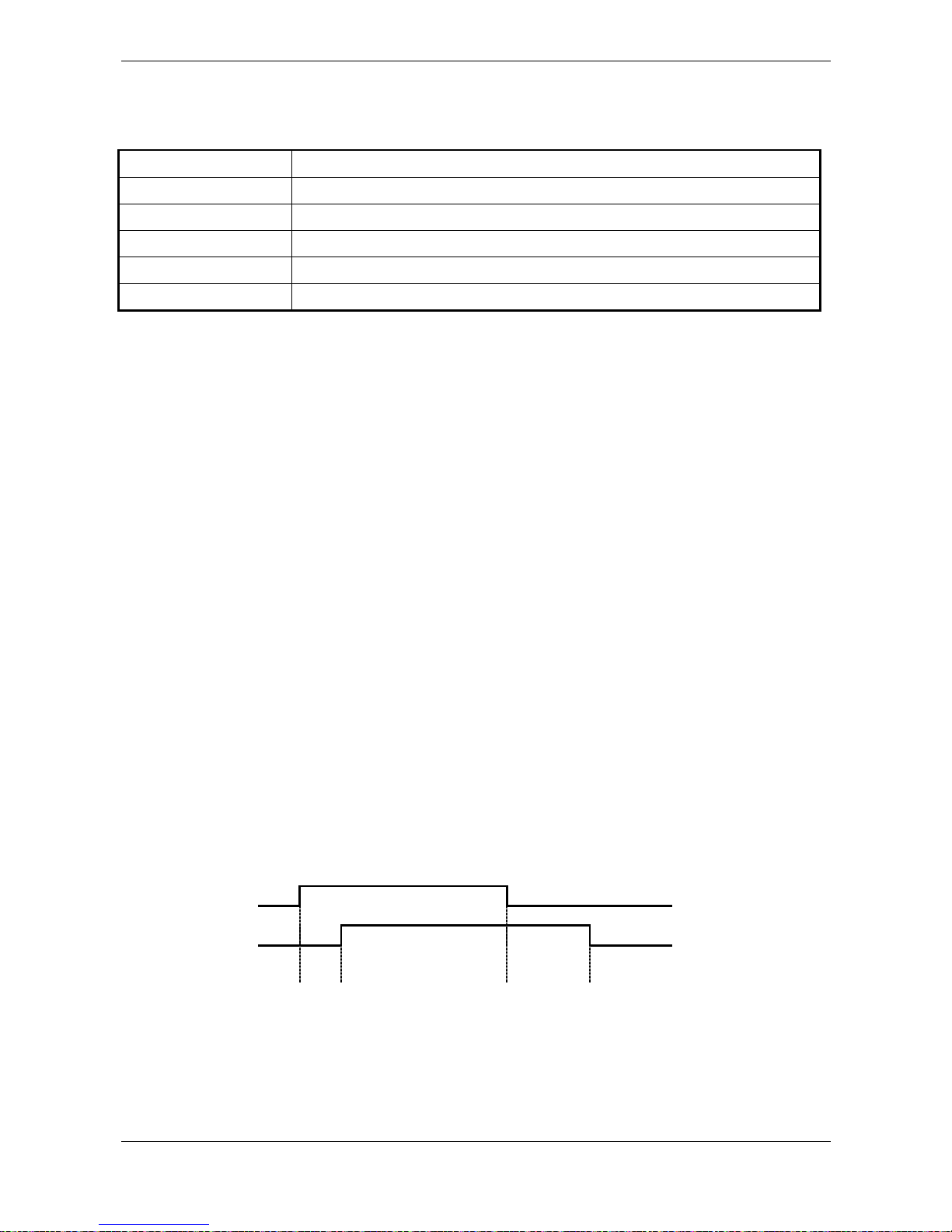
2.5 Time response of the output signals
On-delay, minimum on duration and off-delay for the hardware output signals can be set in 100 ms
increments over a range of 0...25500ms.
Factory default setting: On-delay 0 ms
Off-delay 0 ms
Minimum on duration 200 ms
Loop busy
Output signal
t
on
td ≥ t
dmin
t
off
ton: On delay
t
off
: Off delay
t
dmin
: Minimum on duration
t
d
: Signal duration
Page 11

Manual VEK S4
FEIG ELECTRONIC GmbH 03/09 11
2.6 RS485 interface
Baud rates: 9.6, 19.2, 38.4 kbaud
Parity: no, even, odd parity
Factory default setting: 9.6 kbaud, even parity
Refer to the RS485 documentation for the VEK S4 for the specification of the interface protocols.
The VEK S4 is downwards compatible with the interface protocols defined for the VEK S3. The
protocols based on the TLS defined in the VEK S3 are also supported. In these cases, one VEK S4
behaves like two separately addressable VEK S3 units. Mixed operation of VEK S3 and VEK S4 on
a common bus is not recommended.
Default or factory setting: 100 kBit/s
2.7 CANopen interface
The CANopen standard 301 according to CiA is supported
Baud rates: 100, 125, 250, 500, 800, 1000 kbps
Refer to the CANopen documentation for the VEK S4 for the specification of the CANopen protocols.
Please look for CANopen basics in the specifications from the CiA (CAN in Automation)
organisation.
Default or factory setting: 250 kbps
Page 12

Manual VEK S4
12 03/09 FEIG ELECTRONIC GmbH
3 Starting up
1. Installation – The installation rail must be grounded. Æ 5 Case and 7.5 PE connection
2. Address – The detector address is set to 48 at the factory using the address offset. All detectors which
will be operated on a common interface must be set to different addresses before the commissioning.
Æ
4.5.1 Device address
3. RS485 bus terminator – The RS485 interface must be terminated at the beginning and end in
accordance with the respective specification.
Æ
4.5.2RS485 interface bus termination
4. RS485 baud rate – Select the correct baud rate for the host computer / laptop port. When delivered, the
baud rate for the RS485 interface is set to 9600 bps. If the baud rate of a detector is not known, this can
be reset to 9600 bps by restoring the factory settings.
Attention: All other parameters are also reset when the factory settings are restored.
5. Loop assignment – assign loops to the classification modules. The loops on the connections Loop1 /
Loop2 and Loop3 / Loop4 are assigned to the classification module 1 or the classification module 2
respectively.
6. Loop scanning – Adjacent loop should not operate in the same time window. It must already be
ensured during the planning that neighbouring loops not connected to the same detector are preferably
assigned to different channel numbers. Otherwise the multiplexing sequence must be changed over
during the commissioning.
Æ
1.5 Multiplexing methods
Æ
1.6 Synchronisation
Æ
2.2 Multiplexing sequence
7. Frequency selection – The loops of a detector are usually set to the same frequency band.
Neighbouring loops or loops from neighbouring detectors must be set to different frequency bands.
Æ
2.1 Frequency selection.
8. Head gap – The head gap must be set individually for each classification module. It is usually 400 cm for
TLS I loops and 250 cm for TLS II loops.
9. Amplitude factor – The amplitude factor must be set individually for each classification module. The
displayed out of tune maximum must be checked and corrected using the amplitude factor.
If the S4 protocol is used, the out of tune maximum for TLS I loops for vans should be between 480 and
800 and between 275 and 420 for TLS II loops.
1
Factory settings of the amplitude factor:
Loop TLS type I 60
Loop TLS type II 100
Note: The amplitude factor must be set and checked for every measuring cross section. It is crucial
for the quality of the vehicle classification.
10. Loop length – The loop length of the connected loops must be set for each classification module. The
loop length is usually 250 cm for TLS I loops and 100 cm for TLS II loops.
1
When using the downwards compatible VEK S3 protocol, the maximum for vans should be approx. 20
(+/-5) for TLS I loops and approx. 11 (+/-3) for TLS II loops.
Page 13

Manual VEK S4
FEIG ELECTRONIC GmbH 03/09 13
11. Length adjustment – The displayed and actual lengths of a known vehicle must be compared and
adjusted using the length adjustment. The adjustment of the speed and length measurements should be
made with reference to average values obtained from several measuring cycles.
12. Speed – The speeds of the vehicles must be measured with a sufficiently accurate measuring method
and compared with the detector measured values. The measured speed can be adjusted to the actual
speed using corrections of the head gap for each classification module.
Page 14

Manual VEK S4
14 03/09 FEIG ELECTRONIC GmbH
4 Display and Operation
4.1 Display elements
The front panel of the detector contains 4 green LEDs for indicating the respective loop state.
LED behavior in normal operation:
LED Description
off Loop free
on Loop busy or direction pulse
flashes slowly Frequency calibration running
flashes rapidly Loop fault (break or short)
flashes in pairs automatic evaluation of amplitude factor in process
Chain Synchronization indicator in 8s rhythm
4.2 (M)ode button
The following functions can be activated by pressing the M-key on the front panel.
M-key LED display in
binary code
Function
1x short
Uses LEDs 1-4 to display the hardware address set with DIP
switches 1-4.
1x long
Generates a hardware reset
and before that displays the set hardware address
1x short, 1x long Generates a hardware reset
2x short, 1x long Polls the Master ( ) / Slave ( )
...
6x short, 1x long Resets to factory default settings
The number of short presses of the button is indicated on the LEDs in binary code – left 23, right 2
0
For hardware address ‚0’ the flashing sequence / is output.
The transition between long and short button depression is indicated after 1s by rapid flashing of all LEDs.
After an additional second the LED indicators go out to indicate the function is activated. If the button is
released sooner, during the flashing phase, the function is cancelled!
Page 15

Manual VEK S4
FEIG ELECTRONIC GmbH 03/09 15
4.3 Factory settings
To restore the factory default parameters, proceed as follows:
1) Press button 6x briefly until
shows on the LEDs.
2) Hold button down Æ After one second all LEDs flash rapidly.
After two seconds the LEDs go out.
3) Release button. Æ The essential detector parameters are now set as follows :
Parameter Value Description Comments
Frequency 0 automatic frequency setting depending on device address
Hardware output
Output mode
Inversion
Error output
3
0
0
normal output
not inverting
no loop errors
Standard hardware output for loop
assignment
Loop parameters
Classification module 1
and 2
Head gap 250 cm TLS II loop
Length adjustment 0
Amplitude factor 100 TLS II loop
Loop length 100 cm TLS II loop
Output parameters
Classification module 1
Outputs 1 and 2
Loop assignment
1
2
Output 1: loop 1
Output 2: loop 2
Outputs 1 and 2
Output function
1 Presence
Output parameters
Classification module 2
Outputs 3 and 4
Loop assignment
1
2
Output 3: loop 4
Output 4: loop 4
Outputs 3 and 4 Output function
1 Presence
Address offset 48 Offset
version dependent if necessary !
RS485 port
Baud rate
Parity
Parity detection
4
0
1
9600 Baud
even
active
Refer to the RS485 protocol specification for the basic setting of other parameters !
Page 16

Manual VEK S4
16 03/09 FEIG ELECTRONIC GmbH
4.4 Synchronisation display
Correct function of the synchronization of multiple detectors is indicated by the scrolling effect of the LEDs in
an 8s rhythm. As the device address increases from left to right, the scrolling LEDs also run from left to right
for all synchronized detectors.
Polling of the Master detector is also possible, as described in 4.2 (M)ode button. The Master sends the
synchronization signals over the ribbon cable to the other detectors (Slaves). Selection is random.
4.5 DIP switches
The 8-pole DIP switch is used for selecting the device address and for enabling termination for the CAN bus
and RS485 interface. The DIP switches are located inside the enclosure. As shipped all DIP switches are in
the OFF position.
1
2 3 4 5 6 7 81
ON
Address
0-15
RS485
Pullup / Pulldown
Bus termination
CAN
Bus termination
Note! Before startup check all DIP switches for the correct position! Improper setting can damage
the interfaces.
4.5.1 Device address
The device address results from the hardware device address set using the DIP switches and the software
settable address offset.
DIP switch
1234
Hardware
device address
0000 0
1000 2
0100 4
1100 6
0010 8
1010 10
0110 12
1110 14
0001 16
1001 18
0101 20
1101 22
0011 24
1011 26
0111 28
1111 30
Device address = Hardware device address + Address offset
For downward compatibility to VEK S3 the step size for address offset is 2
Page 17

Manual VEK S4
FEIG ELECTRONIC GmbH 03/09 17
4.5.2 RS485 interface bus termination
+5V
GND
470Ω
470Ω
120Ω 120Ω
. . . . . .
Station
Typical wiring of the RS485 interface
The shown resistors are mounted inside the detector and switch able by the help of the DIP-switches
DIP switch Description
5
470Ω-Pull-up resistor on RS485 B+
6
470Ω-Pull down resistor on RS485 A-
7
Bus termination 120Ω between RS485 B+ and A-
The RS485 bus must be terminated on the front end (control device or repeater) and back end (last detector)
with a 120Ω resistor. Set DIP switch 7 to ON in the last detector.
In addition the two RS485 signal lines B+ and A- must be connected once to 5V resp. to GND with a 470Ω
resistor each. If this has not been done on the control device or repeater, the circuit can be activated on the
last detector using DIP switches 5 and 6.
As shipped the DIP switches are in the ‚OFF‘ position.
4.5.3 CANopen bus termination
CAN High
120
Ω
120
Ω
. . . . . .
CANopen devices
CAN Low
DIP switch Description
8
Bus termination 120Ω between CAN-High and CAN-Low
The CAN bus must be terminated on the front end (control device or repeater) and back end (last detector)
with a 120Ω resistor. Set DIP switch 8 to ON in the last detector.
Page 18

Manual VEK S4
18 03/09 FEIG ELECTRONIC GmbH
5 Case
5.1 Dimensions
Page 19

Manual VEK S4
FEIG ELECTRONIC GmbH 03/09 19
5.2 Opening the case
Opening :
- Loosen upper section A by gently pressing with a screwdriver on the side springs at B.
- Remove upper section.
Closing:
- Check orientation, note contact surface C and PE contact D
- Guide circuit board into rear slot
- Latch upper and lower sections into place
E
C
D
A
B
Page 20

Manual VEK S4
20 03/09 FEIG ELECTRONIC GmbH
6 Technical data
Supply voltage: 12 to 24 V DC +/- 20 %
SELV, limited power sources according to EN 60950-1
Power consumption: typ. 900 mW, max. 1,2 W
Ambient temperature: -20 °C to +70 °C
Storage temperature: -40 °C to +85 °C
Humidity: max. 95% non-condensing
Loop inductance range: 25 – 1200 µH
recommended loop inductance 80 – 300 µH
Working frequency 30 – 140 kHz
Sensitivity
max. loop cable length 300 m
max. loop internal resistance
30 Ω (incl. cable)
Loop inputs galv. isolated (1kV),
90V gas tube arresters to PE contact
Cycle time 8 ms
Loop geometry Head gap: 250 cm and 400 cm
Length: 100 cm and 250 cm
Both loops must have an identical design.
Speed measurement Measuring range 10 km/h to 255 km/h
Tolerance under 100 km/h, +/-3 km/h
Tolerance over 100 km/h, +/-3%
Resolution 1 km/h
Length measurement 10 dm to 250 dm for constant vehicle speed
Tolerance +/- 3 dm
Vehicle classification 8+1 classes Car, car with trailer, truck, truck with trailer, van, bus,
motorcycle, articulated vehicle and unclassifiable vehicle
Outputs Low-Side Switch
Open Drain, short-circuit protected
max. 45 V / 350 mA, R
on
= 1,7 Ω
Enclosure Plastic housing, IP 30 for DIN rail mounting
Polyamide PA 6.6, blue
22.5 x 99 x 114.5 mm (W x H x D, excl. connector)
Integrated function ground contact via DIN rail
Weight 125 g (260 g with packaging)
Connections
Loops 1-4,
altern. CAN-/RS485- Bus and
supply voltage
Open Drain outputs 1-4 (Option)
4-pole plug terminals, 0.2 – 2.5 mm² (AWG 24-14)
Phoenix Combicon MSTBT 2.5, blue
Supply voltage, RS485,
Synchronisation
10-pole IDC plug with flat cable on frontside
Interface
RS 485 2400, 4800, 9600 Baud, 19200, 38400, 57600 Baud, 8E1
Termination 120 Ω, Pull-up / Pull down 470 Ω switchable
CAN 100, 125, 250 kBit/s, 500, 800 kBit/s, 1 MBit/s,
Termination 120 Ω switchable
Page 21

Manual VEK S4
FEIG ELECTRONIC GmbH 03/09 21
7 Connector and pin assignment
Loop 1
OC1 OC2 OC3 OC4
GND 24V
Low
High
1 234
M
B
us
Interface
VEK M4D
Loop 3 Loop 4
Loop 2
Interface
Bus connection
via ribbon cable
Plug terminal
Loops 1 and 2
Plug terminal
GND, 12..24V, Interface Low / High
Plug terminal
Loops 3 and 4
Plug terminal
Outputs 1 to 4
7.1 Power supply and interface screwless terminals
GND 24V
HighLow
Interface
The plug terminal contacts are also connected to contacts of the front-side ribbon cable terminal. This means
the supply and interface connections can also be made either using the plug terminal or ribbon cable. When
multiple detectors are involved, it is practical to combine the plug terminal and ribbon cable, i.e., connection
is made via the plug terminal of one detector, and the additional detectors are connected using ribbon cable
(see also section 8).
Two jumpers are used to connect the RS485 or CAN bus to the plug terminal. The jumpers are located
inside the enclosure. Both jumpers may be inserted only together for CAN or for RS485 !
Interface Low / High verbinden mit
CAN RS485-Bus
Page 22

Manual VEK S4
22 03/09 FEIG ELECTRONIC GmbH
7.2 Loop connections
Loop 1 Loop 2
Loop 3 Loop 4
7.3 2x5-pole pin connector for ribbon cables
Front view
RS485 A- 10
zz
9 RS485 B+
CAN Low 8
zz
7CAN High
Synchronization 6
zz
5GND
GND 4
zz
3GND
24 V 2
zz
1 24 V
The ribbon cable connection is used to synchronize the detectors with each other and to provide the supply
voltage and interface connection. The supply and interface connection to the control device can be made
either using the ribbon cable or a plug terminal (see 7.1 Power supply and interface screwless terminals).
7.4 Outputs
OC1 OC2 OC3 OC4
The Open-Collector outputs are short-circuit protected. When a signal is output the outputs switch on (Low
active).
Vbb U45V
Last
OC1...4
7.5 PE connection
Overvoltages on the loop inputs are diverted to PE using the integrated gas tube arrester. For this there is a
function ground contact on the enclosure bottom (see also 5.2 Opening the case– Part D), which connects
the inserted circuit board with the DIN rail. When the circuit board is inserted, be sure that contact surface C
fits in the PE contact spring D of the enclosure! The DIN rail must be connected to PE in the system with low
impedance !
Noise immunity of the VEK S4 cannot be guaranteed without a PE connection to the DIN rail !
Page 23

Manual VEK S4
FEIG ELECTRONIC GmbH 03/09 23
8 Standard equipment, accessories
The single unit includes four 4-pole plug terminals. This allows you to make all the connections including
the serial interface.
For larger systems the connection between the detectors is generally made using a ribbon cable. Therefore
the 10-pack includes only the terminals for the loop connections. Additional connection parts must be
ordered depending on which connection option is selected.
What you need:
• For connecting multiple detectors together a 10-pole ribbon cable with a corresponding number of spring
action contacts
• For the supply voltage and communications interface either a plug terminal or a longer ribbon cable per
system
• If using the open collector outputs an additional plug terminal per detector
The following accessory sets are available:
8.1 VEK M4D – connection kit
Contents: 4 plug terminals, configured 1m ribbon cable with 16 spring action contacts and an additional
spring action contact
The ribbon cable is trimmed to length by the user for the number of detectors. If the power is provided
through the plug terminals this set allows you to equip e.g. 4 systems with 4 detectors each. Using the
additional spring action contact you can alternatively provide power directly through the ribbon cable.
Additional plug terminals are required if using the detector outputs!
8.2 VEK M4D accessories, 10 screwless terminals
For additional connections or as a spare part for the loop connections
8.3 Service software
The traffic detector can be parameterised using the S4Com service program. As the VEK S4 is downwards
compatible and supports the interface protocols of the VEK S3, the S3ComWin service program can also be
used. Please pay attention here to the special features of the addressing. Æ 4.5.1 Device address
Note:
In order to avoid bus conflicts, the host computer must be disconnected from the RS485 bus while the
service program is being used.
Page 24

Manual VEK S4
24 03/09 FEIG ELECTRONIC GmbH
9 Safety instructions and warnings
• The device may be used only for the purpose intended by the manufacturer.
• This manual must be kept in an accessible place and handed out to each user.
• Improper modifications and use of replacement parts and add-on equipment not purchased or
recommended by the manufacturer may cause fire, electrical shock and injury. Such measures will
therefore result in liability exclusion and the manufacturer will assume no warranty.
• The warranty terms of the manufacturer in place at the time of purchase are considered valid. No liability
is assumed for improper, incorrect manual or automatic setting of parameters for a device or for improper
use of a device.
• Repairs are to be performed by the manufacturer only.
• The power supply must be fulfill the requirements for SELV and limited power sources according to
EN 60950-1.
• Wiring, startup, maintenance, measurement and setting work on the traffic detector are to be performed
only by trained electrical specialists with relevant accident protection instruction.
• All work on the device and its installation must be performed in accordance with the national electrical
regulations and local code.
• The user is responsible for installing and connecting the device according to the recognized technical
regulations in the country of installation as well as other regional accepted codes. Of particular
importance are cable dimensioning, safeguarding, grounding, shut-down, isolation, isolation monitoring
and overcurrent protection.
• The unit is not approved for use as a safety component in accordance with Machine Directive 98/37/EC,
Construction Products Directive 89/106/EEC or other safety regulations. Additional safety devices are
required in systems having the potential for hazard.
Page 25

Manual VEK S4
FEIG ELECTRONIC GmbH 03/09 25
10 4-channel functions
The VEK S4 detector can also be used for presence detection with flexible direction recognition due to its
integrated 4-channel functions (4Ch). The parameters for use as a presence detector are explained in this
chapter.
Please note that changing the following parameters can influence the classification results or deactivate
classification modules.
10.1 Scanning speed (4Ch)
The response time of the detector is dependent on the number of active loop channels and the adjustable
interference filter. The scanning speed is doubled respectively by changing the multiplexer to two loop or
single loop operation. The scanning speed can be further increased by deactivating the interference filter
whereby the response time can be reduced from to normal 16 ms to 2 ms.
Attention: The interference resistance of the system is also reduced for fast response times.
Activating the interference filter adversely affects the classification behaviour of the
classification modules.
Scanning mode Interf. filter Response time
4 loops on 16 ms
2 loops on 8 ms
1 loops on 4 ms
4 loops off 8 ms (Default or factory setting)
2 loops off 4 ms
1 loop off 2 ms
It is also possible to deactivate individual loops without changing the reaction time. It must be noted that the
time window of the deactivated loop is assigned to another active loop. Distances between loops must also
be complied with here to avoid couplings which operate in the same time window.
Attention: When a loop is deactivated, the classification module concerned is also deactivated.
10.2 Response sensitivity (4Ch)
The sensitivity for every channel in the range from 0.02% - 10.63% ∆f/f can be selected in 256 steps. In
order to minimise interference, the sensitivity should be set as high as is necessary, i.e. the response
sensitivity should be set as high as possible.
The sensitivity setting is usually adjusted in large steps and the response threshold values are nor selected
higher than 120. Settings above 120 and fine adjustments are used for applications where vehicle
differentiations are required. For example, buses can be selectively detected with a large loop with the
dimensions 10.0 m x 2.5 m.
Page 26

Manual VEK S4
26 03/09 FEIG ELECTRONIC GmbH
Parameter
value
Response
threshold
value
Sensitivity (∆ f/f)
0 4 0.02 % maximum sensitivity
1 10 0.04 %
2 20 0.08 %
3 30 0.13 %
4 40 0.17 %
5 50 0.20 %
::
11 110 0.46 %
12 120 0.5 % (Factory setting)
13 130 0.54 %
::
41 410 1.71 %
42 420 1.75 %
43 430 1.79 %
::
100 1000 4.17%
::
255 2550 10.63 % lowest sensitivity
Note: The response thresholds of the VEK S4 are different from the response threshold of the VEK M4D for
the same sensitivity (∆ f/f).
10.3 Hysteresis drop (4Ch)
In order to avoid an intermediate loss of the occupied signal for vehicles with a high undercarriage such as
articulated buses, trams, trucks with trailers etc, it is possible to modify the switching hystereses. An
interruption-free detection of critical vehicles is then also possible with low closure resistance setting. The
drop value threshold factory setting is 75%.
Page 27

Manual VEK S4
FEIG ELECTRONIC GmbH 03/09 27
Output signal for
25% drop value threshold
Drop value
threshold at 25%
Drop value threshold at 75%
Cut-in threshold
Output signal for 75% drop value
threshold
Detuning by vehicle
Output signal
10.4 Holding time (4Ch)
Separate holding times between 1 and 255 minutes can be set for each channel on the detector. A zero
setting means infinite waiting time. If the loop of a detector channel is occupied longer than the set holding
time, the detector channel tunes again.
Factory setting: 20 minutes
Page 28

Manual VEK S4
28 03/09 FEIG ELECTRONIC GmbH
Logic module 1
Logic module 2
Parallel counting
Signals
Direction A
4+2 Count er
Direction logic
Direction B
Direction A
Direction B
4 Counter
allocation
Loop allocation
adjustable
10.5 Direction recognition (4Ch)
In addition to the simple direction recognition present in the classification modules, the VEK S4 detector has
two parameterisable logic modules for the direction-dependent recording of vehicles. Complex evaluation
algorithms using double loops are integrated in the detector. The direction logic generates logical output
signals which can be output via a hardware output or via an interface depending on the setting. The logic
signals are also counted in parallel in the detector independently.
Two direction logic modules each with 2 inputs (double loops) and 2 outputs (directions A and B) are
integrated in the detector. The assignment of the loops to the logical inputs and the assignment of the logical
outputs to the Open Drain outputs can be adjusted.
The assignment meters can be invoked via the interface. For counting in time intervals, the counting result
must be determined from the meter readings at the start and at the end of the time interval. It must be noted
that the counters roll over at 65535 (2
16
) and restart from 0. It is not recommended to reset the counters
otherwise vehicles can be lost at the time of the reset. The counters in the detector are not protected against
power failure. The detectors must either be buffered with a UPS system or the counter readings must be
regularly read and stored in the higher level system for long-term counting.
In addition to the double loop counting, a four loop counting which counts parallel passages is integrated. If
needed, the total count can be corrected by the assumed lane-changers in the superordinate system using
these count values.
Depending on the application, several different evaluation logics can be set for each of the four logical
outputs. The different logics for the direction recognition are shown briefly below. The detailed method of
working for different traffic situations follows afterwards.
Page 29

Manual VEK S4
FEIG ELECTRONIC GmbH 03/09 29
Direction logic Signal output Signal waste Remark
D1 - Continuous signal 1 left 1. loop
DB - Continuous signal
both loops
Allocation 1. loop
D2 – Continuous signal 2 Allocation 2. loop
left 2. loop
Signal output in opposite direction takes place only
again if both loops were free before-
F1 – Wrong driver 1
(Factory setting)
F2 – Wrong driver 2
Correct behavior with column traffic and Rangierer.
Different behavior with wrong driver situations (see
appendix).
BS - both loops
Allocation 2. loop
Correct behavior with column traffic should not seem to
Rangierer.
FE – Feig left 1. loop Correct behavior with column traffic and Rangierer
SF – loop freely left 2. loop
Collection of single vehicles and Rangierer. Columns
should not occur
PB – Park bay related to the direction
Expenditure for
impulse with adjusted
minimum signal
period
(Standard 200ms)
For short in and exits (see appendix)
With all logics the loop occupied first determines the counting and/or expenditure direction. I.e. for example
loop 1 is occupied first, takes place expenditure and counting for direction A.
Page 30

Manual VEK S4
30 03/09 FEIG ELECTRONIC GmbH
10.5.1 Direction detection in various traffic situations
Various traffic situations are shown in the following for Loops 1 and 2. The evaluation of the direction signal
is performed in the same manner in the reverse direction of travel as well for Loops 3 and 4 or other loop
combinations.
Explanations for the table:
xx
Direction logic, gray = logic with incorrect count in this traffic situation.
___
Imp Æ Direction pulse Imp Æ Direction pulse in the opposite direction
on Æ Continuous signal on off Æ Continuous signal off
The direction signal is output on the channel of the first loop to be traversed.
10.5.1.1 Single vehicle
PB
D2 D1 DB F1 F2 FE SF BS
Ri1 Ri2
12
1 2
on on
12
on||
|
|
||Imp Imp Imp
1 2
|
||off||
|
Imp Imp
12
off off Imp Imp
Page 31

Manual VEK S4
FEIG ELECTRONIC GmbH 03/09 31
10.5.1.2 Traffic line
PB
D2 D1 DB F1 F2 FE SF BS
Ri1 Ri2
1 2
on on
12
on||
|
|
||Imp Imp Imp
1 2
|
||off||
|
Imp Imp
1 2
|
||on||
|
1 2
off||
|
|
|
|
___
Imp
12
on||
|
|
||Imp Imp Imp
1 2
|
||off||
|
Imp Imp
12
off off Imp Imp
10.5.1.3 Wrong-way driver 1
PB
D2 D1 DB F1 F2 FE SF BS
Ri1 Ri2
1 2
on on
12
on||
|
|
||Imp Imp Imp
1 2
off||
|
|
|
|
12
off off
___
Imp
___
Imp
Page 32

Manual VEK S4
32 03/09 FEIG ELECTRONIC GmbH
10.5.1.4 Wrong-way driver 2
PB
D2 D1 DB F1 F2 FE SF BS
Ri1 Ri2
1 2
on on
12
on||
|
|
||Imp Imp Imp
1 2
|
||off||
|
Imp Imp
12
|
||on||
|
1 2
off||
|
|
|
|
___
Imp
12
off off
___
Imp
10.5.1.5 Maneuverer 1
PB
D2 D1 DB F1 F2 FE SF BS
Ri1 Ri2
1 2
on on
12
on||
|
|
||Imp Imp Imp
1 2
off||
|
|
|
|
12
on||
|
|
|
|
1 2
|
||off||
|
Imp Imp
12
off off
Imp Imp
Page 33

Manual VEK S4
FEIG ELECTRONIC GmbH 03/09 33
10.5.1.6 Maneuverer 2
PB
D2 D1 DB F1 F2 FE SF BS
Ri1 Ri2
1 2
on on
12
on||
|
|
||Imp Imp Imp
1 2
|
||off||
|
Imp Imp
12
|
||on||
|
1 2
off||
|
|
|
|
Imp
12
on||
|
|
||Imp Imp Imp
1 2
|
||off||
|
Imp Imp
12
off off Imp Imp
Page 34

Manual VEK S4
34 03/09 FEIG ELECTRONIC GmbH
10.5.1.7 Wrong-way driver in traffic line
PB
D2 D1 DB F1 F2 FE SF BS
Ri1 Ri2
1 2
on on
12
on||
|
|
||Imp Imp Imp
1 2
|
||off||
|
Imp Imp
1 2
|
||on||
|
1 2
off||
|
|
|
|
___
Imp
12
off off
___
Imp
10.5.1.8 Cross-traffic
PB
D2 D1 DB F1 F2 FE SF BS
Ri1 Ri2
1 2
on on
12
on||
|
|
||Imp Imp Imp
1 2
|
||off||
|
Imp Imp
12
|
||on||
|
1 2
off||
|
|
|
|
___
Imp
12
off off
___
Imp
All logics except for PB in Direction 1 will result in incorrect counts in this traffic situation, since they
count in instead of out.
Page 35

Manual VEK S4
FEIG ELECTRONIC GmbH 03/09 35
10.5.2 Direction logic „Parking Bay“
This direction logic is used for short entrances and exits. This logic suppresses compromising of the count
by cross-traffic on Loop 1. This means it is non-critical whether Loop 1 is placed in the passing lane or in the
maneuvering area.
1 2 Parking
Lane
1 2
Parking
Lane
Parking
The placing of the loops depends on which travel direction backups are anticipated in. In travel direction 1 →
2 no backups are permitted! In travel direction 2 → 1 even vehicles in traffic line situations are correctly
counted, whereby the vehicle gap must always enable a loop.
Logic for travel direction 1 → 2
• The counter pulse arrives when both loops have been fully traversed
• Correct count for individual vehicles
• Correct count for maneuvering as well
• Traffic jam situation and traffic lines may not occur for travel direction 1 -> 2!
Logic for travel direction 2 → 1
• The counter pulse arrives as soon as Loop 2 is left in the direction of Loop 1
• Correct count for cross-traffic as well
• Correct count for traffic lines
• Correct count even for maneuvering of a single vehicle
• No maneuverers are allowed within a traffic line!
Page 36

Manual VEK S4
36 03/09 FEIG ELECTRONIC GmbH
11 Notes
 Loading...