

Page 1

Traffic detector
NE
Manual
1 / VEK MNE2
GBR
VEK M
Page 2

Manual VEK MNE1 / VEK MNE2
Notes
Copyright 2015 by FEIG ELECTRONIC GmbH
Lange Straße 4
D-35781 Weilburg
GBR
Tel.: +49 6471 3109-0
www.feig.de
Version: 2015-09-14 VEK MNE1 / VEK MNE2
This edition renders all previous editions invalid.
The information in this document is subject to change without notice.
Without FEIG ELECTRONIC’s prior written permission, it is not permitted to produce complete or partial copies and reproductions of this manual and translations into other languages. It is also prohibited to store total this manual on modern information carriers for manipulation purpose in data processing systems
The compilation of the information in this document is based on our best knowledge and belief. FEIG
ELECTRONIC GmbH accepts no responsibility for the correctness and completeness of the information in
this manual. FEIG ELECTRONIC GmbH will not be held liable for consequential damages arising as the result of incorrect or incomplete information.
Since it is impossible to avoid mistakes despite our sincerest efforts, we are always grateful if these are
pointed out.
The installation recommendations provided in this document are based on favorable conditions. FEIG
ELECTRONIC does not provide any warranty for the proper operation of the traffic detector in foreign system
environments.
FEIG ELECTRONIC GmbH does not warrant the material described herein to be free of third party industrial
property rights. With this document, FEIG ELECTRONIC GmbH does not issue any licenses to its own or
others patent rights or industrial property rights.
Warranty claims against FEIG ELECTRONIC GmbH can only be made by the purchaser and are not transferable. FEIG ELECTRONIC GmbH’s warranty obligation extends only to products supplied by FEIG
ELECTRONIC GmbH. The warranty excludes any liabilities for the entire system.
The description of the products, their application, capabilities and performance shall not be considered as
warranted properties and are subject to technical change.
Before using the traffic detector, please read the operating and safety instructions with care!
General information about this document
Language of the original instructions: DeutschThe following characters are used in the functional description to point out
the different danger zones and useful hints.
indicates that a potential risk to persons exists, if the procedure is not carried out as described.
indicates that the controller is at risk of being damaged.
indicates information that is important for the operation of the device.
indicates useful information that is relevant but not essential to the utilization of the device.
2 09/2015 FEIG ELECTRONIC GmbH
Page 3

Manual VEK MNE1 / VEK MNE2
TABLE OF CONTENTS
1 Safety Precautions and Warning Notes ................................................................................................. 4
2 Maintenance .............................................................................................................................................. 4
3 Functional Description ............................................................................................................................ 5
3.1 Vehicle Detection System ................................................................................................................... 5
3.2 Adjustment .......................................................................................................................................... 5
3.3 Output Options .................................................................................................................................... 5
3.4 Multiplex-Procedure ............................................................................................................................ 5
4 Enclosure .................................................................................................................................................. 6
5 Technical Specifications ......................................................................................................................... 7
6 Licenses and Directives .......................................................................................................................... 8
7 Installation Instructions ........................................................................................................................... 9
7.1 Installation Location ............................................................................................................................ 9
7.2 Pin Assignment ................................................................................................................................... 9
8 Ordering Code ........................................................................................................................................ 10
9 Accessories ............................................................................................................................................ 10
10 Elements on the Front ........................................................................................................................... 11
10.1 LED Display ....................................................................................................................................... 11
10.2 Push Buttons ..................................................................................................................................... 12
10.3 DIP-switches ..................................................................................................................................... 12
10.4 USB Socket ....................................................................................................................................... 13
GBR
11 Adjustment Options ............................................................................................................................... 14
11.1 Sensitivity, On Threshold .................................................................................................................. 14
11.2 Hysteresis, Off Threshold .................................................................................................................. 15
11.3 Frequency ......................................................................................................................................... 16
11.4 Hold Time .......................................................................................................................................... 16
11.5 Output, Signal Shape ........................................................................................................................ 17
11.6 Invert Output Signal Behavior ........................................................................................................... 17
11.7 Loop Error Behavior (Error Mode) ..................................................................................................... 17
11.8 Loop/Output Assignment ................................................................................................................... 18
11.9 Pulse Timing Edge ............................................................................................................................ 18
11.10 Timing of Output Signals (On Delay, Off Delay, min. Duration) ........................................................ 18
11.11 Direction Detection (Dir. Mode, Direction Mode) .............................................................................. 19
11.12 Direction Logic ................................................................................................................................... 19
12 Notes ........................................................................................................................................................ 26
FEIG ELECTRONIC GmbH 09/2015 3
Page 4

Manual VEK MNE1 / VEK MNE2
1 Safety Precautions and Warning Notes
GBR
• The device must only be used for the purpose intended by the manufacturer.
• Store the operating instructions in an accessible location and pass it on to every user.
• Unauthorized modifications and the use of spare parts and accessories, which are not sold or recom-
mended by the manufacturer of the equipment, can result in fires, electric shock and injury. Therefore,
such measures lead to an exclusion of liability and the manufacturer will not accept liabilities.
• For the device, the manufacturer's warranty provisions in force at the time of purchase are valid. No liability is assumed for improper or wrong manuals or automatic adjustment of parameters of a unit or the improper use of a device.
• Do not open the enclosure.
• Repairs shall only be carried out by the manufacturer.
• The power source used must meet the requirements for SELV circuits and current limited power sources
in accordance with EN 60950-1.
• Connecting, commissioning, maintenance, testing and adjustment work on the traffic detector must be
carried out by qualified electricians with the relevant accident prevention training.
• Observe valid VDE regulations when handling devices that are exposed to electrical voltage. In particular,
but not limited to, these are VDE 0100, VDE 0550/0551, VDE 0700, VDE 0711, VDE 0860, VDE 0105, as
well as the fire and accident prevention regulations BGV A3 (previously VBG 4).
• The fact that an operational indicator turns off is no indication that the unit was disconnected from the
power supply and that it is de-energized.
• All work on the unit and its installation must be carried out in accordance with the national electrical codes
and local regulations.
• It is the responsibility of users or installers to make sure that the equipment is installed and connected in
accordance with recognized engineering practice in the country of installation and relevant local regulations. Particular attention must be focused on cable dimensions, fuses, grounding, shutdown, isolation,
insulation monitoring and overcurrent protection.
• The combined operation of extra low and low voltage on both outputs of the relays is not permitted!
• The round plug corresponds to the basic insulation properties. If the relay contacts carry voltages > 48
VAC/DC as well as for all -R230 versions, the isolation of all connecting cables of the 11-pin round plug
must be designed for 230 V AC.
• The device must not be used as a safety unit in accordance with the Machinery Directive 2006/42 / EC,
the Construction Products Directive 89/106 / EEC or any other safety regulation. In systems with potential
risks, additional safety equipment is required!
2 Maintenance
The unit does not contain parts that need servicing by the installer or user.
Do not open the enclosure.
4 09/2015 FEIG ELECTRONIC GmbH
Page 5

Manual VEK MNE1 / VEK MNE2
3 Functional Description
The traffic detectors VEK MNE1 and VEK MNE2 are systems for the inductive recognition of vehicles that
must be installed in control cabinets.
Properties:
• 1-channel (VEK MNE1) or 2-channel (VEK MNE2) inductive loop detector
• Compact plastic enclosure to be mounted in the control cabinet on sockets on DIN rails
• Automatic adjustment of the system after it is turned on
• Continuous readjustment of frequency drifts to neutralize environmental influences
• Sensitivity independent of loop inductance
• Fixed dwell times regardless of the degree of coverage of loops
• Frequency adjustment
• Direction sensing (only on VEK MNE2)
• Multiplexing method to avoid mutual interference of the loop channels
• LED indication of the loop conditions
• Galvanic isolation between loops and electronics
• Relay outputs
• USB-interface for the diagnosis and other adjustments
Adjustment options:
• Adjustments by means of a 8-pole DIP-switch and a 4-pole DIP-switch (only on VEK MNE2)
• two frequency levels
• Threshold of each channel in 255 steps (via 4 stage DIP-switch)
• Off hysteresis of 20-80% per channel
• Hold time 1-255 minutes and infinite per channel (via DIP-switch 5 minutes and infinite)
• Detector channels can be turned off
• Output adjustable as presence, pulse, direction signal (only on VEK MNE2) or loop failure
GBR
3.1 Vehicle Detection System
An LC oscillator determines whether a metallic vehicle is located in the loop region or not. The output of the
channel is controlled in accordance with the selected output function.
3.2 Adjustment
The adjustment of the loop channels is carried out after turning on the detector or by pressing the front button for about 1 s. After a power failure, an automatic adjustment is carried out only when the operating voltage has been interrupted for a period of at least 0.5 s. The adjustment time is approximately 1 s, if the loop is
not crossed by vehicles during this time.
Extended adjustment periods also result by external influences on the loop frequency, their causes must be
identified and eliminated.
3.3 Output Options
Depending on the selected output function, the outputs provide a presence signal, pulse signal, direction
signal (only on VEK MNE2) or loop error. The adjustment of the pulse signal can also be used to select
whether an output takes place when driving on or leaving the loop.
In addition to the inversion of the output signals, both outputs may be turned on or off individually and permanently.
3.4 Multiplex-Procedure
The connected induction loops on the 2-channel traffic detector VEK MNE2 are turned on and off in rapid
succession. Current always only flows through one loop. Mutual influence of the loops of a detector is thus
prevented. Both loops connected to a detector can operate at the same frequency.
FEIG ELECTRONIC GmbH 09/2015 5
Page 6
Manual
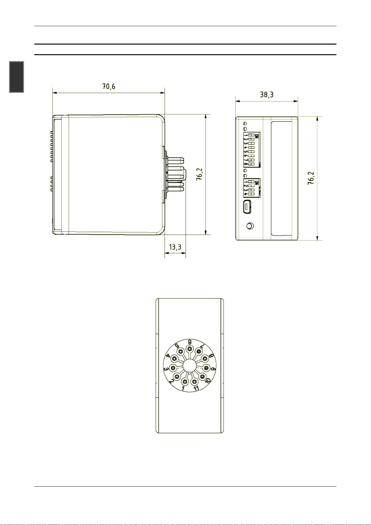
ear view
VEK MNE1 / VEK MNE2
FEIG ELECTRONIC GmbH
Front view (VEK MNE2)
4 Enclosure
GBR
Side view
6
R
: Pins on the 11-pin round plug
09/2015
Page 7

Manual VEK MNE1 / VEK MNE2
5 Technical Specifications
Enclosure:
Plastic enclosure ABS, blue
Round plug, 11-pin PPO, fiberglass-reinforced, black
Supply voltage -R230: 100-240 V AC, 50-60 Hz
-R24: 10-30 V AC/DC
SELV, power source with limited output (EN 60950-1)
Power consumption typ. 500 mW, max. 2 W
Protection class -R230: II
Ambient temperature -37 °C to +70 °C
Storage temperature -40 °C to +85 °C
Relative humidity max. 95 % non-condensing
Loop inductance range: 20-700 uH
Recommended loop inductance: 100-300 uH
Frequency of operation 30-130 kHz
Sensitivity
max. Loop feed cable 200 m
max. internal resistance of loop
Loop inputs 1 kV, galvanic insulation
Cycle-/response time 12 ms
Limiting speed for passenger cars:
with presence detection max. 200 km/h
with direction recognition max. 200 km/h for a 2 m loop head gap
Outputs:
Relays -R230: 2 A; 230 V AC; 60 W / 125 VA
Connections:
Inductive loops, power supply, controlled outputs
0,01 % to 2,55 % (∆f/f) in 255 steps
20 Ω, incl. feed cable
-R24: 2 A; 48 V AC/DC; 60 W / 125 VA
common on 11-pin round plug with base isolation
GBR
USB-interface USB socket Mini-AB, 5-pin
USB-interface virtual serial interface
FEIG ELECTRONIC GmbH 09/2015 7
Page 8

Manual VEK MNE1 / VEK MNE2
6 Licenses and Directives
GBR
8 09/2015 FEIG ELECTRONIC GmbH
Page 9

Manual VEK MNE1 / VEK MNE2
7 Installation Instructions
7.1 Installation Location
Traffic detector VEK MNEx shall be installed into a switchboard or switchboard-like enclosure. The choice of
the installation location must be such that the operation of the traffic detector cannot be impaired by humidity,
dust or dripping water.
7.2 Pin Assignment
The table below shows the different pin assignments of the 11-pin round plug for the different pin-outs –A .. –
G.
Pins on 11-pin round plug
Pin as-
signment
-A
-B
-C
-D
-E
-F
-G *
L / 24V -R230: L
-R24: 10-30 V AC/DC
N / GND -R230: N
-R24: GND
L1a, L1b Inductive loop terminal channel 1
L2a, L2b Inductive loop terminal channel 2
L-Com common terminal Inductive loop channels 1 and 2, special assignment
NO1, NO2 normally open contact Output 1 or output 2
NC1, NC2 normally closed contact Output 1 or output 2
COM1, COM2 common contact Output 1 or output 2
COM1+2 common terminal for a common contact output 1 and 2, special assignment
1 2 3 4 5 6 7 8 9 10 11
NO2 COM2 NC1 COM1 L1a L1b - NO1 NC2
NO2 - COM1 NO1 L1a L1b COM2 NC1 NC2
NC2 COM2 NC1 COM1 L1a L1b - L2a L2b
L/24V
COM1+2 NO1 NC1 (L2a) (L2b) L1a L1b (NO2) L/24 V (NC2)
NO2 COM2 NO1 COM1 L1a L-Com L2a NC1 NC2
N/GND
L1a L1b L2a L2b NO2 COM2 NC2 NO1 COM1
L1a L1b L2a L2b NC2 COM2 - NC1 COM1
GBR
In addition, the inversion settings of relay contacts may need to be observed!
I.e. normally open contacts may be represented as normally closed contacts and vice versa.
On the units of the version R230, all connecting cables of the 11-pin round plug must be rated at 240V. I.e.,
normally open contacts may be represented as normally closed contacts and vice versa.
When extra low voltage (e.g. 24 V DC) and low voltage (e.g. 230 V AC) are being used, it is not permitted to
mix the operation of the two outputs !
*
toekomstige uitbreiding
FEIG ELECTRONIC GmbH 09/2015 9
Page 10

Manual VEK MNE1 / VEK MNE2
VEK MNE
8 Ordering Code
1 -R 24 -A
GBR
1: 1-channel 2: 2-channel
-R: relay outputs
24: 10-30 V 230: 90-230 V
-A .. –G: pin assignment round plug
Examples of standard versions:
VEK MNE1-R24-A 1-Channel traffic detector, relay, 24 V power supply, pin assignment -A
VEK MNE1-R230-A 1-Channel traffic detector, relay, 230 V power supply, pin assignment -A
VEK MNE2-R24-C 2-Channel traffic detector, relay, 24 V power supply, pin assignment -C
VEK MNE2-R230-C 2-Channel traffic detector, relay, 230 V power supply, pin assignment -C
9 Accessories
The following accessories are available:
Part No. Description Description
0185 VEK E socket 11-pin socket with screw terminals for mounting on DIN rails.
4405 VEK USB-cable
Registered users may download the Detector tool service program free of charge from the download ar-
ea of the FEIG ELECTRONIC GmbH homepage at http://www.feig.de.
2.0m USB interface cable with USB type A connector and USB
type mini-B connector.
10 09/2015 FEIG ELECTRONIC GmbH
Page 11

Manual VEK MNE1 / VEK MNE2
10 Elements on the Front
ON
1 2 3 4 65 7 8
ON
1 2 3 4 65 7 8
ON
1 2 3 4
10.1 LED Display
The front of the detector has 2 LEDs to indicate the detector status of each loop channel.
LED red LED blue Description
GBR
off off Supply voltage missing
off an Loop free, detector ready
an an Object detected on loop
an off Loop failure
- flashes, 5 Hz Frequency alignment running
- flashes, 1 Hz
Loop failure repaired or overwritten setting *
flashes flashes Frequency output after alignment (see example)
Example: Frequency output via LED for 57 kHz:
Tens digits Units
The frequency output for loop channels 1 and 2 is sequential.
*
Indication, that the detector is operational again after a previously resolved loop failure.
†
Change(s) by the service program of one or more settings via the USB interface
FEIG ELECTRONIC GmbH 09/2015 11
Page 12

Manual VEK MNE1 / VEK MNE2
10.2 Push Buttons
The following functions are activated by pressing the reset button on the front panel.
Pressing push
GBR
button
1 s red LED flashes
LED-display
channel 1
Operation
Triggers a hardware reset with recalibration and resets the LED output for resolved loop faults
5 s blue LED flashes
Only LEDs on channel 1 are used to display the activation via the push button!
Triggers default / factory settings *
10.3 DIP-switches
The front of the 1-channel detector VEK MNE1 has an 8-pin DIP-switch to define settings-. For this purpose,
the 2-channel detector VEK MNE2 is equipped with an 8-pin and a 4-pin DIP-switch.
Example of the assignment of the DIP-switches:
The illustrated DIP-switches show the assigned basic functions in the 1- and 2-channel standard variants
VEK MNE1-R24-A, VEK MNE1-R230-A, VEK MNE2-R24-C and VEK MNE2-R230-C that are required for
commissioning,
For other device variants, the DIP-switch assignment may differ from the assignments and arrange-
ments shown above. This is especially true for customized versions!
Additional settings are available via the USB interface using the service program.
*
Settings that are made via the USB interface with the service program are also reset.
12 09/2015 FEIG ELECTRONIC GmbH
Page 13

Manual
ilable for extended parameter definitions of the
service program and a commercially available USB cable.
In addition to the settings defined via
under loop errors, output functions, direction detection and activation
current data such as loop frequency, detuning of the inductive loop, last maximum detuning, last
between two assignments, elapsed hold time, state of the relay output and the d
tected direction of travelling are displayed for the
Time characteristics to detune the inductive loops and relay outputs are displayed in the diagnostic window.
Further information can be found in the separate documentation of the service program
download
area of the FEIG ELECTRONIC GmbH homepage at
VEK MNE1 / VEK MNE2
and for the output of diagnostic
sensitivity,
-
service program free of charge from the download
10.4 USB Socket
The USB socket is ava
data using the Detector tool
time, behavior
lay are possible.
Similarly,
availability period, time
sensor
DIP-switches, additional settings for the
diagnosis.
off hysteresis, hold
or release delays of re-
e-
GBR
Detector Tool.
Registered users may
FEIG ELECTRONIC GmbH
the Detector Tool
http://www.feig.de.
09/2015
13
Page 14

Manual VEK MNE1 / VEK MNE2
11 Adjustment Options
The adjustments described below are entered either via the associated DIP-switches or via the USB interface using the service program. All main default settings are associated with the DIP-switches. As a rule,
commissioning may be completed without the service program.
GBR
The settings entered via the USB interface, can be reset to the factory settings by triggering the basic /
factory settings (see section 10.2).
Legend of the table:
( ) Standard types, as well as the names in the service program Detector tool are specified in brackets
printed on traffic sensors.
DIP Entries in this column show the settings for the DIP-switches
USB Entries in this column indicate values or settings that are possible via the USB interface using the
service program Detector Tool.
Settings entered via the USB interface, which do not match the current DIP-switch positions are indicat-
ed by the blue flashing LED.
11.1 Sensitivity, On Threshold
In the range of 0.01% - 2.55% ∆f/f the sensitivity of each channel can be selected in 255 steps.
To minimize interference, the sensitivity should only be set as high as necessary. I.e. the response
threshold should be as high as possible.
DIP
Sense a
ON ON 10
20 0,02 %
30 0,03 %
OFF ON 40
50 0,05 %
:
150 0,15 %
ON OFF 160
170 0,17 %
:
630 0,63 %
DIP
Sense b
USB
(response
threshold)
Sensitivity (∆∆∆∆f/f)
0,01 % Stage high Highest sensitivity
0,04 % Stage medium-high
0,16 % Stage medium-low
OFF OFF 640
650 0,65 %
:
1000 1,00 %
:
2550
14 09/2015 FEIG ELECTRONIC GmbH
0,64 % Stage low (factory setting)
2,55 % lowest sensitivity
Page 15

Manual VEK MNE1 / VEK MNE2
Detuning by vehicle
free
occupied
free
occupied
t
Typically, the sensitivity setting is adjusted in large steps with the response threshold selected to be no higher than 640.
In applications where it is necessary to distinguish between vehicles, values of settings higher than 640 and
fine adjustments can be utilized. A large loop (e.g. 10.0 m x 2.5 m) permits selective detection of busses
when the threshold value is set correspondingly high (> 1000).
11.2 Hysteresis, Off Threshold
To avoid the busy signal dropping out from time to time, i.e. when vehicles with a high base are utilized as
articulated buses, trams, trucks with trailers, etc., it is possible to change the switching hysteresis. Uninterrupted detection of critical vehicles is then possible even at low sensitivity.
Response threshold
Drop-out threshold 75%
GBR
Drop-out threshold
Loop state with 75% of drop-out threshold
Loop state with 25% of drop-out threshold
The service program displays the calculated off threshold that results based on the selected response
threshold and the percentage hysteresis.
DIP USB Description
20% Lowest off threshold 20% of response threshold value (boost)
:
75%
:
80% Highest off threshold 80% of the response threshold
Examples: Response threshold 160 (step medium-low)
Hysteresis 75% off threshold: 0.75 * 160 = 120
(factory setting)
Hysteresis 20% off threshold: 0.20 * 160 = 32
FEIG ELECTRONIC GmbH 09/2015 15
The hysteresis settings for the off threshold can only be changed in the service program!
Page 16

Manual VEK MNE1 / VEK MNE2
11.3 Frequency
The adjustment of the operating frequency avoids coupling effects.
Couplings may be caused by other sensors on adjacent loops or loop cables. Therefore, it is important
that two or more sensors with adjacent loops do not operate on the same loop frequency. In this case,
GBR
the minimum frequency spacing must be 10 kHz.
DIP Description
OFF Low
ON High High frequency
None Loop channel turned off
A flashing sequence displays the current operating frequency of the loops in kHz or it may be read out with
the service program Detector Tool. (see chapter 10.1)
It is recommended to adjust the loop of one sensor to the same frequency. The multiplexing method en-
sures that no coupling takes place between the loops of one sensor.
For loop whose inductance is outside of the recommended range (see Chapter 4), the available fre-
quency range may be limited.
Low frequency (factory defaults)
Loop channels without permanently connected induction loops should be disabled in the service pro-
gram. Otherwise, it is automatically polled whether a valid induction loop has been connected. In the
worst cases, this can lead to influence on the intact loop channel.
11.4 Hold Time
On the sensor, it is possible to set separate hold times between 1 and 255 minutes for each channel. 0
Minutes correspond to infinite hold time. If the loop of a sensor channel is covered longer than the selected
hold time, the sensor channel performs the measurement again. The existing detuning of the loop channel is
cleared.
DIP USB Hold time
ON 0 Infinite hold time
1 1 Minute hold time
:
OFF 5
:
255 255 Minute hold time
For example, vehicles that park on the loop may automatically be removed from the calculation after the
hold time has expired by adjusting the hold time.
In addition, proper adjustment of the selected hold time can avoid permanent tripping caused by faults.
5 Minute hold time (factory defaults)
16 09/2015 FEIG ELECTRONIC GmbH
Page 17

Manual VEK MNE1 / VEK MNE2
11.5 Output, Signal Shape
The following signal shapes may be selected for the outputs:
DIP USB Output, signal shape
OFF Presence
ON Pulse Pulse output
On Continuous output turned on
Off Continuous output turned off
General Fault Output for collective message
To adjust the output modes listed above the direction logic of the VEK MNE2 may not be enabled! I.e.
you must select OFF on DIP-switch Dir Mode and. in the service program.
Continuous signal output (factory defaults)
11.6 Invert Output Signal Behavior
Inverted or non-inverted signal output may be selected for all output modes. This enables open-circuit or
closed-circuit-principle for the relays.
DIP USB
OFF Not Inverted Not inverted signal output (open-circuit-principle)
ON Inverted Inverted signal output (closed-circuit-principle)
The service tool can show a detailed representation of the currently used relay's operating principle
(open-circuit or closed circuit)!
GBR
11.7 Loop Error Behavior (Error Mode)
When Error mode is selected In the settings, it specifies the behavior of the loop channel when a loop fault
occurs and what condition the hardware output assumes.
DIP USB Output signal for a Loop Error
Covered
Free same as for the free loop
Loop Fault Only with the check box selected in the service program (factory default), the errors
Adjusting If the check box is checked, the time during the frequency adjustment will be consid-
The settings for behavior on loop error can only be changed in the service program!
same as for the covered loop (factory defaults)
associated with this loop channel are passed on. The field Error Mode displays Ac-
tive. Otherwise, Inactive Is displayed.
ered in addition as error condition of the loop. In the factory defaults, the check box
is not checked.
FEIG ELECTRONIC GmbH 09/2015 17
Page 18

Manual VEK MNE1 / VEK MNE2
1
1
2
2
2
dmin
off
11.8 Loop/Output Assignment
Each output may be assigned to a loop channel or, when the direction detection is activated, a specific direction.
GBR
DIP USB Assignment of Hardware Output
None No loop channel or direction has been assigned or output inactive
Channel 1
Channel 2
Direction A
Direction B
Direction A&B
1
Valid only for presence detection with the direction detection switched off!
2
Valid only when direction detection was activated!
Loop channel 1 assigned (Factory default for output 1)
Loop channel 2 assigned (Factory default for output 2)
Output controlled by direction of travel A (Factory default for output 1)
Output controlled by direction of travel B (Factory default for output 2)
Output is controlled for both directions
The assignment of the loop channels to the hardware outputs can only be changed via the service pro-
gram!
11.9 Pulse Timing Edge
The following signal shapes may be selected for the outputs if you have set the outputs to pulse output. :
DIP USB Pulse output
OFF Entry
When covering the loop (factory defaults)
ON Leave When the loop is free
The default setting for the pulse duration is 200 ms. It can be changed in 100 ms steps in the service
program Detector Tool.
11.10 Timing of Output Signals (On Delay, Off Delay, min. Duration)
The timing properties of the output signals can only be changed with the service program!
For the hardware-based output signals the on delay, minimum duration and the off delay can be adjusted
over the range 0-25500 ms in 100 ms steps.
Factory defaults: On Delay 0 ms
Off Delay 0 ms
min. Duration 200 ms
Loop coverage
Output signal
ton
td ≥ t
ton: On Delay
t
: Off Delay
off
t
: Min. Duration
dmin
: Signal duration
t
d
t
If the loop is free before the ON delay has expired, there is no signal output!
18 09/2015 FEIG ELECTRONIC GmbH
Page 19
Manual VEK MNE1 / VEK MNE2
11.11 Direction Detection (Dir. Mode, Direction Mode)
The settings for direction detection can only be selected for the 2-channel traffic detector VEK MNE2 .
DIP USB Direction detection
OFF OFF
ON ON turned on
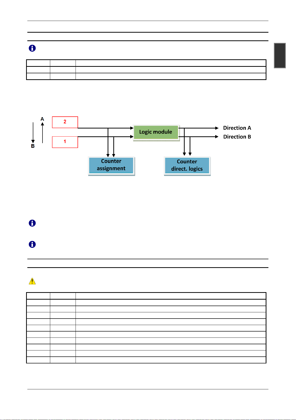
Complex algorithms have been integrated into the 2-channel detector to provide direction-dependent detection of vehicles on double-loops. The directional logic generates logic output signals that may be output via
the hardware outputs, depending on settings Simultaneously, the detector independently counts the logic
signals.
turned off (factory defaults)
GBR
In every logic, the loop that is covered first determines the count or direction of travel. For example, if loop 1
is covered first, the output is issued and the count in direction A is performed.
The factory default setting issues the output for the direction of travel A via hardware output 1 and for direction of travel B via hardware output 2. However, the assignment of the outputs may be changed.. (see chapter 11.8)
The service program Detector Tool displays the counters. It should be noted that the counters overflow
at 65535 (216) and are cleared automatically.
The counts in the detector are not protected against loss of power!
11.12 Direction Logic
Depending on the application, different evaluation logics can be selected in the logic module.
The adjustment of the direction of logic is possible only with activated direction detection!
DIP USB Direction Logic
OFF D2
D1 Continuous signal 1
DB Continuous signal, both loops
ON F1 Wrong-direction driver 1
F2 Wrong-direction driver 2
FE Feig
SF Loop free
BS both loops
PB Parking bay
OFF no logic selected
Continuous signal 2 (factory defaults)
FEIG ELECTRONIC GmbH 09/2015 19
Page 20

Manual VEK MNE1 / VEK MNE2
1
The following brief description refers to the different logics for direction detection.
Direction Logic Signal output Signal off Remark
D1 – continuous signal 1
DB – continuous signal
GBR
both loops
D2 – continuous signal 2 Coverage 2nd loop
F1 – wrong-direction
driver 1
F2 – wrong-direction
driver 2
BS – both loops
FE – Feig Exit 1st. loop
SF – loop free Exit 2nd.loop
PB – parking bay direction dependent For short entries and exits
Coverage 1st loop
Coverage 2nd loop
Exit 1st. loop
Exit 2nd. loop
Pulse output with
the selected minimum signal duration
(default 200ms)
Signal output in the opposite direction is active
again if both loops were previously free.
Correct behavior in slow-moving stop-start traffic and when maneuvering. Different behavior
for wrong direction driver situations.
Correct behavior for moving traffic maneuvering should not occur.
Correct behavior in slow-moving stop-start traffic and when maneuvering.
Detection of single vehicles and maneuvering
vehicles. Stop-start traffic should not occur
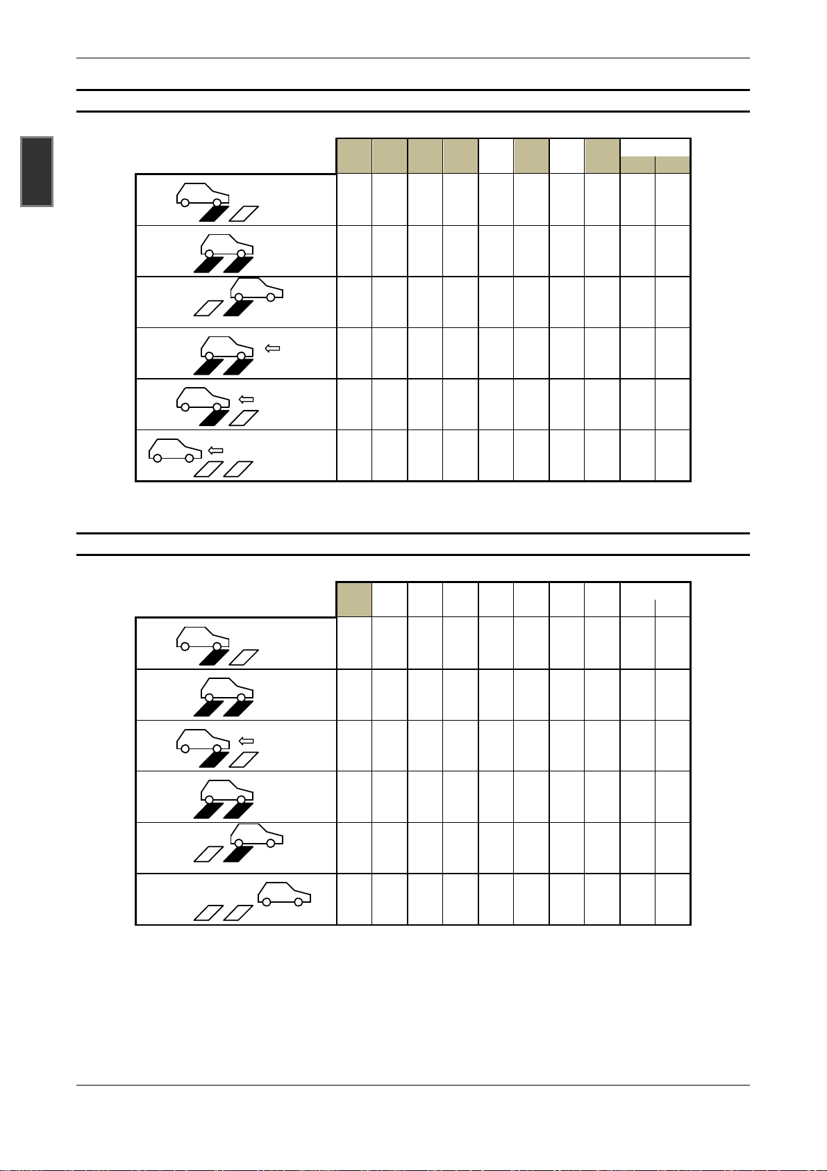
The detailed operation for various traffic situations is clearly shown by the following tables.
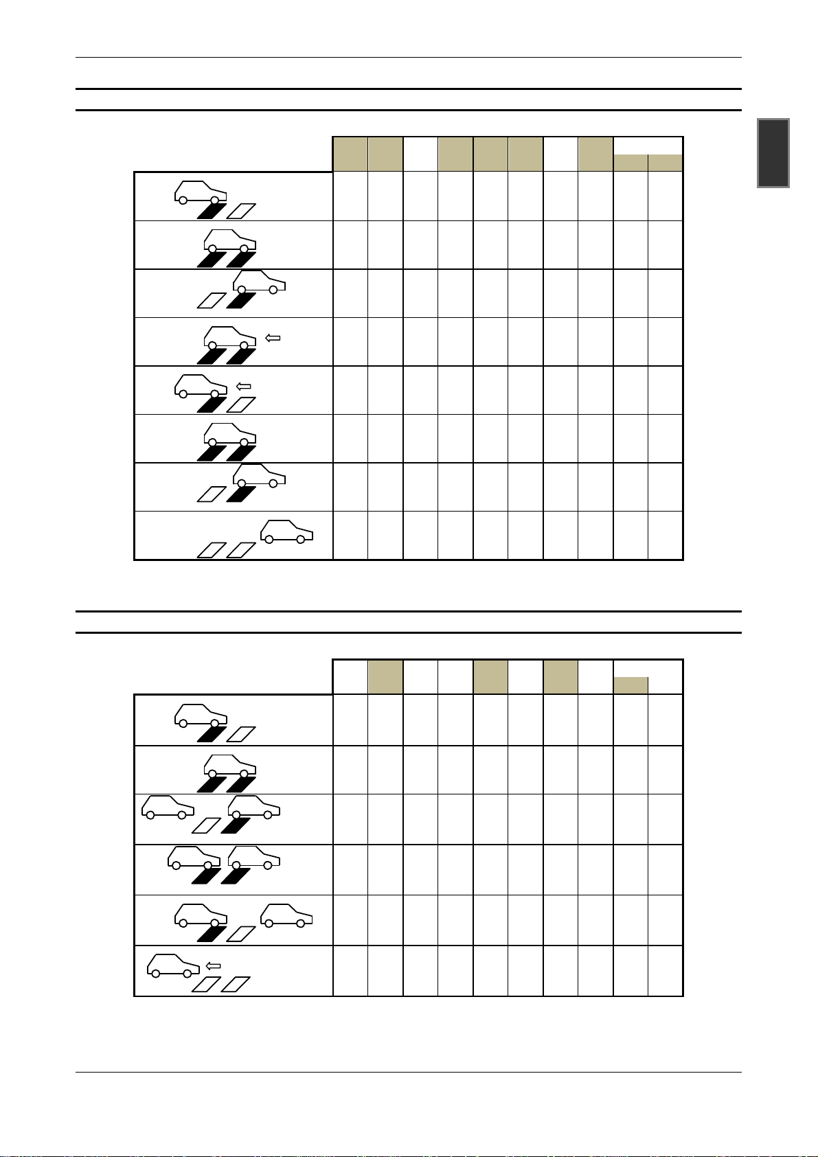
Explanatory Notes on the table:.
xx
marked direction logic xx = logic with miscounting for this traffic situation
___
Imp Pulsed signal traveling dir. A Imp Pulsed signal traveling dir. B
on continuous signal on off continuous signal off
1
Loop free Loop covered
11.12.1 Single vehicle
D2 D1 DB F1 F2 FE SF BS
PB
Ri1 Ri2
1 2
1 2
1 2
1 2
on
an
|
|
|
|
on |
|
|
|
|
| | Imp Imp Imp
|
|
|
off
|
Imp Imp
|
|
1 2
off
| off
Imp Imp
20 09/2015 FEIG ELECTRONIC GmbH
Page 21

Manual VEK MNE1 / VEK MNE2
11.12.2 Stop-start traffic
A
1 2
A
1 2
B A
1 2
B A
1 2
B A
1 2
B
1 2
B
1 2
1 2
B
D2 D1 DB F1 F2 FE SF BS
on
on |
|
|
|
on
|
| | Imp Imp Imp
|
|
|
|
|
|
off
|
Imp Imp
|
|
|
|
|
on
|
|
|
|
|
|
|
off
|
|
|
|
|
|
on
|
| | Imp Imp Imp
|
|
|
|
|
|
off
|
Imp Imp
|
|
|
off | off Imp Imp
PB
Ri1 Ri2
___
Imp
GBR
11.12.3 Wrong-direction driver 1
1 2
1 2
1 2
1 2
D2 D1 DB F1 F2 FE SF BS
on
on |
|
|
|
on
|
| | Imp Imp Imp
|
|
|
|
off
| off
|
|
|
|
|
|
___
___
off
Imp
Imp
PB
Ri1 Ri2
FEIG ELECTRONIC GmbH 09/2015 21
Page 22
Manual VEK MNE1 / VEK MNE2
11.12.4 Wrong-direction driver 2
GBR
1 2
1 2
1 2
1 2
1 2
1 2
D2 D1 DB F1 F2 FE SF BS
on
on |
|
|
|
on
|
| | Imp Imp Imp
|
|
|
|
|
|
off
|
Imp Imp
|
|
|
|
|
on
|
|
|
|
|
|
|
off
|
|
|
|
| off
|
off
___
Imp
PB
Ri1 Ri2
___
Imp
11.12.5 Maneuvering 1
D2 D1 DB F1 F2 FE SF BS
PB
Ri1 Ri2
1 2
on
on
1 2
|
|
off
1 2
on
1 2
|
|
1 2
|
|
|
off
1 2
on |
|
|
|
|
| | Imp Imp Imp
|
|
|
|
|
|
|
|
|
|
|
|
|
|
|
off
|
Imp Imp
|
| off
Imp
Imp
22 09/2015 FEIG ELECTRONIC GmbH
Page 23
Manual VEK MNE1 / VEK MNE2
11.12.6 Maneuvering 2
D2 D1 DB F1 F2 FE SF BS
PB
Ri1 Ri2
1 2
on
on
1 2
|
|
1 2
1 2
|
|
|
|
|
|
off
1 2
on
1 2
|
|
1 2
|
|
on |
|
|
|
|
| | Imp Imp Imp
|
|
|
off
|
Imp Imp
|
|
on
|
|
|
|
|
|
|
|
|
|
|
|
| | Imp Imp Imp
|
|
|
off
|
Imp Imp
|
___
Imp
|
1 2
off
| off
Imp Imp
11.12.7 Wrong direction driver in start-stop traffic
GBR
A
1 2
A
B A
B A
B A
B
1 2
1 2
1 2
1 2
1 2
D2 D1 DB F1 F2 FE SF BS
on
on |
|
|
|
on
|
| | Imp Imp Imp
|
|
|
|
|
|
off
|
Imp Imp
|
|
|
on
|
|
|
|
off
|
|
|
|
|
|
|
___
Imp
|
|
|
off
| off
___
PB
Ri1 Ri2
Imp
FEIG ELECTRONIC GmbH 09/2015 23
Page 24
Manual VEK MNE1 / VEK MNE2
(Straße)
(Straße)
11.12.8 Cross traffic
GBR
1 2
1 2
1 2
1 2
1 2
1 2
D2 D1 DB F1 F2 FE SF BS
on
on |
|
|
|
on
|
| | Imp Imp Imp
|
|
|
|
|
|
off
|
Imp Imp
|
|
|
|
|
on
|
|
|
|
|
|
|
off
|
|
|
|
| off
|
off
___
Imp
PB
Ri1 Ri2
___
Imp
All logics except for the logic PB in direction 1 supply in this traffic situation miscounts since they
count on instead of off signals!
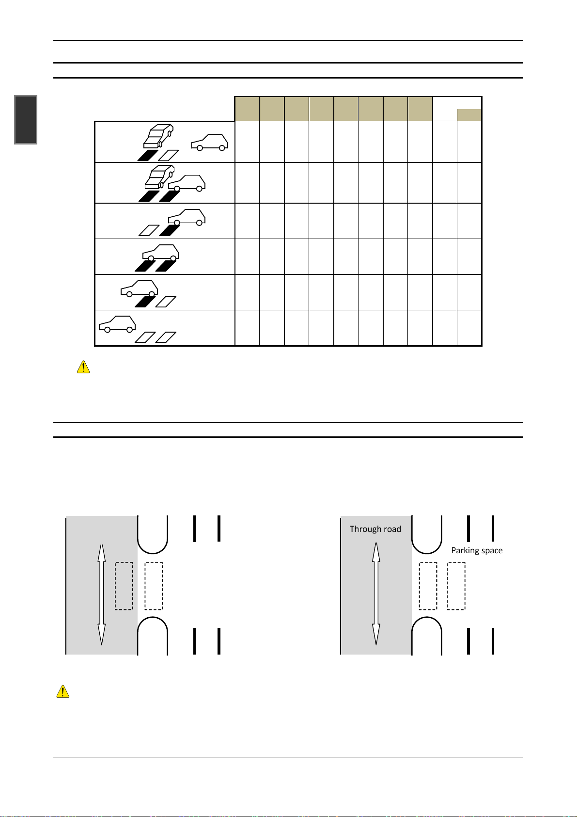
11.12.9 Direction Logics “Parking Bay”
This direction logic is used for short entries and exits. The impairment of the counting process by cross traffic
on loop 1 is suppressed in this logic. It is irrelevant whether loop 1 is placed into the through road or in the
maneuvering area.
Durchfahrt
Through road
1 2
Parking space
Parkraum
Durchfahrt
Parkraum
1 2
or
The placement of loops depends on the direction to be expected for start-stop situations. In traveling di-
rection 1 → 2 no tailback may occur! In the direction of travel 2 → 1, vehicles are also counted correctly
in start-stop situations, but it is necessary that the vehicle gap release one loop respectively.
24 09/2015 FEIG ELECTRONIC GmbH
Page 25

Manual VEK MNE1 / VEK MNE2
Logics when the direction of travel is 1 →→→→ 2
• The counting pulse occurs once both loops were completely crossed
• correct counting of single vehicles
• correct counting also when maneuvering
• Traffic jams and start-stop situations may not occur when the direction of travel is 1 -> 2 !
Logics when the direction of travel is 2 →→→→ 1
• The counting pulse occurs as soon as loop 2 is left in the direction of loop 1.
• Correct counting even with cross-traffic
• proper counting in start-stop traffic
• Correct counting also when maneuvering a single vehicle
• Maneuvering within a column must not occur!
GBR
FEIG ELECTRONIC GmbH 09/2015 25
Page 26

Manual VEK MNE1 / VEK MNE2
12 Notes
GBR
26 09/2015 FEIG ELECTRONIC GmbH
 Loading...