

Page 1
TST FSAM
Wireless Safety System for industrial
doors - Mobile Unit
Installation- and Startup manual
!
ATTENTION
The content of the door controller manual and particularly the safety instructions
must get note. The rules for Disposal of electronic parts and of the battery, insert
by customer, must get note.
FSAM
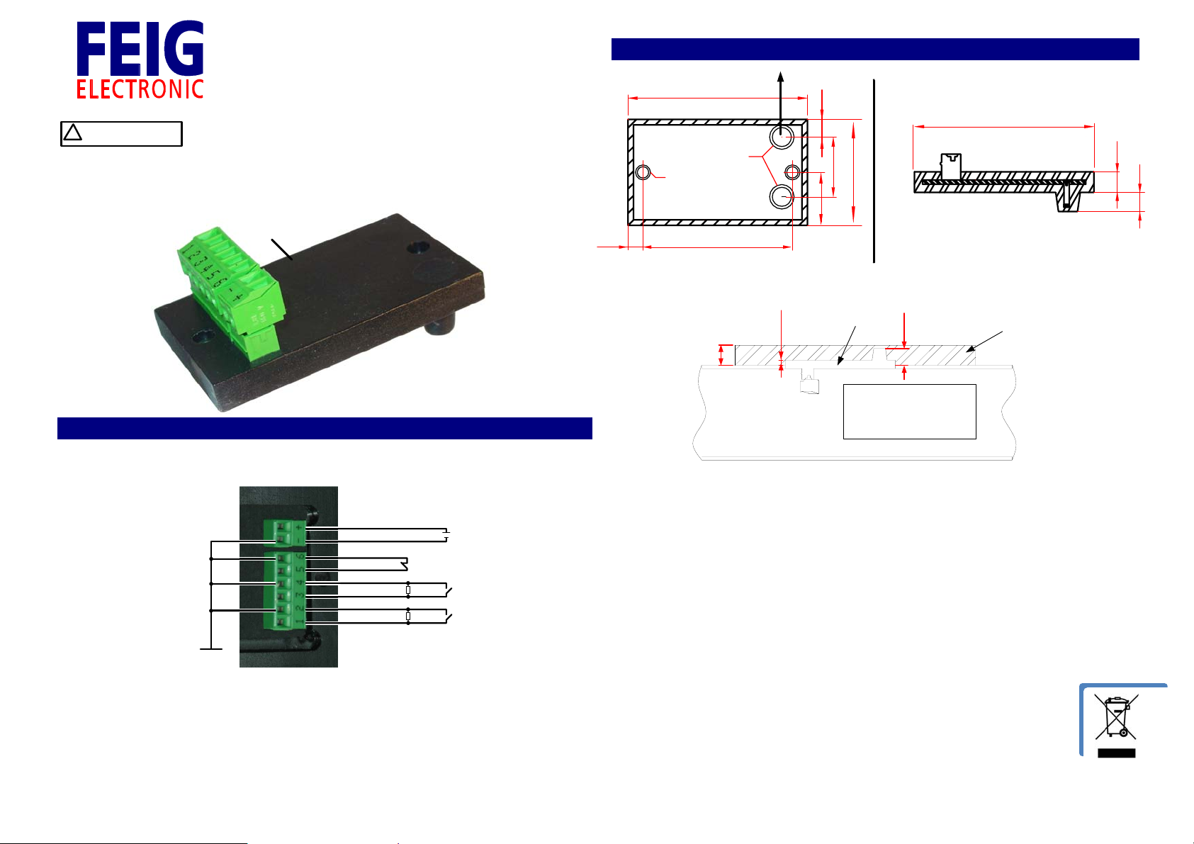
2. Installation of the mobile device:
directi on of t ransm i ssi on
66
D 8,5
D 4,2
555,5
6,5
22
39
19,5
66
7,5
7
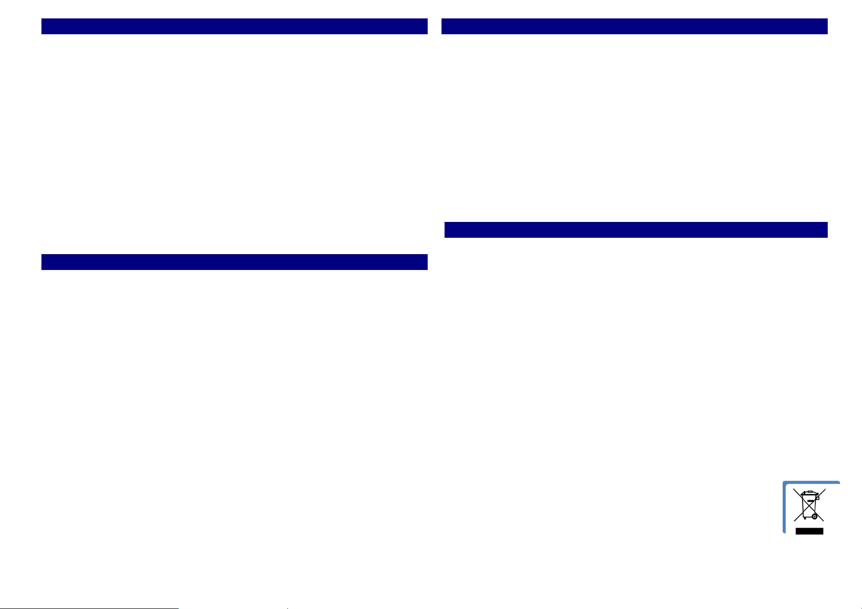
1. Pin connections:
Input 1 and 2 are normally open contacts with 8,2kΩ parallel resistor.
Input 3 is normally closed contact.
3,6 V
Input 3
Input 2
Input 1
Remark:
- Supply voltage of 3,6V with Thionyl Chloride Lithium battery e.g. XENO XL-
205F/19Ah.
- The battery is not part of the delivery .
Cr
Si2
Si1
12
profi l e inside
max 3
TST FSAM
10,5
battery
cover
Remarks:
- Get note of the assembling position. The marked direction of transmission
must show to the stationary antenna.
- To fixing of the mobile device in the cover can be done with M4 plastic
screws or it can be sticked. But then you have to look about glue in antenna
area. The plastic material of the cover must not have transmission loss at
2.4GHz (e.g. ABS, PC or Teflon without incorporation of conductive material
for coloring).
- The battery can be installed in the gate profile. Take care that the battery is
isolated completely in order to prevent Isolation damages because of for
doors typical vibrations or that the battery cover will not be damaged by
hard mechanical strikes.
- The electrical connection of the battery and the three Inputs must
be isolated against the gate profile.
FEIG ELECTRONIC GmbH Lange Str. 4 D-35781 Weilburg, Germany Tel.: +49 (0) 6471 / 3109-0 Fax: +49 (0) 6471 / 3109-99 www.feig.de Email:
info@feig.de
Page 2
3. Technical data:
Connection about plug-in terminal RM 3.81 mm
Supply voltage: 3.6V (3.2V to 4.0V), typical 8.5mA active / 0.5mA
inactive.
Inputs: Three configure able inputs with following standard
configuration:
- inputs 1 and 2: safety edge input (N.O.) with
8.2kΩ tested terminal resistor.
- Input 3: break away input (N.C.)
Temperature range: operating range –40°C to +70°C,
store range –40°C to +85°C
Operating frequency: 2400 to 2483.5MHz, 40 channels,
Rated output power 0dBm
Protection class: IP65 for sealed-in components on the board,
IP20 for terminals
Weight: 30g
lifetime of the battery: typical two years by using XENO XL-205F
Dimension (mm): ( L x B x H ) 68 x 38 x 7.6 +
antenna height 7mm + clamp
4. FCC Statements:
Notice: This device complies with Part 15 of the FCC Rules and with RSS-210 of Industry
Canada. Operation is subject to the following two conditions:
(1) this device may not cause harmful interference, and
(2) this device must accept any interference received, including interference that may
cause undesired operation.
Notice: Changes or modifications made to this equipment not expressly approved by
FEIG ELECTRONIC may void the FCC authorization to operate this equipment.
Notice: This product has been tested and found to comply with the limits for a Class B
digital device, pursuant to part 15 of the FCC Rules. These limits are designed to provide
reasonable protection against harmful interference in a residential installation. This
equipment generates uses and can radiate radio frequency energy and, if not installed
and used in accordance with the instructions, may cause harmful interference to radio
communications. However, there is no guarantee that interference will not occur in a
particular installation. If this equipment does cause harmful interference to radio or
television reception, which can be determined by turning the equipment off and on, the
user is encouraged to try to correct the interference by one or more of the following
measures :
- Reorient or relocate the receiving antenna
- Increase the separation between the equipment and receiver
- Connect the equipment into an outlet on a circuit different from that to which
the receiver is connected
- Consult the dealer or an experienced radio / TV technician for help
5. Startup manual of the gate control:
Extract from startup manual:
Configuration parameters for wireless safety edge:
- P.46B = 1 Activates the drive on delay of the door until the safety edge is
active and the evaluation works.
- P.46C = 1000ms Sets the maximum time in which the wireless edge has to be active
for a flawless drive start of the door.
- P.F00 = 1 Activates the wireless edge.
- P.F01 = 20ms Sets the timeout for the wireless edge. If the edge is not answering
within the adjusted time the edge will recognized as released. (Edge 1 and 2).
- P.F04 = 0
0 = The mobile device will only wake up if necessary (Energy saving mode).
1 = The digital radio link is always active.
- P.F05 = x Choice of radio channel group of mobile device (x = 1 … 10).
- P.F06 = x Shows the used radio channel
- P.F07 = xxx Sets the address of the wanted mobile partner of the controller.
- P.F08 = 3.0V Sets the value for the battery voltage under which the error
message F.856 will be shown.
5. Error messages:
- F.852 No RS485 data traffic between the controller and the stationary device in
the TST PDFSAS device for min. 1 second.
Possible Causes:
- Stationary device not connected or no supply voltage.
- Stationary radio device inside the encoder defective or disturbed.
- Interface cable defective (In this case you can also see F752 in
combination).
- F.856 Error of the digital radio link. No radio connection between both partners for
more than 10 seconds.
Possible Causes:
- No mobile device found
- Too low supply voltage of mobile device (Battery empty).
- Set address is wrong
- Antenna not connected or unfavorable mounted
- Strong disturbances on the used frequency range
- F.857 This error is shown if the value of the voltage falls under the limit set with
P.F08 (Battery monitoring
).
FEIG ELECTRONIC GmbH Lange Str. 4 D-35781 Weilburg, Germany Tel.: +49 (0) 6471 / 3109-0 Fax: +49 (0) 6471 / 3109-99 www.feig.de Email:
info@feig.de
 Loading...