

Page 1
Operating Instructions
Digital Counter - VEK CN1-1
Stand: 07.12.11 as/ws
BES_CN1-1_2011_12_07_GB.doc
Page 2

Operating Instructions VEK CN1-1
Note
© Copyright 2011 by FEIG ELECTRONIC GmbH
Lange Straße 4
D - 35781 Weilburg
The specifications contained in this document may be changed without prior notice.
This edition replaces all earlier editions of the document.
The information in this guide has been compiled to the best of our knowledge and in good faith. FEIG
ELECTRONIC assumes no liability for the accuracy of the specifications in this guide. In particular FEIG
ELECTRONIC cannot be held liable for consequential damages resulting from improper installation.
Since errors can never be completely precluded in spite of all our efforts, we are always grateful for
corrections and suggestions.
The installation recommendations contained in this guide assume the most favorable circumstances.
FEIG ELECTRONIC assumes no liability for perfect function of the traffic detector in a foreign system
environment.
Photocopying and reproduction of this guide in whole or in part as well as translation into other
languages is not permitted without prior written permission from FEIG ELECTRONIC. Also prohibited is
storage of this guide in whole or in part on modern storage devices for the purposes of further
processing in data processing systems.
Please read these operation instructions prior to install the equipment!
2 12/11 FEIG ELECTRONIC GmbH
Page 3

Operating Instructions VEK CN1-1
Table of Contents
1 Functional Description _____________________________________________________________ 4
1.1 General _____________________________________________________________________________ 4
1.2 Operating Modes _____________________________________________________________________ 5
1.2.1 Operating Mode “OPEN SPACE COUNTING” _________________________________________________ 5
1.2.2 Operating Mode “PASSING VEHICLE COUNTING” ____________________________________________ 5
1.3 Pulse Inputs _________________________________________________________________________ 5
1.4 Reset Input __________________________________________________________________________ 5
1.5 Relay Output ________________________________________________________________________ 6
1.6 State Storage during Voltage Breakdown _________________________________________________ 6
2 Display and Setup _________________________________________________________________ 7
2.1 Display during normal operation _______________________________________________________ 7
2.2 User Interface Buttons ________________________________________________________________ 7
2.3 Base Menu __________________________________________________________________________ 7
2.3.1 Power Failure ____________________________________________________________________________ 7
2.3.2 Modify/Correct Counter ____________________________________________________________________ 8
2.3.3 Set Relay Output manually to “Free” or “Occupied” ______________________________________________ 8
2.3.4 Display and Counter Reset __________________________________________________________________ 8
2.3.5 Reset all Counter _________________________________________________________________________ 8
2.4 System Menu – Installation specific Settings ______________________________________________ 9
2.4.1 Operating Modes switching threshold _________________________________________________________ 9
2.4.2 Counter Hysteresis _______________________________________________________________________ 10
2.4.3 Counter Level ___________________________________________________________________________ 10
2.4.4 Display / Input settings ____________________________________________________________________ 11
2.4.5 Output settings __________________________________________________________________________ 11
2.4.6 Power Saving Mode ______________________________________________________________________ 12
2.5 Factory Setting _____________________________________________________________________ 12
3 Installation Instructions ___________________________________________________________ 13
3.1 Input voltage _______________________________________________________________________ 13
3.2 Wiring of Relays Outputs _____________________________________________________________ 14
4 Technical Data __________________________________________________________________ 14
5 Safety instructions and Warnings ___________________________________________________ 15
FEIG ELECTRONIC GmbH 12/11 3
Page 4
Operating Instructions VEK CN1-1
1 Functional Description
1.1 General
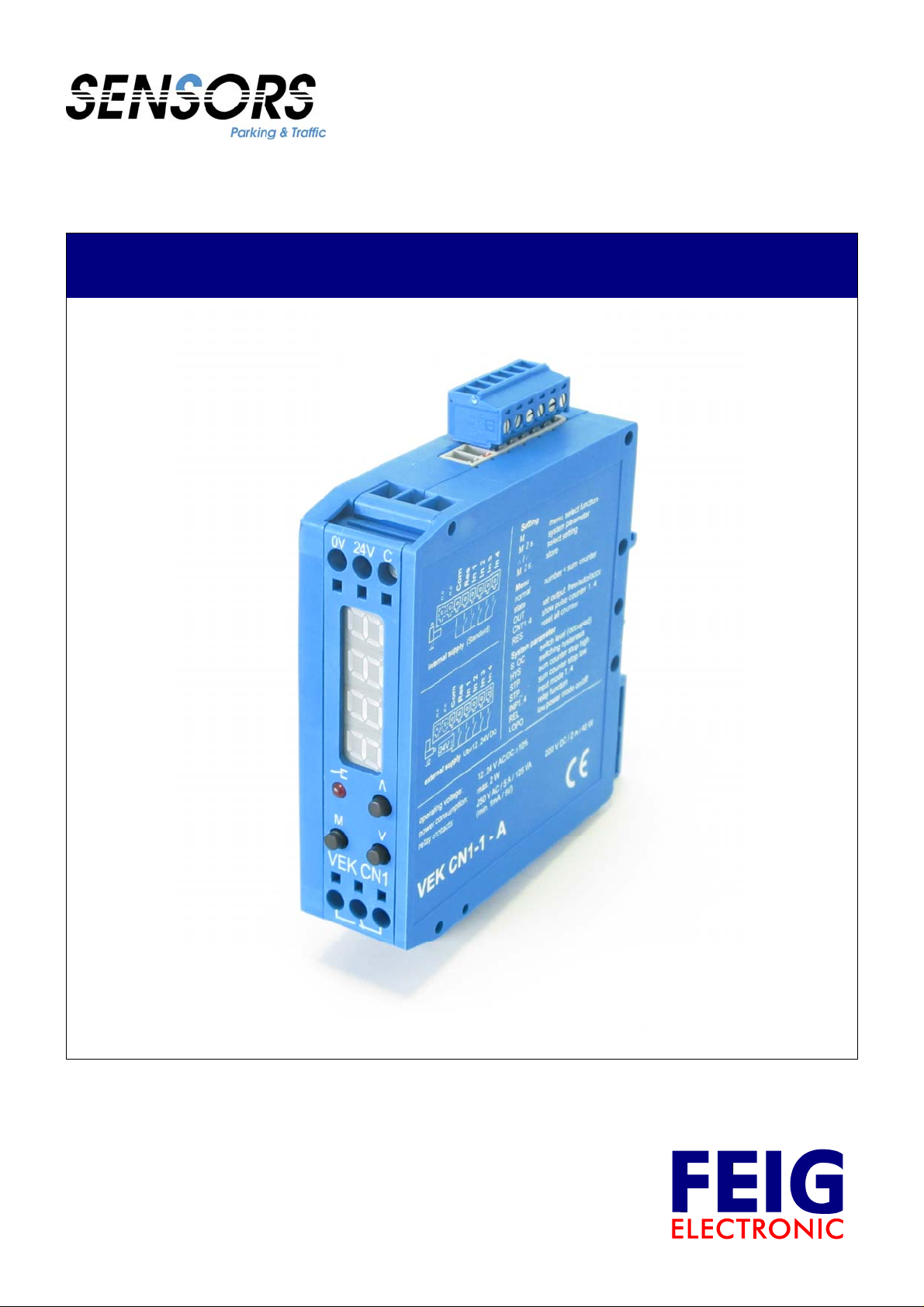
6-pin plug: 4 Counting Inputs, Reset Input, Common
↓
0V 24V C
V
M
V
VEK CN1
The digital counter VEK CN1 is designed to control small medium car-parks. Four counting inputs are used to
accept outputs from loop detectors and/or traffic gate controllers. The counting inputs increment or decrement the
counter and is displayed on the 4-digit display. The output relay is used to turn on/off traffic signs or lot full signs.
Available open space counter and counter hysteresis are adjustable. The output relay can be used to directly
control a traffic light or a lot full sign.
Characteristics
• Especially developed for small to medium car-parks
• Vehicle counter and open space counter
• 4-digit display
• Totalize counter -999 … 9999
• 4 universal inputs with noise suppression
• Inputs function individually adjustable for increment, decrement or reset
• 1 reset input
• 1 relay output 150V, 5A for traffic lights and lot full signs (or others)
• Output function is adjustable for automatic, permanent free, permanent occupied
• Relay is adjustable to normally open or normally closed mode
• LED to display relay status
• 4 independent input counter up to 9,999,999 for statistical use independently displayed
• Available open space counter and counter hysteresis are adjustable
• Upper and lower counter threshold is adjustable
• 3 push buttons for user interface
• Power Supply 12..24 V DC/AC
• No loss of current data storage in case of power failure
• Display of temporary power failure
• Compact plastic housing 0.88 ” (22,5 mm) x 3.15 ” (80 mm) x 3.35 ” (85 mm), with DIN-Rail mounting
4 12/11 FEIG ELECTRONIC GmbH
Page 5

Operating Instructions VEK CN1-1
1.2 Operating Modes
The counting unit can be operated in mode “Open Space Counting” or in mode „Passing Vehicle Counting“. The
choice of operating mode occurs with set up the switching threshold. (see 2.4.1 Operating Modes switching )
Operating
Mode
Open Space
Counting
Passing vehicle
Counting
S_oc = adjusted switching Threshold (switch occupied)
hys = adjusted Counter Hysteresis (see 2.4.2 Counter Hysteresis)
set to switching
threshold
Requested value
S oc
0
≤ (S oc – HyS)
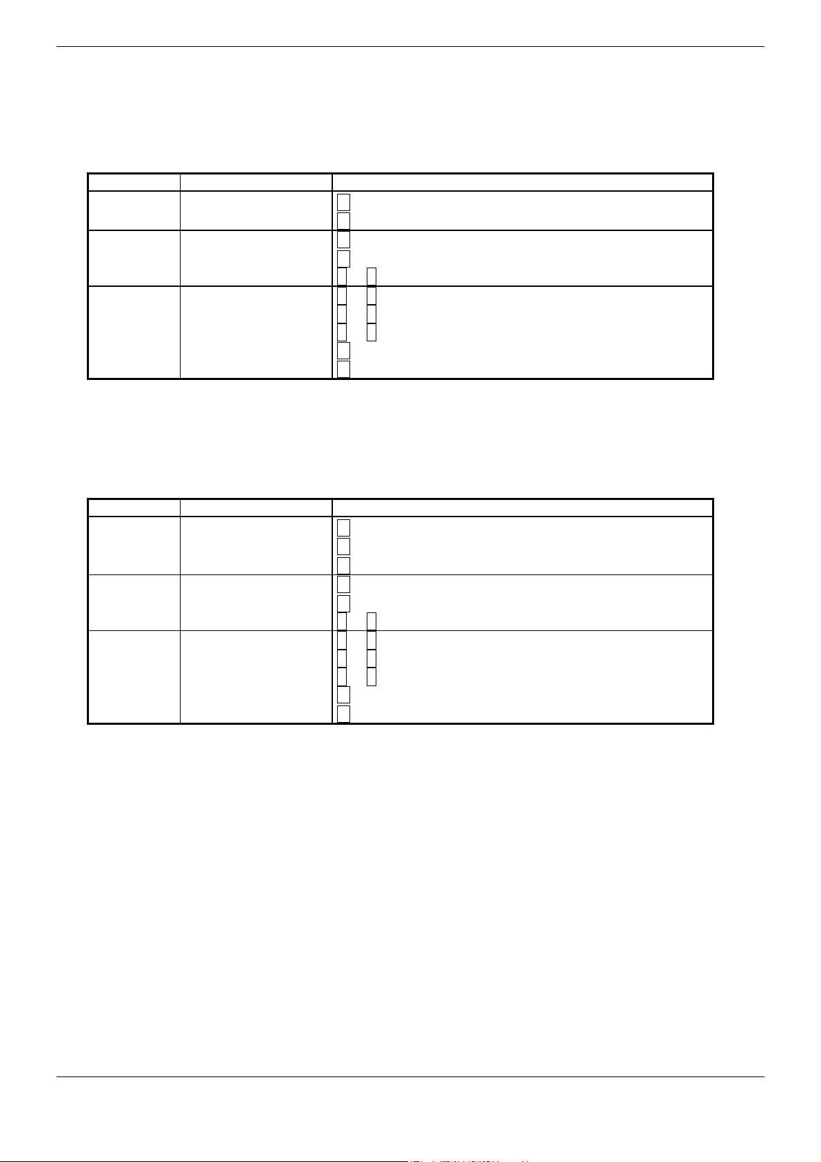
1.2.1 Operating Mode “OPEN SPACE COUNTING”
The “OPEN SPACE COUNTING” is preferably used when the counting reading of the parking spaces is done
when the car-park is full so less open spaces has to be counted. Vehicles leaving the car-park will increment the
counter (Input 1) and vehicles entering the facility will decrement the counter (Input 2). The counter will activate the
output relay whenever the open space counter is equal or less than “0”. The output relay will be released as soon
the counter reached the adjusted counter hysteresis.
Output relay switches
at counter
reading
≤ 0
≥ HyS
S oc
≥
on output state
used
free
used
free
1.2.2 Operating Mode “PASSING VEHICLE COUNTING”
The “PASSING VEHICLE COUNTING” is preferably used when the counter reading of the parking spaces is done
when the car-park is empty so less occupied parking spaces must be counted. Vehicles entering the car-park will
increment the counter (input 1) and vehicles leaving the facility will decrement the counter (input 2). The counter
will activate the output relay whenever the vehicle counter reaches or is higher than the adjusted maximum. The
output relay will be released as soon the counter reaches or is lower than the adjusted lower counter hysteresis.
1.3 Pulse Inputs
The switching status of inputs is in normal operating mode displayed with four decimal points on the display. The
function of Inputs can be independent set on:
• increment
• decrement
• reset counter or
• no function
(see 2.4.3 Counter Level). Factory setting for input 1 and 3 is set to increment and for input 2 and 4 set to
decrement.
The inputs are interference-suppressed against switch bounces. Input pulses are counted separately of adjusted
function until 9.999.999. Each input pulse counter can be set up and reset separately. (see 2.3.4 Display and
Counter Reset).
1.4 Reset Input
With the Reset Input the counter reading can be reset to 0. The relay output will be adequate to the preferences set
on free or used. The adjustment parameters and the input pulse counter will not be changed. Is the output state
manually set on free or used (see 2.3.3 Set Relay Output manually to “Free” or “Occupied”) so the relay will stay in
this state.
FEIG ELECTRONIC GmbH 12/11 5
Page 6

Operating Instructions VEK CN1-1
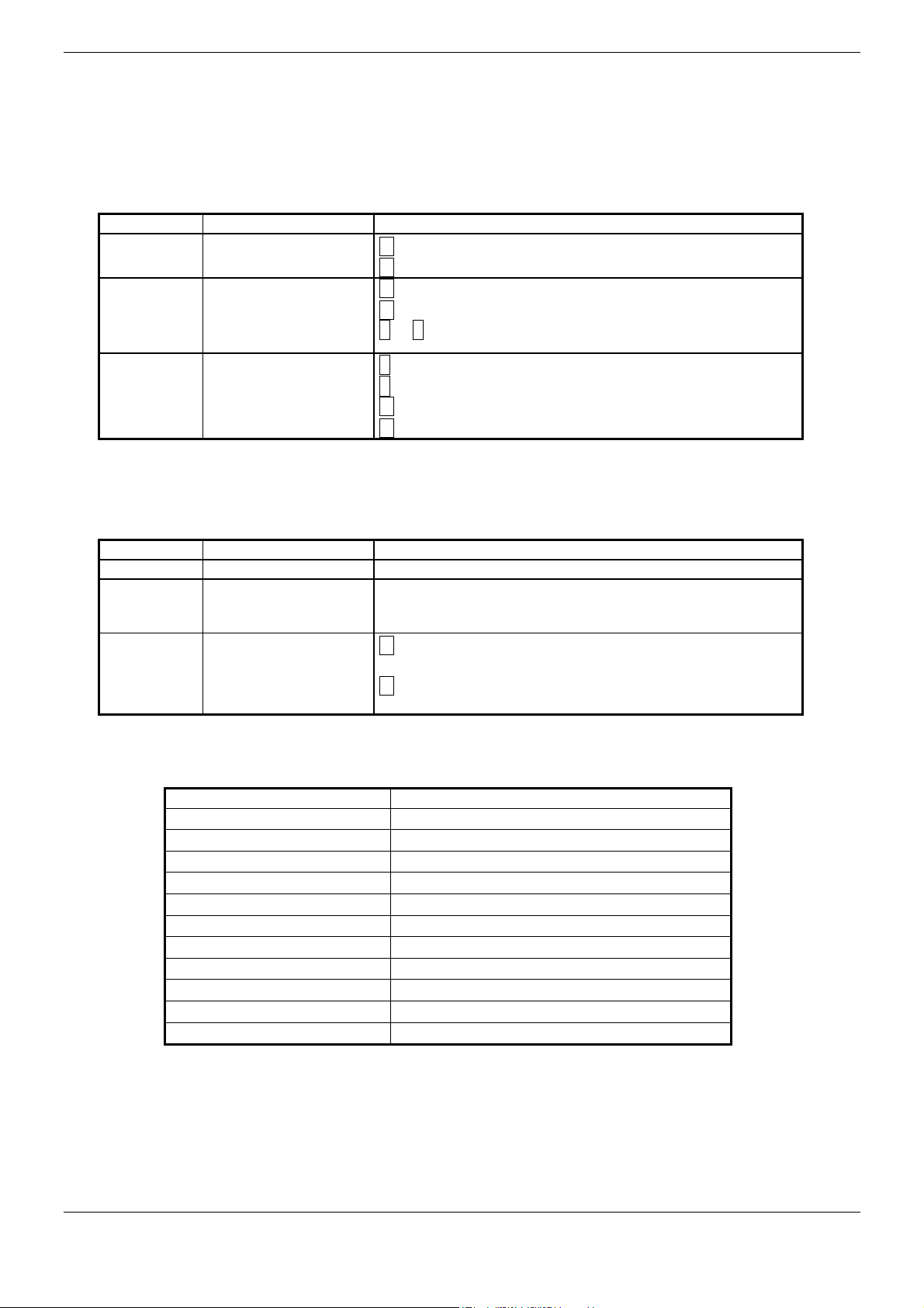
1.5 Relay Output
The relay output signals „Free Parking Area“ or “Used Parking Area”. The relay changeover contact can directly
control a traffic light. The method of operating for the relay can be set on load current principle or rest current
principle (see 2.4.5 Output settings). The LED displays the status of the relay.
Output Status Relay Operating
Principle
Free Load Current Principle energized Off
Used Load Current Principle de-energized On
Free Rest Current Principle de-energized On
Used Rest Current Principle energized Off
If the operating of the output isn´t used, the output state can be manually set on „always free“ or „always used“
(see 2.3.3 Set Relay Output manually to “Free” or “Occupied”).
Relay LED
1.6 State Storage during Voltage Breakdown
During voltage breakdowns the setting values and the counter states remain unchanged. After the voltage returns
the counter works on normally. A flashing display shows the counter state must be checked and maybe fixed (see
2.3.1 Power Failure).
6 12/11 FEIG ELECTRONIC GmbH
Page 7
Operating Instructions VEK CN1-1
2 Display and Setup
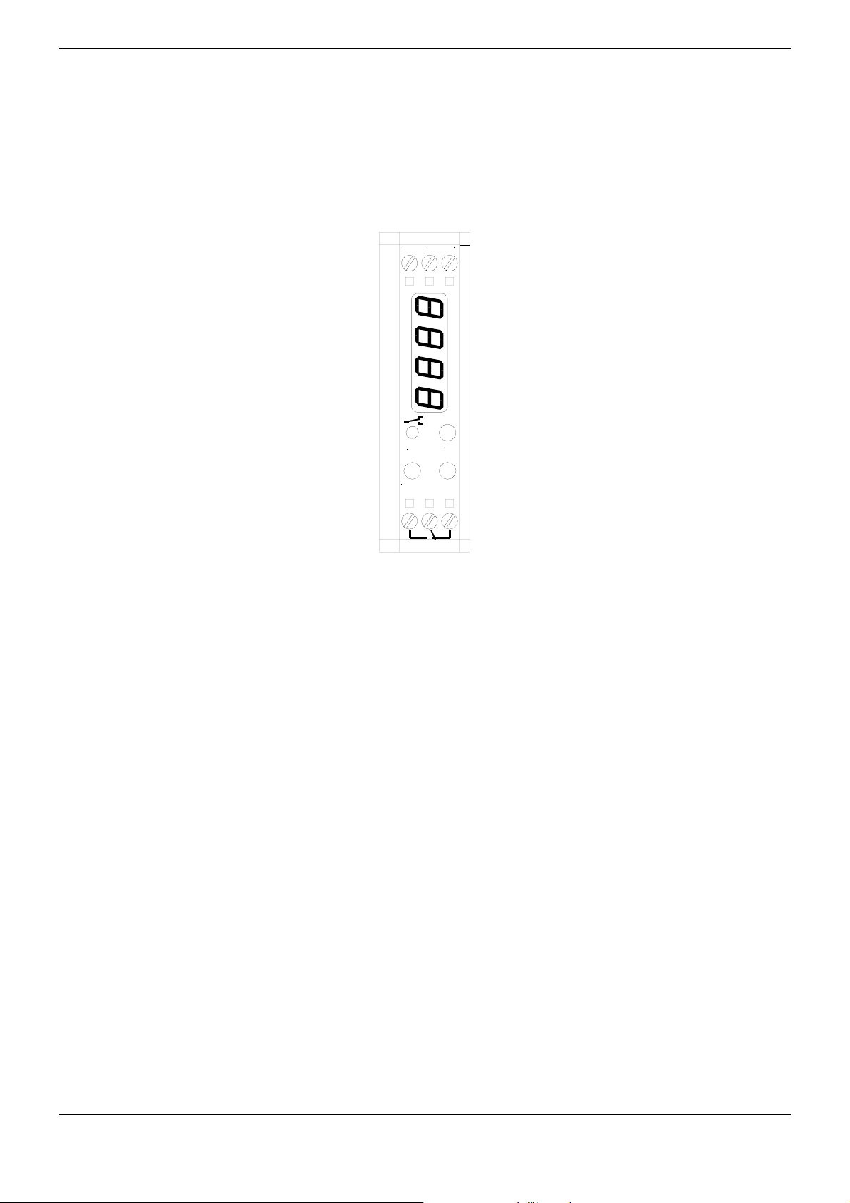
2.1 Display during normal operation
In normal operating mode you can have the display show either how many vehicles entered the car-park or how
many open spaces are left (see 1.4.1 Operating Mode/Switching point). The relay status is displayed with the LED.
Input states are indicated with the 4 dots in the display. Special states of the counting unit are shown directly.
Display
Number, for example 1234
Number, all 4 numbers flashing temporary voltage breakdown occurred
Number /occu , alternating
Number /FrEE , alternating
0000
Dots Input Status, left to right 1,2,3,4
LED on/off Output relay status: activated = on/deactivated = off
Display off,
if unit was idle for 30 s
State
Normal operation, Current counter
Current counter, Output manually set to “occupied”.
Current counter, Output manually set to “free”.
Reset Input active (optional)
Power save mode
2.2 User Interface Buttons
The VEK CN1 digital counter is adjusted with three user interface buttons located on top of the unit. The display
shows the current menu and state of the setup. The buttons have following functionality:
Button Function
M
(Mode) Long Activate System menu, Save changes, exit menu.
(Up) Long Display value, fast increment
(Down) Long Display value, fast decrement
Two simultaneously Cancel changes, back to operating mode.
The menu navigation is divided in a base menu and a system menu. During setup the flashing display signalizes
that the settings aren’t saved yet. If the unit was idle for 30 s the unit goes back to normal operating mode without
saving changes.
Short Next Menu, next digit, Cancel settings.
Short Display value, increment + 1
∧
Short Display value , decrement – 1
∨
2.3 Base Menu
The base menu contains all settings for the different operating modes. The existing counts can be displayed,
modified and reset the original stage. The relay output can be manually set to “FREE” or “OCCUPIED”
Display
1234
Ouk
Cnk1
Cnk2
Cnk3
Cnk4
rES
Menu Setting
Normal Operation, Current Counter
Relay output manually
Input 1
Input 2
Input 3
Input 4
Reset all Counter
M Short → next, next menu item
Two buttons simultaneously or
M long →End =back normal operation
∧ or ∨ →change
M long →save
2.3.1 Power Failure
Display Status Setting
1234
(flashing)
FEIG ELECTRONIC GmbH 12/11 7
Return after power
failure
∧ or ∨ → update open space counter
M →confirm existing counter
Page 8
Operating Instructions VEK CN1-1
2.3.2 Modify/Correct Counter
Display State Settings
1234
1234
one digit
flashing
Normal Operation
Modify Counter
∧ or ∨ → First digit flashing → modify counter
∧ or ∨ → Digit + / - 1
∧ or ∨ 1 sec. → Fast scroll
∧ or ∨ 3 sec. → 10´s → 100´s → 1000´s
M short → 100´s → 10´s → 1´s → Cancel
M long →Skor = saved
2.3.3 Set Relay Output manually to “Free” or “Occupied”
If, for any reasons, the relay output needs to be disabled the output can be manually set to maintain either the
always “FREE” or always “OCCUPIED” state.
Display
1234
Ouk
Auko
occu
FrEE
(alternating)
Auko
occu
FrEE
(flashing)
State Settings
Normal Operation
Output Status display
• Automatic
•
Occupied
•
Free
Select Output status
M 1 x short →
Ouk = Output status display
M short → next, next menu item
M long →End = back to normal operation
∧ or ∨ → select output state
∧
→FrEE → Auko → occu
∨ →occu → Auko → FrEE
M short → cancel changes
M long →Skor = Output state saved
2.3.4 Display and Counter Reset
The inputs can individually count up to 9,999,999 and can individually be displayed or if necessary reset to zero.
Display
1234
State Setting
Normal Operation
M 2 x short →
Cnk1 = Input counter 1
:
Cnk4 = Input counter 4
Cnk1 ...4
1234
(alternating)
Cnk1 ...4
1234
.456
.
display current
counter
0...9999
display input counter
10.000...9.999.999
M 5 x short →
M short → continue, next menu item
∧ → current input counter
∨ → start input counter reset
(continuously)
0 flashing
Reset
M long →
Skor = reset input counter
M short → cancel reset
Note:
1. The open space or quantity of passed vehicle counter will not be affected during reset of any of the input
counter!
2. If display of one input counter is activated, it will not switch back to normal operating display by itself.
2.3.5 Reset all Counter
The open space and passed vehicle counter as well as the four (4) input counter can be reset at ones using the
following menu:
Display
1234
rES
State Setting
Normal operation
Menu item Reset
M 6 x short →
rES = Reset menu
M long → reset all counter
M short → back to normal operation without reset
8 12/11 FEIG ELECTRONIC GmbH
Page 9

Operating Instructions VEK CN1-1
2.4 System Menu – Installation specific Settings
In the system menu all installation specific settings can be made.
Display
1234
S oc
1234
(alternating)
HYS
1234
(alternating)
StP~
1234
(alternating)
StP_
-123
(alternating)
inP1 ...4
(alternating)
Add
Sub
rEs
no.F
rEL
(alternating)
oc.on
Fr.on
LoPo
(alternating)
off
On
Menu Item Setting
Normal Operation
Switch threshold
0...9999
Counter hysteresis
1...250
Upper counter threshold
0...9999
Lower counter threshold
0...-999
Input functions
• Increment counter
• Decrement counter
• Reset counter
• No function
Output function
• Normally closed
• Normally open
Power Save Mode
• off (Display on)
• on (Display off)
M long→ Display
alternating shows program version; for example A02
M short → next menu item
∧ or ∨ → change
M long → save
Two buttons simultaneously or
M long →
SYS = System menu
End = back in normal operation
2.4.1 Operating Modes switching threshold
The digital counter can be set to operating mode “OPEN SPACE COUNTING” or “PASSING VEHICLE
COUNTING”. Two options can be selected by setting the counter threshold to:
Threshold = 0 →Operating Mode “OPEN SPACE COUNTING” (see 1.2.1)
Threshold = 1..9999 →Operating Mode “PASSING VEHICLE COUNTING” (see 1.2.2)
Display
1234
S oc
1234
(alternating)
1234
(one digit
flashes)
State Setting
Normal Operation
Display Counter
Threshold
Change Threshold
0...9999
M long →
M short → next, next menu item
M long →End = back to normal operation
∧ or ∨ → change threshold
∧ or ∨ → Digit + / - 1
∧ or ∨ 1 sec. → fast scroll
∧ or ∨ 3 sec. → 10´s → 100´s → 1000´s
M short → 100´s → 10´s → 1´s → cancel
M long →Skor = save
SµS → S oc = threshold
FEIG ELECTRONIC GmbH 12/11 9
Page 10
Operating Instructions VEK CN1-1
2.4.2 Counter Hysteresis
With the counter hysteresis you can set the amount of vehicles that have to leave the facility after the “OPEN
SPACE COUNTING” or the “PASSING VEHICLE COUNTING” have reached the maximum and triggered the
output relay. Factory default is 0.
Display
1234
State Setting
Normal Operation
M long →
SyS → S oc
M 1 x short →HyS = counter hysteresis
HYS
1234
(alternating)
1234
(one flashing
digit)
Display counter
hysteresis
Change counter
hysteresis
1...9999
M short → continue, next menu item
M long →End = back to normal operation
∧ or ∨ → change threshold
∧ or ∨ → Digit +/- 1
∧ or ∨ 1 sec. → fast scroll
∧ or ∨ 3 sec. → 10´s → 100´s → 1000´s
M short → 100´s → 10´s → 1´s → cancel
M long →Skor = save
2.4.3 Counter Level
The maximum and minimum range of the total counter can be adjusted using this menu. This enables the counter
to automatically adjust the total in case the maximum or minimum level reached to prevent an incorrect counter to
continue. The default is 9999 for upper and -999 for the lower level.
Display
1234
SkP~ / _
1234
(alternating)
1234
(one flashing
digit)
State Setting
Normal operation
Display counter level
Change counter level
0...9999
M long →
SµS → S oc
M 2 x short →SkP~ = upper level 0…9999
M short →SkP_ = lower level -999…0
M short → continue, next menu item
M long →End = back to normal operation
∧ or ∨ → change counter level
∧ or ∨ → Digit +/- 1
∧ or ∨ 1 sec. → fast scroll
∧ or ∨ 3 sec. → 10´s → 100´s → 1000´s
M short → 100´s → 10´s → 1´s → cancel
M long →Stor = save
10 12/11 FEIG ELECTRONIC GmbH
Page 11

Operating Instructions VEK CN1-1
2.4.4 Display / Input settings
Independent from each other the inputs can set to:
• Incrementing
• Decrementing
• Reset Counter
• No function
Display
1234
inP1 ...4
(alternating)
Add
Sub
rEs
no.F
Add
Sub
rEs
no.F
Factory default is incrementing for input 1 and 3 and decrementing for input 2 and 4.
State Setting
Normal operation
Display input function
1 to 4
• Incrementing
• decrementing
• Reset count
• No function
Change function
(flashing)
M long →
M 4 x short →InP1 = function Input 1
M short → next Input, net menu item
M long →End = return to normal operation
∧ or ∨ → change function
∧ →no.F → rEs →Sub →Add
∨ →Add → Sub →rEs →no.F
M short → cancel
M long →Skor = save
SyS → S oc
2.4.5 Output settings
The output relay can be adjusted to Normally Open (NO) or Normally Closed (NC):
Display
1234
rEL
(alternating)
Fr.on
oc.on
Fr.on
oc.on
Factory default is Normally Open mode for the output relay.
State Setting
Normal Operation
Display Relay function
• If free NC
• If full NC
Change Relay function
(flashing)
M long →
M 8 x short →rEL = relay function
M short → next, next menu item
M long →End = return to normal operation
∧ or ∨ → change function
∧ →Fr.on → oc.on
∨ →oc.on → Fr.on
M short → cancel
M long →Skor = save
SyS → S oc
FEIG ELECTRONIC GmbH 12/11 11
Page 12
Operating Instructions VEK CN1-1
2.4.6 Power Saving Mode
If the Power Saving Mode is activated the display turns off if there was no activity on the user interface for more
than 30 s. The counter function continues to run in the background. The Power Saving Mode can be adjusted using
thefollowing menu:
Display
1234
LoPo
(alternating)
off
on
off
on
State Setting
Normal Operation
Display Power Saving
Mode
• OFF(Display on)
• ON (Display off)
Change Function
(flashing)
M long →
M 9 x short →LoPo = power saving mode
M short → next, next menu item
M long →End = return to normal operation
∧ or ∨ → change function
∧ →off → on
∨ →on → off
M short → cancel
M long →Skor = save
SyS → S oc
2.5 Factory Setting
All parameter and counter can be reset to factory default values using the following procedure:
Display
1234
(flashing)
Err
(flashing)
After a reset to factory default values all parameters are set to the following (see table below) and all counter are
set to zero (0).
State Setting
Turn off power supply for more than 2 seconds
Return after power
failure
System error
Parameter Setting
Press two buttons simultaneously →
M long →
→0000 flashing = factory default
M short → cancel, restart without factory default
settings
Skor = reset to factory default
Err
Ouk Relay output Auko Automatic
S oc Switch threshold 0 0 = Open Space Counting
HyS Counter hysteresis 1 one vehicle
SkP¯ Upper counter level 9999 9999
SkP_ lower counter level -999 -999
InP1 Function Input 1 Add incrementing
InP2 Function Input 2 Sub decrementing
InP3 Function Input 3 Add incrementing
InP4 Function Input 4 Sub decrementing
rEL Output functionality oc.on Normaly Open Mode
LoPo Power Save Mode oFF off, Display continuously activated
12 12/11 FEIG ELECTRONIC GmbH
Page 13
Operating Instructions VEK CN1-1
-
+
m
c
c
c
c
3 Installation Instructions
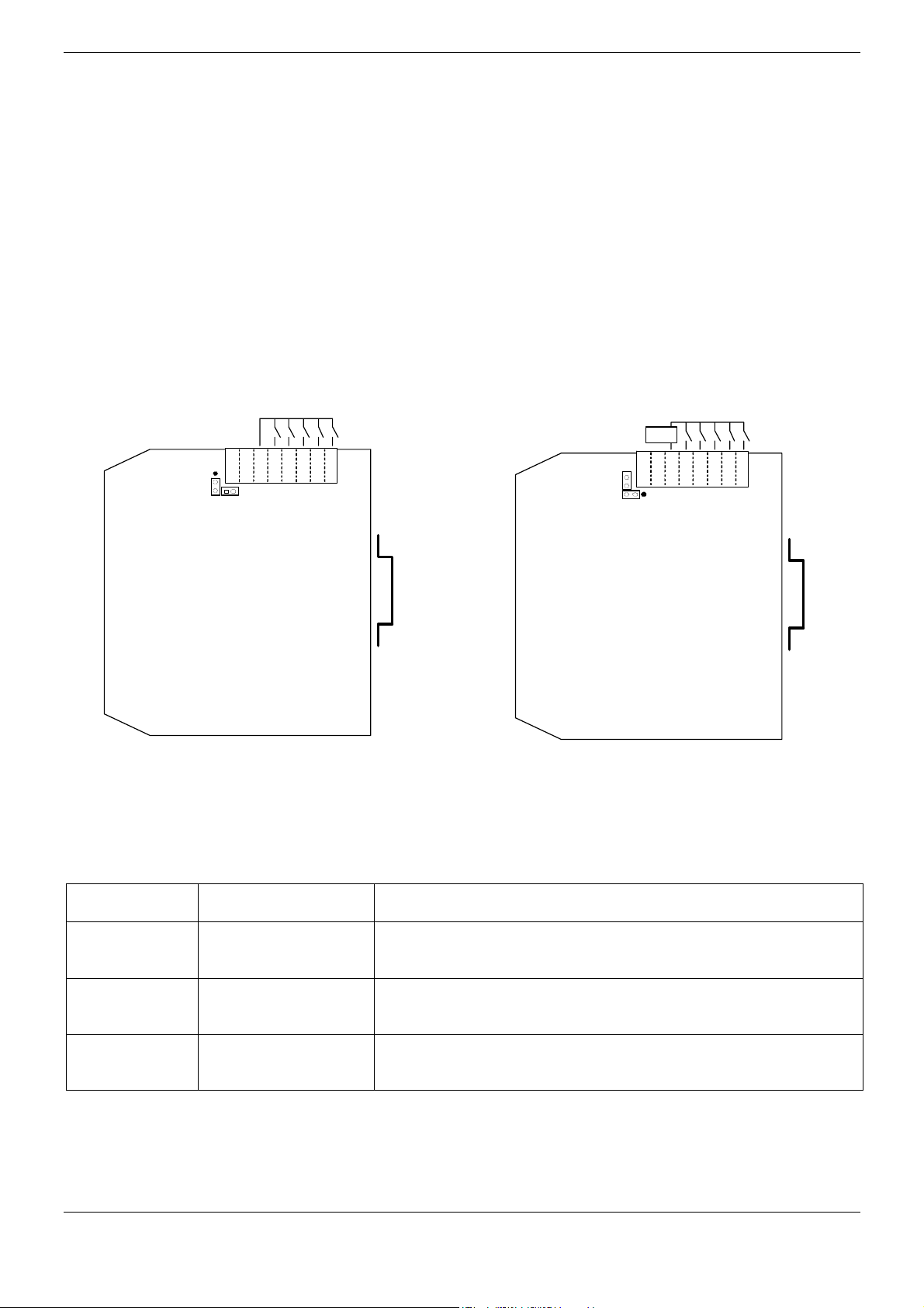
3.1 Input voltage
All inputs are provided with photo couplers. To activate the inputs you can either use the internal voltage supply or
use an external supply. When using an external supply you must first change the internal jumper J2 in accordance
with the drawing and table below.
Attention!
The printed circuit board consists of electrostatic sensitive components. While working with the printed circuit board
please use electrostatic protective measures to prevent any damage to the components. Do not touch the board or
any of the components!
Internally provided inputs, Externally provided inputs,
No galvanic isolation galvanic isolation inside counter
ca. 5 mA @ 12 V
ca. 10 mA @ 24 V
Ub = 12..24 V DC
.
.
n.
n.
Res
Com
In 4
In 3
In 2
In 1
Ub
.
.
n.
n.
Res
Co
In 4
In 3
In 2
In 1
J2
J2
Attention!
Terminal „C“ at the front side, near to the terminals of the supply voltage, can only be used with internal Power
Supply as an alternative connection to terminal „Com“. Terminal „C“ mustn’t be wired if external Power Supply is
used.
Inputs of several counter units can be connected in parallel as follows:
Power Supply Input power Attention
• Use only one power supply for all counter units!
• Do not connect terminal “C”. Terminals “In1..4” and “Res” are
internally connected to 0 V.
12..24V DC
Internal
J2 to down and right
12..24V AC
12..24V AC/DC
Internal
J2 to down and right
External 12..24V DC
J2 to up and left
• Do not connect multiple counter units in parallel!
• Use only one external power supply for all inputs!
FEIG ELECTRONIC GmbH 12/11 13
Page 14

Operating Instructions VEK CN1-1
3.2 Wiring of Relays Outputs
By switching of inductive loads additional external noise suppression is needed.
The output relay is constructed for small and large loads. Look for maximum and minimum load in the technical
data.
Attention!
If the relay contacts are loaded once for more than 100 mA, the gold gladding of the relay contacts becomes
destroyed. The use in systems with small loads isn´t possible anymore!
4 Technical Data
Dimensions 3 ” (79 mm) x ¾ ” (22.5 mm) x 3.5 ” (90 mm) (H x W x L without plug)
Protection Class IP 40
Power Supply 12 V to 24 V AC/DC ±10%
Power Consumption max. 2 W
Operating Temperature -20 °C to +70 °C
Storage Temperature -40 °C to +70 °C
Humidity max. 95 %, non-condensing
Counting range Total –999 to 9.999
0 .. 9.999.999 for each counting input
Inputs Photo Coupler, common anode (minus-switching)
4 Inputs
1 Reset input
Minimum input time 50 ms
Input current ca. 5 mA at 12 V
ca. 10 mA at 24 V
Relay output Form C
max. Current Rating AC: 250 V / 5 A / 125 VA
DC: 220 V / 2 A / 60 W
min. Current Rating 0,25 W / 10 mV / 1 mA
Fuse none, must be external
Suppressors none, if needed external
Air- and Leakage Path:
between Power Supply/Electronics and pins 5.5 mm
between pins 3.0 mm
between Power Supply/Electronics and pins 0.5 mm
Connection Screw Terminal (Power Supply, Relay output)
Block Terminals (Input)
CE-Standards EN 50082-2, Feb. 1996
EN 50081-1, March 1993
14 12/11 FEIG ELECTRONIC GmbH
Page 15

Operating Instructions VEK CN1-1
5 Safety instructions and Warnings
• The device may only for the purpose intended by the manufacturer.
• These operating instructions have to be handed out to every user and kept in an easily accessible
place.
• Unacceptable changes as well as the use of spare parts and special features which are not sold or
recommended by the manufacturer may cause fire, electric shocks and injuries. Such measures do
therefore lead to nonliability of the manufacturer and a lapse of all warranty claims.
• The appliance is subject to the manufacturer’s guarantee regulations in the version valid at the time
of purchase. We cannot be held liable for improper or faulty manual or automatic adjustment of
parameters resp. improper use of the appliance.
• Repair work may only be carried out by the manufacturer.
• Installation, initiation, maintenance, measuring and adjustment of the counting unit should only be
carried out by electricians with a good knowledge of the rules for prevention of accidents.
• When handling appliances that get in contact with electricity, the valid VDE-regulations have to be
observed. In particular, these are: VDE 0100, VDE 0550/0551, VDE 0700, VDE 0711, VDE 0860,
VDE 0105 as well as the rules for the prevention of accidents and fire VBG4.
• Before opening the device be assure that power is turned off and re-measure if power is down.
• If an operation display goes out, this is not a proof that the appliance is disconnected from the mains
and idle.
• All labour that is carried out on the appliance as well as its installation has to conform to the national
as well as the local electric regulations.
• The user has to make sure that the appliance is installed and operated according to the technical
rules of the country of installation as well as other regional regulations. Cable dimensions,
protection, grounding, disconnection, insulation control and excess current protection should be
especially considered.
• The gold gladded relay contacts will be destroyed for switching currents higher than 100 mA. Relays
with such pre-stressed contacts can certainly switch only currents higher than 100 mA.
FEIG ELECTRONIC GmbH 12/11 15
Page 16
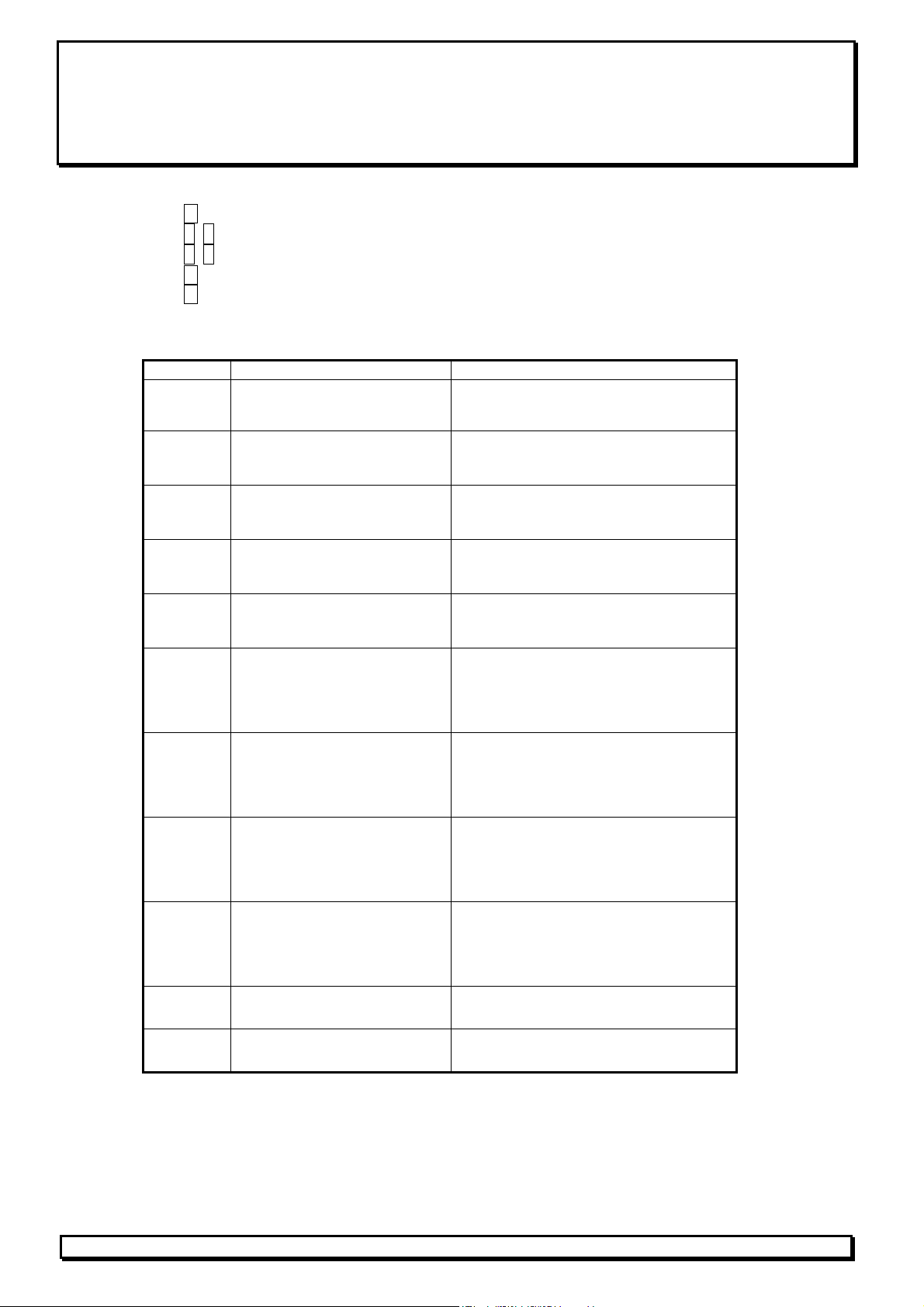
Start-up protocol - Digital Counter Unit VEK CN1-1
Location: ____________________________________________________
Date: ____________ Name: ________________________________
Hold M 2 s in normal operation → Display alternating SYS and program version (e.g. A03 )
Hold ∧, ∨ → change settings
Hold ∧, ∨ long → fast scroll
Hold M 2 s → save
Hold M short → next menu item
Hold two simultaneously → back to normal operation
Display
S oc
HYS
SkP~
SkP_
inP1
inP2
inP3
inP4
rEL
LoPo
Menu item Setting
Program Version
Threshold
0...9.999
Counter Hysteresis
1...250
Upper Counter Threshold
0...9.999
Lower Counter Threshold
0...-999
Input Function 1
Vers.: __________ (read only)
Value: __________
Value: __________
Value: __________
Value: __________
Add increment
Sub
rEs
no.F
Input Function 2
Add increment
Sub
rEs
no.F
Input Function 3
Add increment
Sub
rEs
no.F
Input Function 4
Add increment
Sub
rEs
no.F
Output Function
oc.on normally closed
Fr.on
Power Saving Mode
off off (Display on)
on
decrement
reset
no function
decrement
reset
no function
decrement
reset
no function
decrement
reset
no function
normally open
on (Display off)
FEIG ELECTRONIC GmbH * D-35781 Weilburg * Lange Str. 4 * Tel.: +496471/3109-0 * Fax: +496471/3109-99
 Loading...