

Page 1
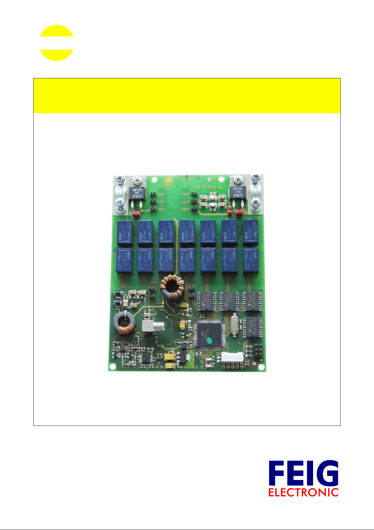
OBID i-scan
®
MONTAGE
INSTALLATION
ID ISC.DAT
Dynamic Antenna Tuner
(deutsch / english)
final
public (B)
2008-09-18
M40401-4de-ID-B.doc
Page 2
OBID i-scan
®
D E U T S C H
E N G L I S H
Montage ID ISC.DAT
deutsche Version ab Seite 3
english version from page 24
FEIG ELECTRONIC GmbH Seite 2 von 44 M40401-4de-ID-B.doc
Page 3

OBID i-scan
®
Montage ID ISC.DAT
Hinweis
© Copyright 2004-2008 by
FEIG ELECTRONIC GmbH
Lange Straße 4
D-35781 Weilburg-Waldhausen
Tel.: +49 6471 3109-0
http://www.feig.de
Alle früheren Ausgaben verlieren mit dieser Ausgabe ihre Gültigkeit.
Die Angaben in diesem Dokument können ohne vorherige Ankündigung geändert werden.
Weitergabe sowie Vervielfältigung dieses Dokuments, Verwertung und Mitteilung ihres Inhalts sind nicht
gestattet, soweit nicht ausdrücklich zugestanden. Zuwiderhandlung verpflichtet zu Schadenersatz. Alle
Rechte für den Fall der Patenterteilung oder Gebrauchsmuster-Eintragung vorbehalten.
Die Zusammenstellung der Informationen in diesem Dokument erfolgt nach bestem Wissen und Gewissen.
FEIG ELECTRONIC GmbH übernimmt keine Gewährleistung für die Richtigkeit und Vollständi gkeit der
Angaben in diesem Dokument. Insbesondere kann FEIG ELECTRONIC GmbH nicht für Folgeschäden auf
Grund fehlerhafter oder unvollständiger Angaben haftbar gemacht werden. Da sich Fehler, trotz aller
Bemühungen nie vollständig vermeiden lassen, sind wir für Hinweise jederzeit dankbar.
D E U T S C H
Die in diesem Dokument gemachten Installationsempfehlungen gehen von günstigsten
Rahmenbedingungen aus. FEIG ELECTRONIC GmbH übernimmt keine Gewähr für di e einwandfreie
Funktion in systemfremden Umgebungen.
FEIG ELECTRONIC GmbH übernimmt keine Gewährleistung dafür, dass die in diesem Dokument
enthaltenden Informationen frei von fremden Schutzrechten sind. FEIG ELECTRONIC GmbH erteilt mit
diesem Dokument keine Lizenzen auf eigene oder fremde Patente oder andere Schutzrechte .
®
OBID
und OBID i-scan® ist ein eingetragenes Warenzeichen der FEIG ELECTRONIC GmbH.
FEIG ELECTRONIC GmbH Seite 3 von 44 M40401-4de-ID-B.doc
Page 4

OBID i-scan
®
Montage ID ISC.DAT
Inhalt
1 Sicherheits- und Warnhinweise - vor Inbetriebnahme unbedingt lesen 5
2 Leistungsmerkmale des dynamischen Antennentuners ID ISC.DAT 6
D E U T S C H
3 Anschluss und Montage 7
3.1 Maße und Montage der Leiterplatte.............................................................................7
3.2 Anschlussbuchsen und Stiftleisten.............................................................................8
3.2.1 X1: Readeranschluss und Spannungsversorgung..........................................................9
3.2.2 X2: Boot Loader Interface ...............................................................................................9
3.2.3 X3: Ausgänge OUT1-3..................................................................................................10
3.2.4 X6, X7: Anschluss des Antennenleiters ........................................................................11
4 Bedien- und Anzeigeelemente 12
4.1 LEDs .............................................................................................................................12
4.2 Jumper JP1 und JP2: Einstellung der Güte..............................................................12
4.3 Jumper JP3: Einstellung Antennenschalter............................................................. 12
5 Inbetriebnahme 14
5.1 Voreinstellung der Abgleichkapazitäten...................................................................14
5.2 Einstellung der Güte ...................................................................................................19
5.3 Anschluss und Abgleich.............................................................................................20
5.3.1 Spannungsversorgung ..................................................................................................20
5.3.2 Abgleichen der Antenne................................................................................................21
5.4 Betrieb ohne Spannungsversorgung........................................................................ 21
6 Technische Daten 22
6.1 Zulassung (CE)............................................................................................................23
FEIG ELECTRONIC GmbH Seite 4 von 44 M40401-4de-ID-B.doc
Page 5

OBID i-scan
®
Montage ID ISC.DAT
1 Sicherheits- und Warnhinweise - vor Inbetriebnahme unbedingt lesen
• Das Gerät darf nur für den vom Hersteller vorgesehenen Zweck verwendet werden.
• Die Bedienungsanleitung ist zugriffsfähig aufzubewahren und jedem Benutzer auszuhändigen.
• Unzulässige Veränderungen und die Verwendung von Ersatzteilen und Zusatzeinrichtungen,
die nicht vom Hersteller des Gerätes verkauft oder empfohlen werden, können Brände,
elektrische Schläge und Verletzungen verursachen. Solche Maßnahmen führen daher zu
einem Ausschluss der Haftung und der Hersteller übernimmt keine Gewährleistung.
• Für das Gerät gelten die Gewährleistungsbestimmungen des Herstellers in der zum Zeitpunkt
des Kaufs gültigen Fassung. Für eine ungeeignete, falsche manuelle oder automatische
Einstellung von Parametern für ein Gerät bzw. ungeeignete Verwendung eines Gerätes wird
keine Haftung übernommen.
• Reparaturen dürfen nur vom Hersteller durchgeführt werden.
• Anschluss-, Inbetriebnahme-, Wartungs-, und sonstige Arbeiten am Gerät dürfen nur von
Elektrofachkräften mit einschlägiger Ausbildung erfolgen.
• Alle Arbeiten am Gerät und dessen Aufstellung müssen in Übereinstimmung mit den
nationalen elektrischen Bestimmungen und den örtlichen Vorschriften durchgeführt werden.
• Beim Arbeiten an dem Gerät müssen die jeweils gültigen Sicherheitsvorschriften beachtet
werden.
• Es ist darauf zu achten, dass verschiedene Teile des Gerätes heiß werden können.
D E U T S C H
• Vor Berührung der Platine ist stets die Spannungsversorgung abzuschalten und durch
Nachmessen sicherzustellen, dass das Gerät spannungslos ist. Das Verlöschen einer
Betriebsanzeige ist kein Indikator dafür, dass das Gerät vom Netz getrennt und spannungslos
ist.
Achtung! An dem Antennen-Tuner und dem Antennenleiter liegen Spannungen bis zu
1kV an.
• Besonderer Hinweis für Träger von Herzschrittmachern:
Obwohl dieses Gerät die zulässigen Grenzwerte für elektromagnetische Felder nicht überschreitet, sollten Sie einen Mindestabstand von 25 cm zwischen dem Gerät und Ihrem Herzschrittmacher einhalten und sich nicht für längere Zeit in unmittelbarer Nähe des Geräts bzw.
der Antenne aufhalten.
FEIG ELECTRONIC GmbH Seite 5 von 44 M40401-4de-ID-B.doc
Page 6
OBID i-scan
®
Montage ID ISC.DAT
2 Leistungsmerkmale des dynamischen Antennentuners ID ISC.DAT
Der dynamische Antennentuner ID ISC.DAT eignet sich zum automatischen Ab- und Nachgleichen
von RFID-Antennen mit einer Betriebsfrequenz von 13,56MHz. Die Messung der Parameter zum
Einstellen der Antenne erfolgt auf der Platine unter Betriebsbedingungen. Der Antennentuner ist
D E U T S C H
zusätzlich in der Lage, bis zu einer bestimmten Leistung (siehe 6 Technische Daten, Antennen-
schalter) den Antennenkreis über einen elektronischen Schalter aufzutrennen.
Die Ansteuerung des Antennentuners ID ISC.DAT und erfolgt über die HF-Verbindung. Der Anten-
1
nentuner funktioniert somit als sog. Funktionseinheit
.
Gemessene Parameter oder der Abgleichstatus können an den Host über die HF-Verbindung gesendet werden.
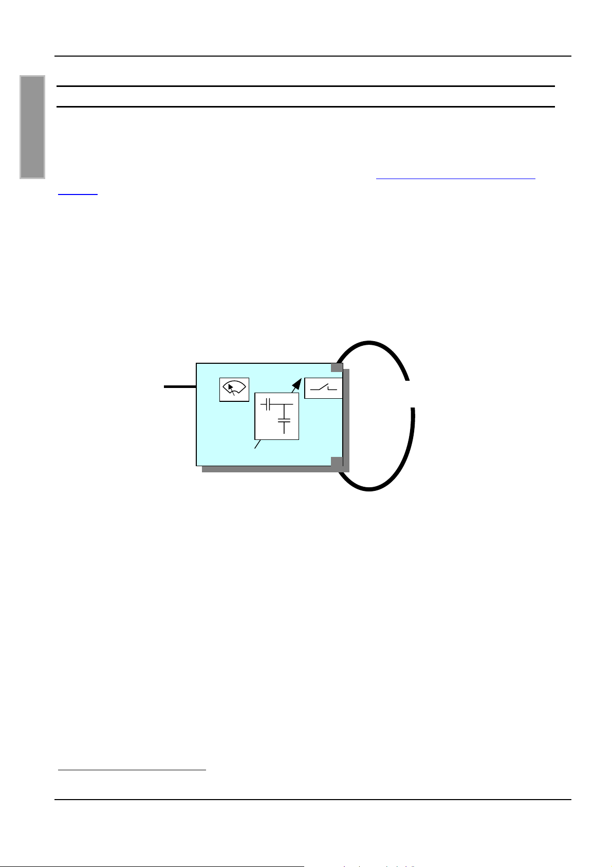
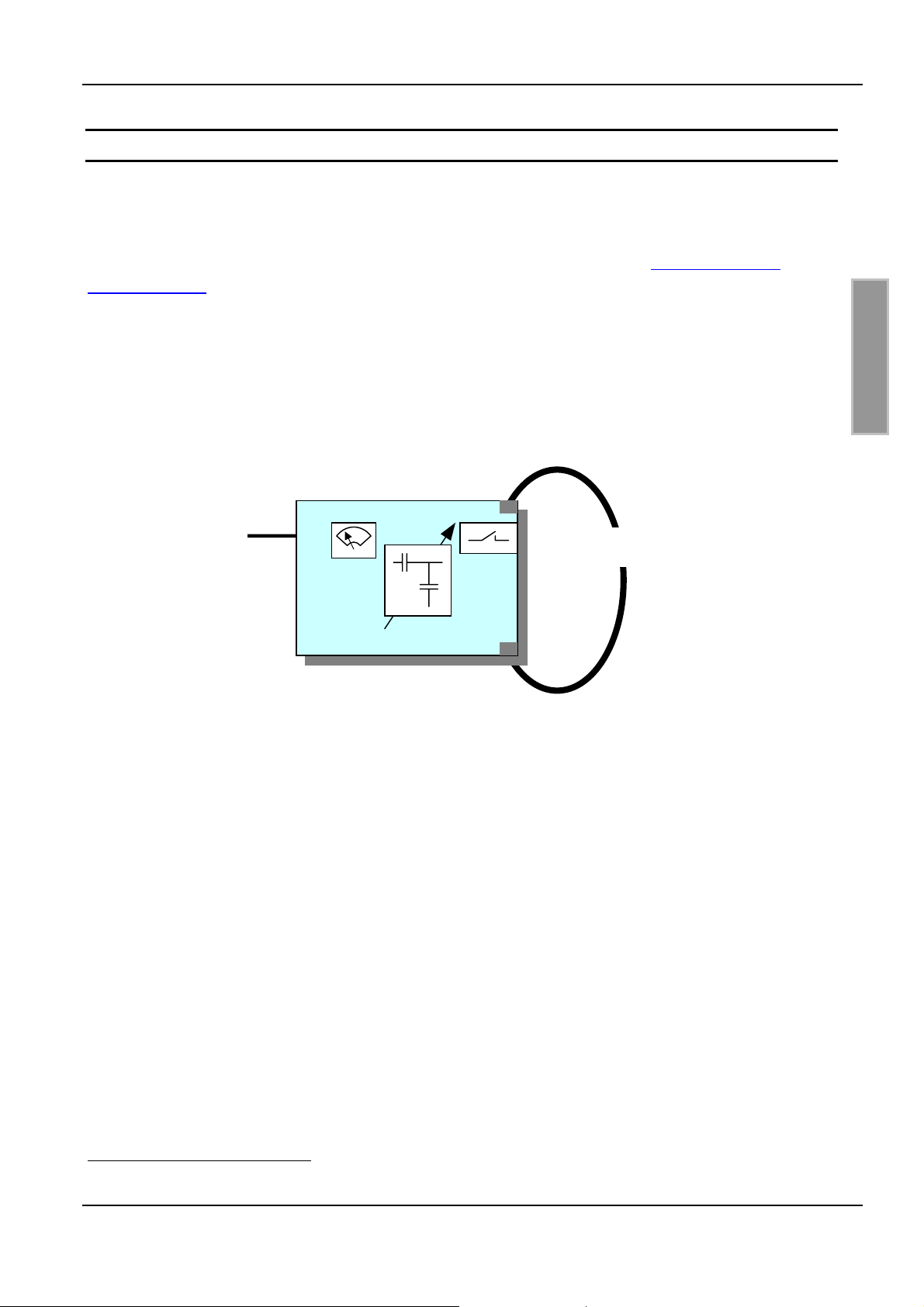
In Bild 1 sind die wichtigsten Komponenten des Antennentuners ID ISC.DAT mit Antennenschleife
in einem Blockschaltbild dargestellt.
ID ISC.DAT
X1
Antennenschleife
Bild 1: Blockschaltbild Antennentuner ID ISC.DAT
1
Funktionseinheit gemäß Handbuch Kommunikation FU: H30701-x-ID-B
FEIG ELECTRONIC GmbH Seite 6 von 44 M40401-4de-ID-B.doc
Page 7
OBID i-scan
®
Montage ID ISC.DAT
3 Anschluss und Montage
3.1 Maße und Montage der Leiterplatte
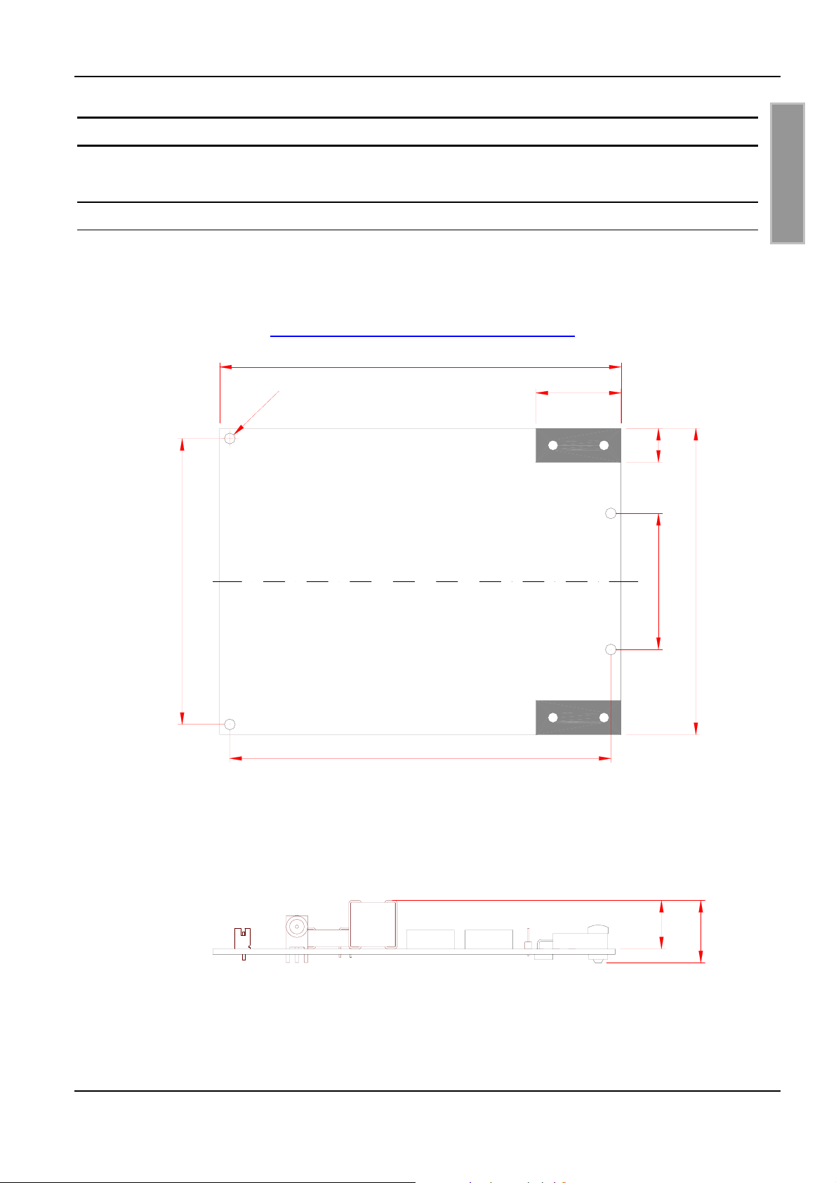
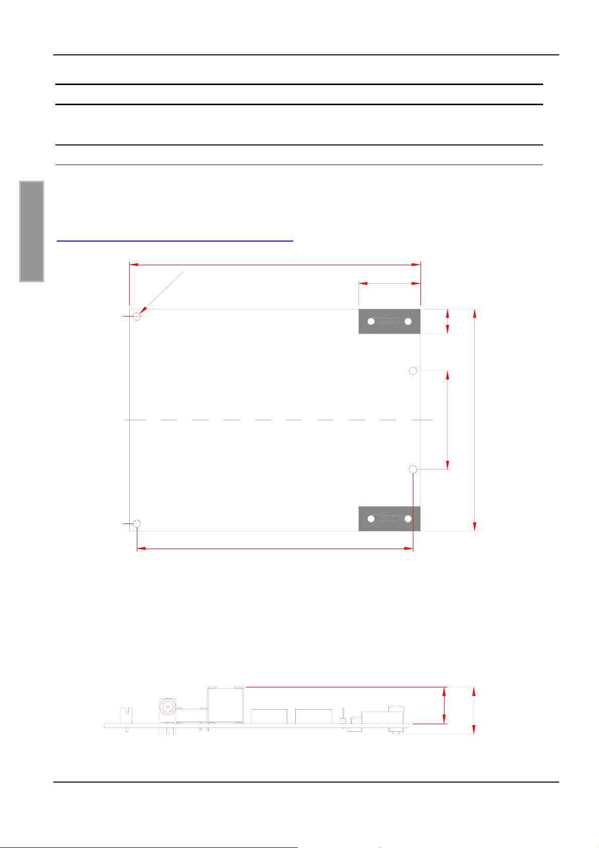
Der dynamische Antennentuner ist für die Montage in ein Gehäuse konzipiert. Zur Befestigung
befinden sich an den Rändern der Leiterplatte vier 3,2mm Bohrung (siehe Bild 2). Zur Befestigung
der Antennenschleife siehe 3.2.4 X6, X7: Anschluss des Antennenleiters.
118
D E U T S C H
84
2
,
3
x
4
112
Bild 2: Masse und Befestigungsbohrungen
25
1040
90
Die maximale Bauhöhe der Platine ist in Bild 3 dargestellt:
14,2
18,3
Bild 3: Maximale Bauhöhe
FEIG ELECTRONIC GmbH Seite 7 von 44 M40401-4de-ID-B.doc
Page 8
OBID i-scan
®
Montage ID ISC.DAT
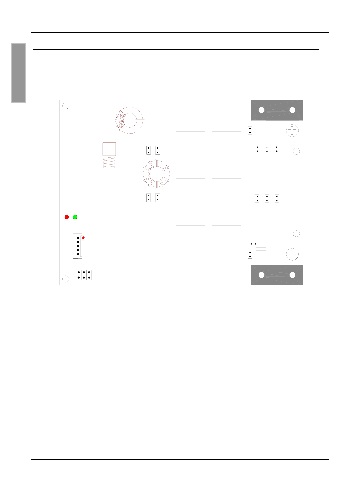
3.2 Anschlussbuchsen und Stiftleisten
In Bild 4 sind alle Anschlussbuchsen und –klemmen, Einstellelemente, Jumper und das Anzeigeteil
(LEDs) dargestellt.
D E U T S C H
LED
X2
X1
X6
JP14
JP12
JP21
JP23
JP25
JP26
JP24
JP22
JP11
JP13
JP3
JP2 JP1
X3
Bild 4: Anschlussbuchsen und –klemmen, Einstellelemente und LED
X7
FEIG ELECTRONIC GmbH Seite 8 von 44 M40401-4de-ID-B.doc
Page 9
OBID i-scan
®
Montage ID ISC.DAT
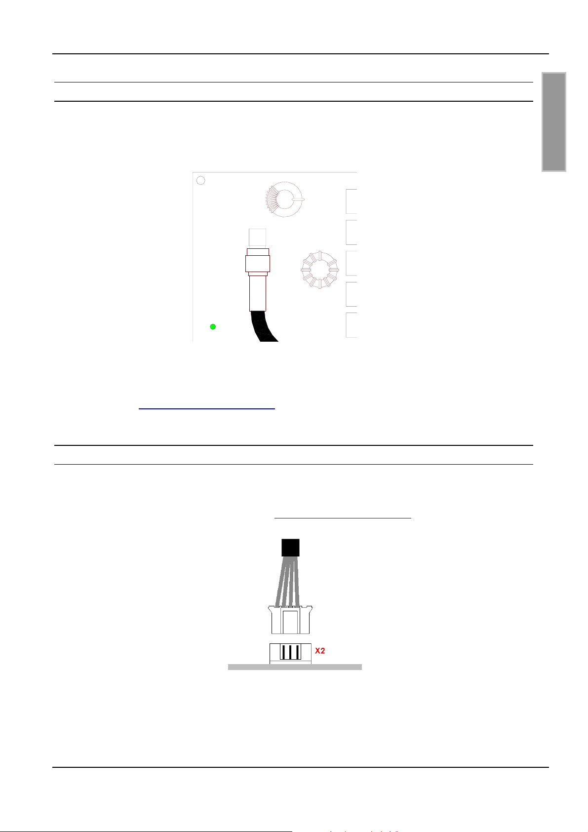
3.2.1 X1: Readeranschluss und Spannungsversorgung
Der Anschluss der HF-Leitung und der Spannungsversorgung erfolgt, wie in Bild 5 dargestellt, über
die SMA-Buchse X1. Der dynamische Antennentuner arbeitet mit einer Gleichspannung von
7 - 12V.
X1
D E U T S C H
Bild 5: Anschluss HF-Leitung und Spannungsversorgung
Die Spannungsversorgung von 7 –12 VDC liegt als Gleichspannungsoffset mit auf der HF-Leitung.
Siehe auch Kap. 5.3.1 Spannungsversorgung.
3.2.2 X2: Boot Loader Interface
Zum Durchführen eines Firmware Updates ist das Updatekabel ID CAB.RS-B auf die Stiftleiste X2
zu stecken (s. Bild 6). Die Spannungsversorgung erfolgt wie im Betrieb des Tuners über das Antennenkabel an Buchse X1. Siehe auch Kap. 5.3.1 Spannungsversorgung.
Bild 6: Anschluss Updatekabel
Die Durchführung des Firmware Updates ist in der entsprechenden Application Note ID ISC.DAT –
Firmware Update (N50801-xe-ID-B) genau beschrieben.
FEIG ELECTRONIC GmbH Seite 9 von 44 M40401-4de-ID-B.doc
Page 10
OBID i-scan
®
Montage ID ISC.DAT
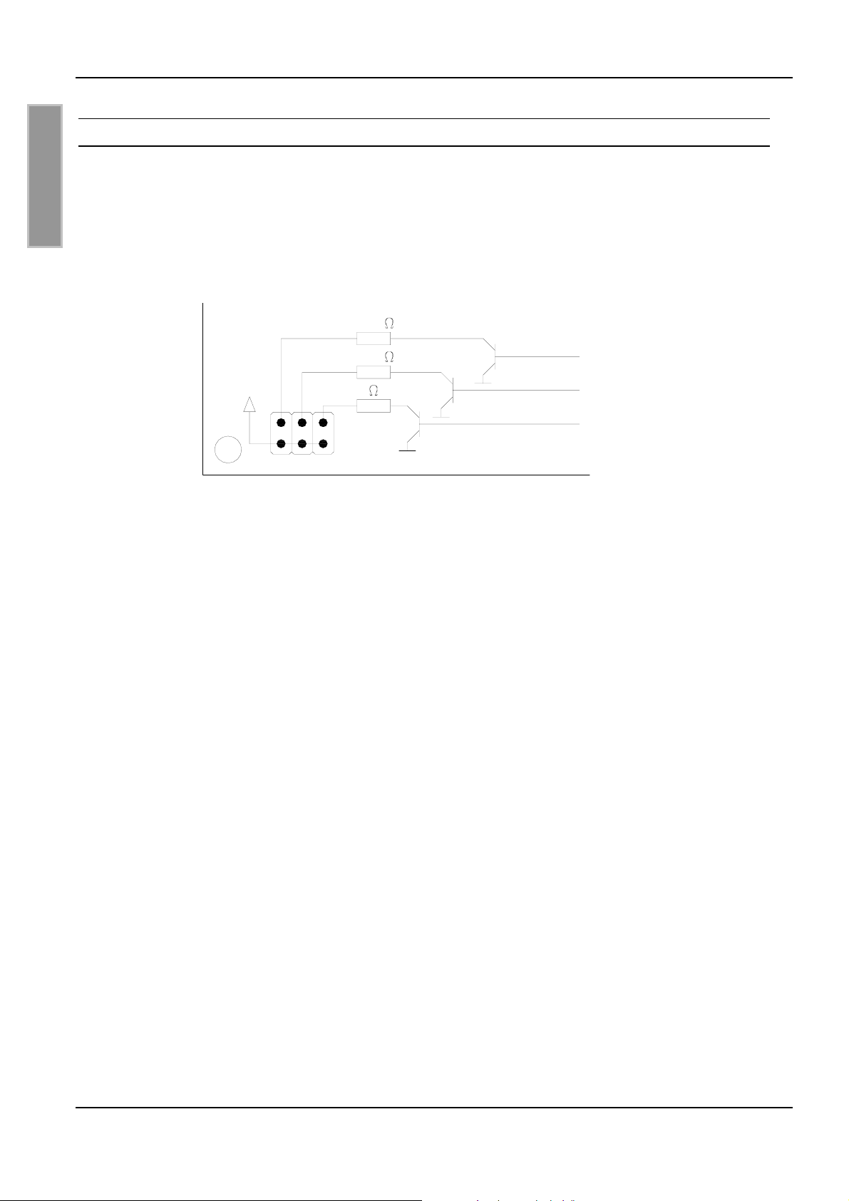
3.2.3 X3: Ausgänge OUT1-3
Die Ausgänge OUT1-3 können an der Stiftleiste X3 abgegriffen werden. Die Ausgänge können
jeweils bis zu einem Strom von I
= 15mA belastet werden (siehe Bild 7). Das Aktivieren aller drei
max
Ausgänge gleichzeitig ist nicht möglich.
D E U T S C H
330
OUT1
OUT2
OUT3
+5VDC
330
0
X3
Bild 7: Ausgänge OUT1-3
Hinweis:
Der Vorwiderstand von OUT3 beträgt 0Ω. Es ist darauf zu achten, dass auch hier ein Strom
von 15mA nicht überschritten wird!
FEIG ELECTRONIC GmbH Seite 10 von 44 M40401-4de-ID-B.doc
Page 11
OBID i-scan
®
Montage ID ISC.DAT
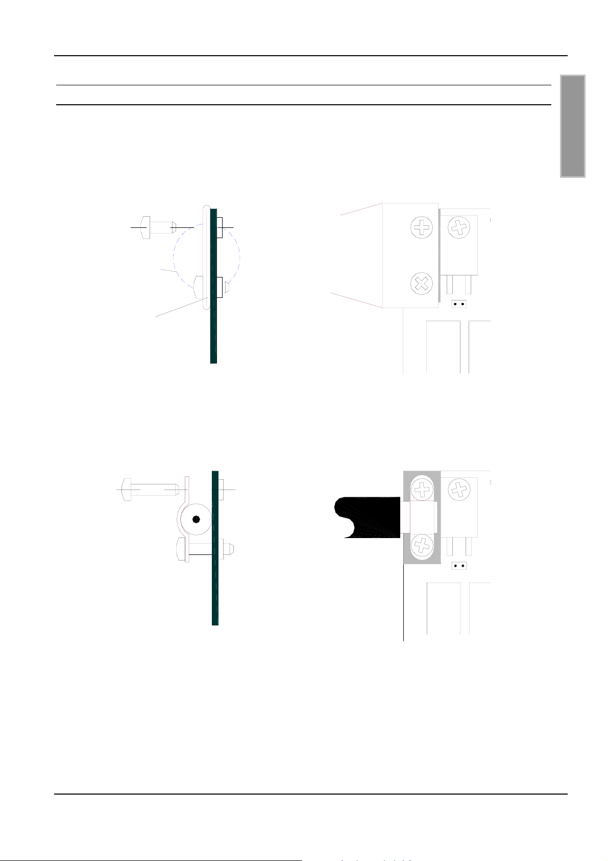
3.2.4 X6, X7: Anschluss des Antennenleiters
Der Anschluss des Antennenleiters an die Leiterplatte erfolgt über die Anschlussflächen X6 und
X7.
In Bild 8 ist die Montage eines Antennenleiter aus Kupferrohr (d
= 18mm; Enden zusammenge-
tube
presst) und in Bild 9 die einer Antenne aus Koaxialkabel (RG214) dargestellt.
M3x6
X6
Kontur Kupferrohr
Kupferrohr
(zusammengepresst)
Leiterplatte
Bild 8: Antennenanschluss (Kupferrohr)
D E U T S C H
JP1
M3x12
RG214
X6
X6
JP1
Leiterplatte
Bild 9: Antennenanschluss (Koaxialkabel RG214)
Hinweis:
Es ist darauf zu achten, dass ein guter elektrischer Kontakt zwischen Antennenleiter und
Anschlussflächen besteht.
FEIG ELECTRONIC GmbH Seite 11 von 44 M40401-4de-ID-B.doc
Page 12
OBID i-scan
®
Montage ID ISC.DAT
4 Bedien- und Anzeigeelemente
4.1 LEDs
D E U T S C H
Die grüne LED signalisiert durch blinken mit einer Frequenz von ca. 1 Hz den ordnungsgemäßen
Ablauf der internen Software.
Die rote LED signalisiert durch kurzes Aufblinken den Empfang eines Protokolls.
4.2 Jumper JP1 und JP2: Einstellung der Güte
Über die Jumper JP1 und JP2 werden die Widerstände zur Einstellung der Güte der Antenne eingestellt.
Zur Güteeinstellung siehe 5.2 Einstellung der Güte
4.3 Jumper JP3: Einstellung Antennenschalter
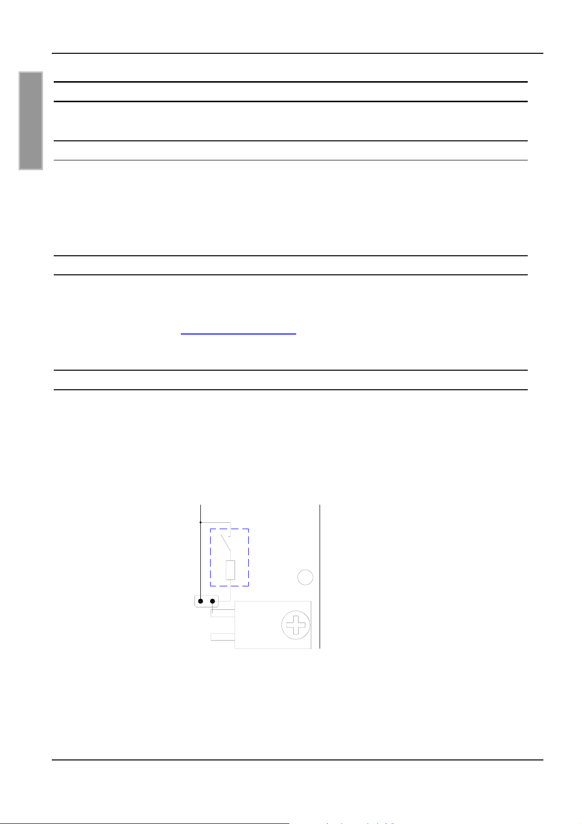
Mit dem Jumper JP3 wird der Schalter zum Auftrennen des Antennenschwingkreises gebrückt
(siehe ). Dies ist notwendig, wenn die Antenne ohne Spannungsversorgung betrieben werden soll
oder hohe Antennenströme
anschließend mit einem Hardware Reset (DC-Spannung aus und einschalten) abgeschlossen
werden.
auftreten. Siehe auch Tab. 1. Jede Änderung am Jumper JP3, muss
Schalter
JP3
Bild 10: JP3 Brücken des Antennenschalters
FEIG ELECTRONIC GmbH Seite 12 von 44 M40401-4de-ID-B.doc
Page 13
OBID i-scan
®
Montage ID ISC.DAT
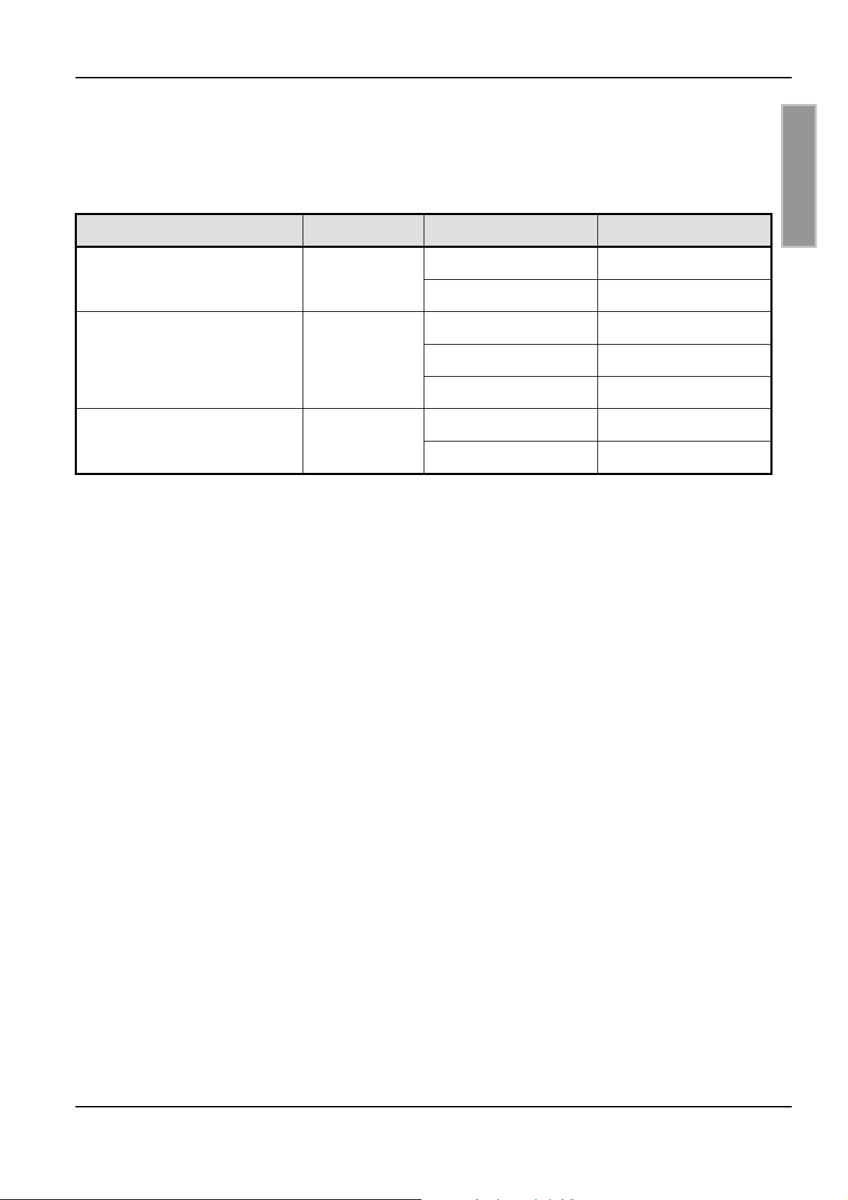
In folgender Tabelle ist die jeweils maximal zulässige HF-Leistung für verschiedene Güteeinstellungen und verschiedene Antennen aufgeführt, bis zu der der Antennenschalter betrieben werden
darf.
Tab. 1: maximale HF-Leistung im Dauerbetrieb
Antenne Induktivität Gütewiderstand max. HF-Leitung
ID ISCANT300300
(Single-Loop: 300mm x 300mm)
ID ISCANT800600
(Single-Loop: 800mm x 600mm)
ID ISCANT1400700
(8-Antenne: 1400mm x 700mm)
0,8µH
1,9µH
1,1µH
0Ω
3Ω
0Ω
3Ω
3Ω
0Ω
3Ω
3,5 W
7 W
6 W
6,5 W
8 W
3 W
8 W
Die maximal zulässige HF-Leistung erhöht sich, wenn die Leistung nicht dauerhaft anliegt (wie z.B.
bei der Verwendung eines Multiplexers).
D E U T S C H
FEIG ELECTRONIC GmbH Seite 13 von 44 M40401-4de-ID-B.doc
Page 14
OBID i-scan
®
Montage ID ISC.DAT
5 Inbetriebnahme
5.1 Voreinstellung der Abgleichkapazitäten
D E U T S C H
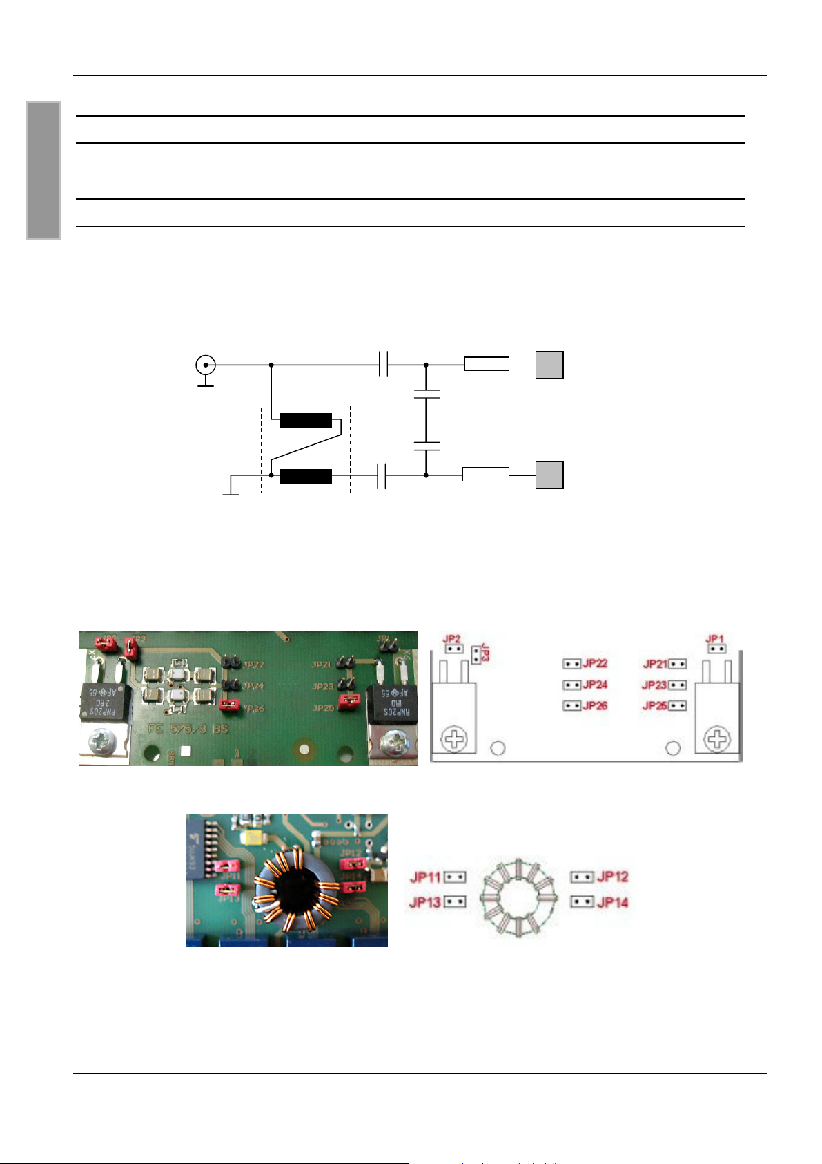
Der Antennenabgleich besteht aus einer Anpassschaltung aus Kondensatoren C1x (C11,C12) und
C2x (C21, C22) und einem Übertrager, der zur Symmetrierung des Antennenstroms als Balun verschaltet ist. Die Kondensatoren sind zur Symmetrierung in C11 und C12 (für C1x) und in C21 und
C22 (für C2x) aufgeteilt. Ein Ersatzschaltbild der Anpassschaltung mit Balun ist in Bild 11 darge-
stellt.
Bild 11: Ersatzschaltbild Anpassschaltung mit Balun
Mit Hilfe der Jumper können Kondensatoren zur Voreinstellungen der Anpasskapazitäten C1x und
C2x zugeschaltet werden. (Ab Hardware Version FE575/3). Siehe Bild 12 und Bild 13.
Bild 12 Zeigt die Position der Jumper JP21...JP26 (C2x) auf der Hardware Version FE575/3
Bild 13 Zeigt die Position der Jumpers JP11...JP14 (C1x) auf der Hardware Version FE575/3
FEIG ELECTRONIC GmbH Seite 14 von 44 M40401-4de-ID-B.doc
Page 15
OBID i-scan
®
Montage ID ISC.DAT
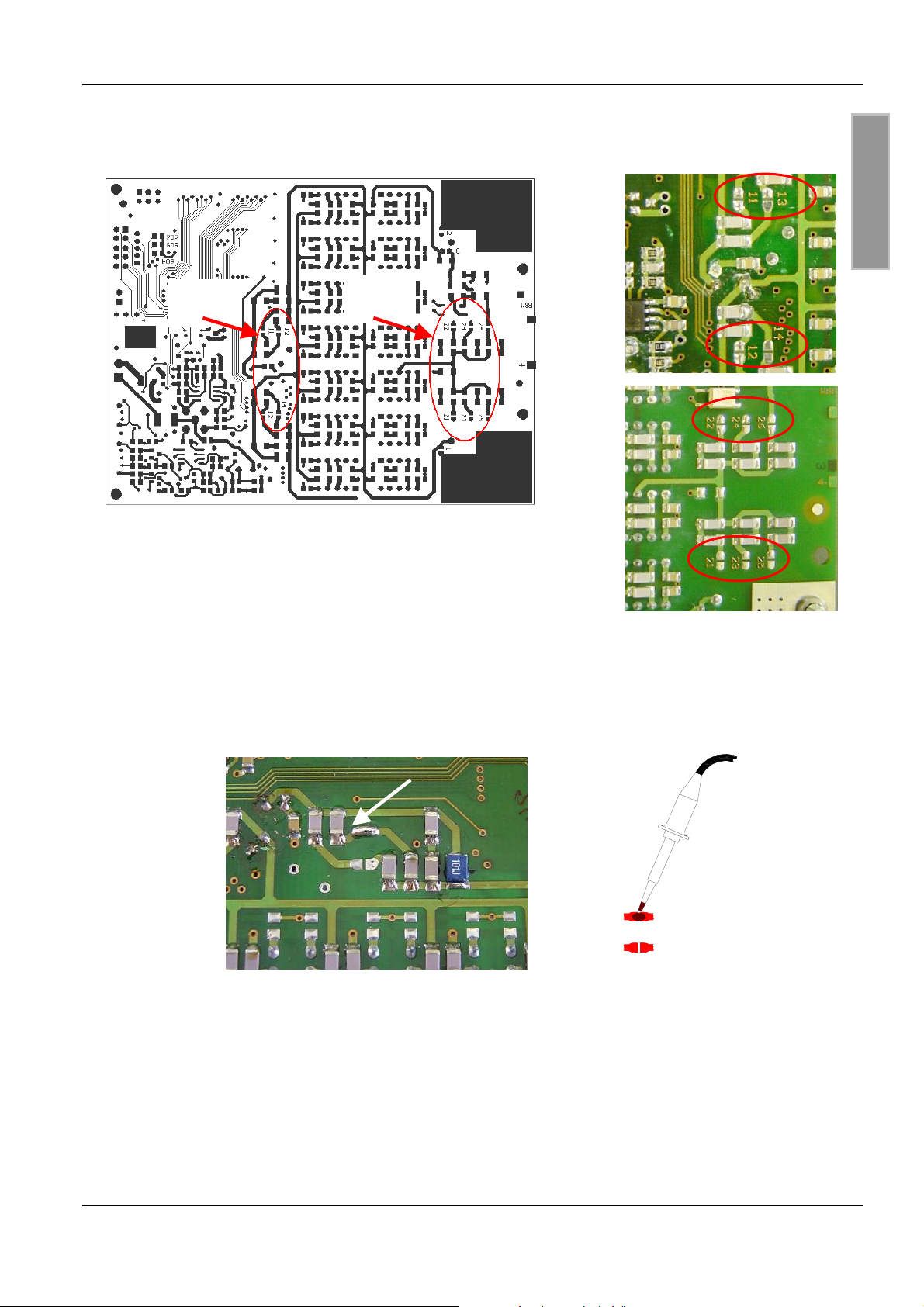
Alternativ zu den Jumpern können mit Hilfe der Lötbrücken 21..26 (C2x) und 11...14 (C1x) die Abgleichkapazitäten dazugeschaltet werden. (siehe Bild 14).
C1x:
(11-14)
C1x
C2x
C2x:
(21-26)
Bild 14: Position Lötbrücken der Anpasskondensatoren auf Unterseite
D E U T S C H
Bild 15 zeigt das Schließen der Lötbrücken mit dem Lötkolben und eine geschlossene Lötverbindung:
11
13
11
13
Bild 15: Schließen der Lötbrücke 11
FEIG ELECTRONIC GmbH Seite 15 von 44 M40401-4de-ID-B.doc
Page 16
OBID i-scan
®
Montage ID ISC.DAT
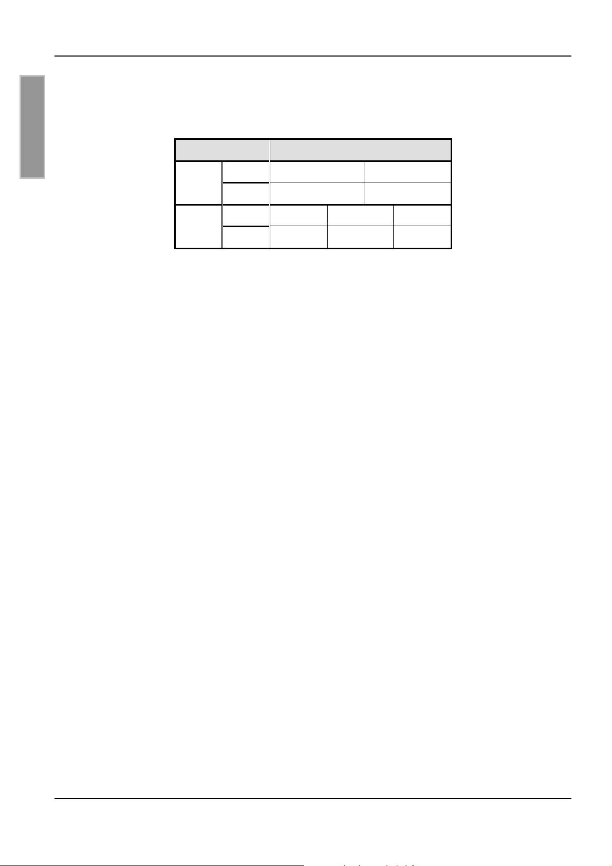
In Tab. 2 sind die Kapazitäten, die durch die entsprechenden Jumper bzw. Lötbrücken zugeschaltet werden, zusammengefasst:
Tab. 2: Jumper JP11-26
Kapazität Jumper / Lötbrücken
D E U T S C H
C1x
C2x
C11 11: 17pF 13: 33pF
C12 12: 17pF 14: 33pF
C21 21: 165pF 23: 82pF 25: 41pF
C22 22: 165pF 24: 82pF 26: 41pF
Hinweis:
Aufgrund der Symmetrie müssen die Werte C11 und C12, bzw. C21 und C22 immer gleich
groß sein. D.h. für C11 und C12, dass die Lötbrücken 11 und 12 bzw. 13 und 14 immer beide
verbunden oder offen sein müssen. Das gleiche gilt entsprechend für C21 und C22.
FEIG ELECTRONIC GmbH Seite 16 von 44 M40401-4de-ID-B.doc
Page 17
OBID i-scan
®
Montage ID ISC.DAT
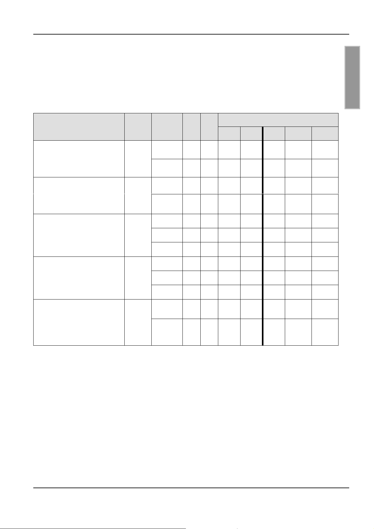
Der Wert der Voreinstellung hängt von der Induktivität und der Güte der abzugleichenden Antenne
ab. In Tab. 3 sind die Voreinstellungen für geläufige Antennen aufgelistet. Q gibt den Gütefaktor
bei dem jeweils gewählten Widerstandswert R1 und R2 an. C1 und C2 gibt die Werte an, die nach
einem erfolgreichen Abgleichvorgang mit dem ISOStart Kommando „Get antenna values“ ausgelesen wurden.
Feig- Standardantennen
ID ISCANT300300
(Single-Loop: 300mm x 300mm)
Aluminiumband 20mmx 1,5mm
ID ISCANT800600-DA
(Single-Loop: 800mm x 600mm)
18mm Kupferrohr
ID ISCANT1300680-A
(8-Antenne: 1300mm x 680mm)
10mm Aluminiumrohr Vollmaterial
ID ISCANT1400760-A/B/C
(8-Antenne: 1400mm x 700mm)
18mm Kupferorhr
Tab. 3: Voreinstellung der Kapazitäten
Jumper / Lötbrücken (geschlossen)
11/12 13/14 21/22 23/24 25/26
z z
L / µH
0,8
1,9
1,2
Q
(R1,R2)
56 (0Ω)
10 (3Ω)
50 (0Ω)
21 (3Ω)
57 (0Ω)
33 (1Ω)
16 (3Ω)
56 (0Ω)
33 (1Ω)
C1 C2
66 55
43 76
26 50
66 36
47 91
70 82
38 64
46 86
74 79
1,1
15 (3Ω)
46 60
z z z
D E U T S C H
z z
z z z
z
z
z
z
z z
z z
ID ISCANT1400760SLA/SLB
(Single Loops: 1400mm x 700mm)
18mm Kupferrohr
2,2
42 (0Ω)
23 (3Ω)
39 82
59 77
FEIG ELECTRONIC GmbH Seite 17 von 44 M40401-4de-ID-B.doc
Page 18
OBID i-scan
®
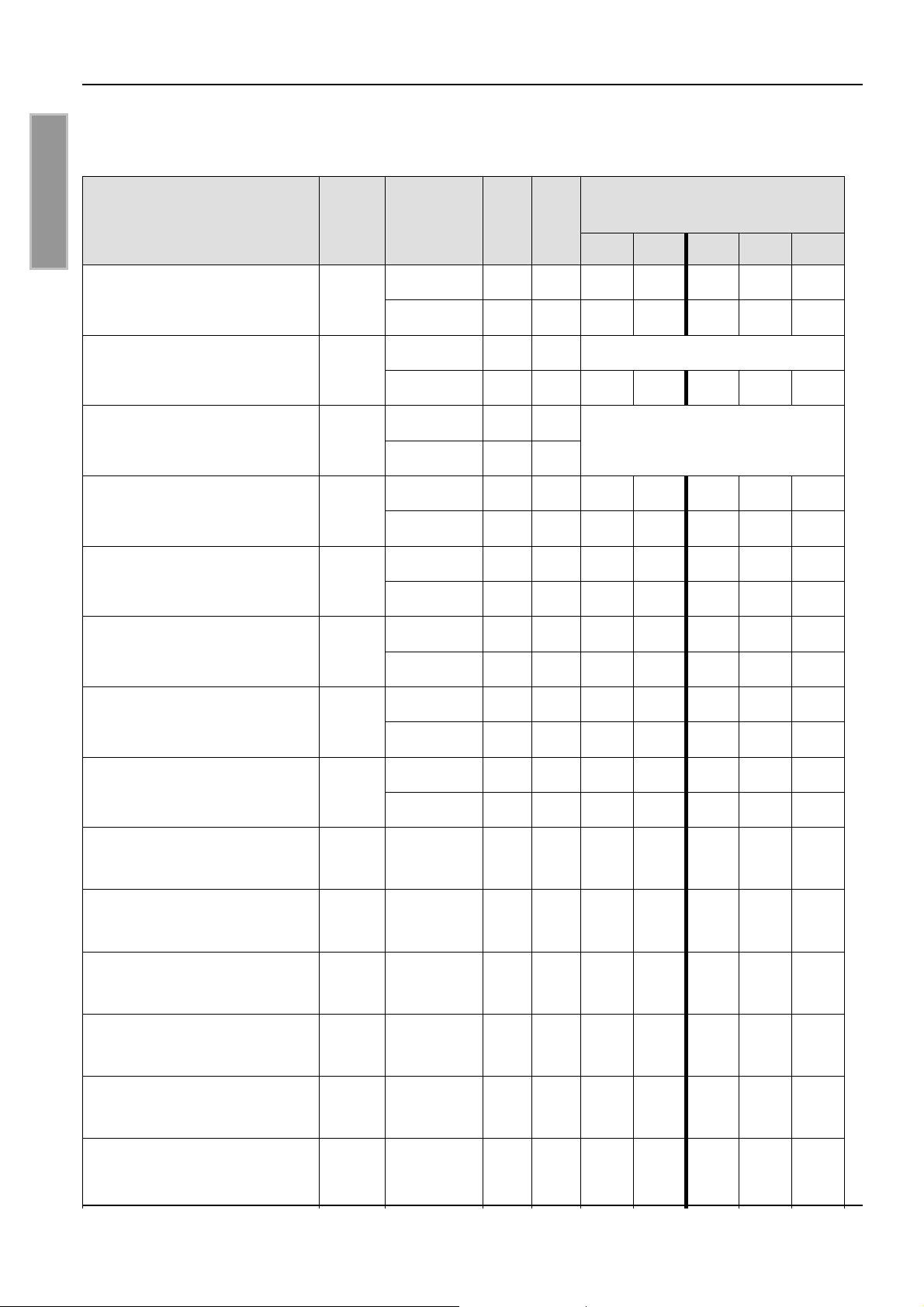
Weitere Beispiele:
Antenne
L / µH
Montage ID ISC.DAT
Jumper / Lötbrücken
Q (R1,R2) C1 C2
(geschlossen)
D E U T S C H
Kupferrohrantenne (∅ 18mm)
Single-Loop 1200mm x 650m
Koaxantenne (RG213)
Single-Loop ∅ 250mm
Kupferklebeband 25mm
Single-Loop 250 x 250mm
Kupferklebeband 25mm
Single-Loop 300 x 300mm
Kupferklebeband 25mm
Single-Loop 400 x 250mm
Kupferklebeband 25mm
Single-Loop 500 x 500mm
2,5
0,5
0,5
0,66
0,75
1,36
42 (0Ω)
23 (3Ω)
55 (0Ω)
8 (3Ω)
(0Ω)
(3Ω)
43 (0Ω)
9 (3Ω)
55 (0Ω)
10 (3Ω)
55 (0Ω)
17 (3Ω)
11/12 13/14 21/22 23/24 25/26
29 47
50 39
65 110 Abgleichbereich C2 zu niedrig
67 125
z z z z z
Abgleichbereich C1 und C2 zu
niedrig
82 56
84 76
68 70
64 85
40 84
25 60
z z z
z z z
z z
z z z
z z
z
Kupferklebeband 25mm
Single-Loop 600 x 400mm
Kupferklebeband 25mm
Single-Loop 600 x 600mm
Kupferklebeband 25mm
Single-Loop 1000x300mm
Kupferklebeband 25mm
Single-Loop 1060x400mm
Kupferklebeband 25mm
8-Antenne 2 x 600x340mm
Kupferklebeband 8mm
8-Antenne 2 x 400x400mm
Kupferklebeband 8mm
8-Antenne 2 x 500x500mm
Kupferklebeband 8mm
Single-Loop 250 x 250mm
1,36
1,7
1,8
2,4
0,7
0,5
0,68
0,8
53 (0Ω)
16 (3Ω)
34 (0Ω)
13 (3Ω)
33 (1Ω)
33 (1Ω)
21 (1Ω)
(1Ω)
(0Ω)
52 (0Ω)
42 83
28 58
50 76
83 65
48 70
44 29
53 94
113 92
70 70
68 52
z
z z
z
z
z
z
z z z
z z z
z
z z
FEIG ELECTRONIC GmbH Seite 18 von 44 M40401-4de-ID-B.doc
Page 19
OBID i-scan
®
Montage ID ISC.DAT
z z z
z
z
Kupferklebeband 8mm
Single-Loop 300 x 300mm
Kupferklebeband 8mm
Single-Loop 400 x 400mm
Kupferklebeband 8mm
Single-Loop 500 x 500mm
Kupferklebeband 8mm
Single-Loop 600 x 600mm
0,98
1,4
1,8
2,3
10 (3Ω)
46 (0Ω)
13 (3Ω)
46 (0Ω)
15 (3Ω)
44 (0Ω)
19 (3Ω)
38 (0Ω)
20 (3Ω)
64 68
66 70
74 41
48 74
32 51
40 67
76 55
40 83
64 74
z z
z z
5.2 Einstellung der Güte
Die Einstellung der Güte erfolgt über die Jumper JP1 und JP2. Durch Setzen der Jumper werden
die parallel dazu bestückten Widerstände gebrückt.
D E U T S C H
z
z
In Tab. 4 sind die möglichen Widerstandseinstellungen aufgelistet.
Tab. 4: Gütewiderstand
Jumper R1+R2
JP1 und JP2 geschlossen
JP1 offen, JP2 geschlossen
JP1 geschlossen, JP2 offen
JP1 und JP2 offen
0 Ω
1 Ω
2 Ω
3 Ω
FEIG ELECTRONIC GmbH Seite 19 von 44 M40401-4de-ID-B.doc
Page 20
OBID i-scan
®
Montage ID ISC.DAT
5.3 Anschluss und Abgleich
5.3.1 Spannungsversorgung
D E U T S C H
Für den Betrieb und den Abgleichvorgang ist eine Spannungsversorgung über die HF-Leitung erforderlich. Die Spannungsversorgung kann über verschiedene Möglichkeiten in die HF-Leitung
eingeschleift werden:
1. Multiplexer
Wird die Antenne an einem FEIG-Multiplexer ID ISC.ANT.MUX betrieben, kann dieser so konfiguriert werden, dass bis zu zwei Antennentuner ID ISC.DAT gleichzeitig über die HF-Verbindung mit
Spannung versorgt werden können (siehe Montageanleitung ID ISC.ANT.MUX
Tuner wird dann direkt an einen Ausgang des Multiplexers angeschlossen.
2
). Der Antennen-
2. Power-Splitter
Der FEIG-Power-Splitter ID ISC.ANT.PS-B kann so konfiguriert werden, dass er eine oder zwei
angeschlossene Antennentuner ID ISC.DAT mit Spannung versorgen kann (siehe Montageanlei-
3
tung ID ISC.ANT.PS-B
).
3. Reader mit Gleichspannungsoffset
Verfügt der angeschlossene Reader über einen Gleichspannungsoffset von 7-12V (Stromaufnahme 150mA, siehe Montageanleitung Reader LR2000,LRM2000,MR200) kann der Antennentuner
ID ISC.DAT direkt an den Reader angeschlossen werden.
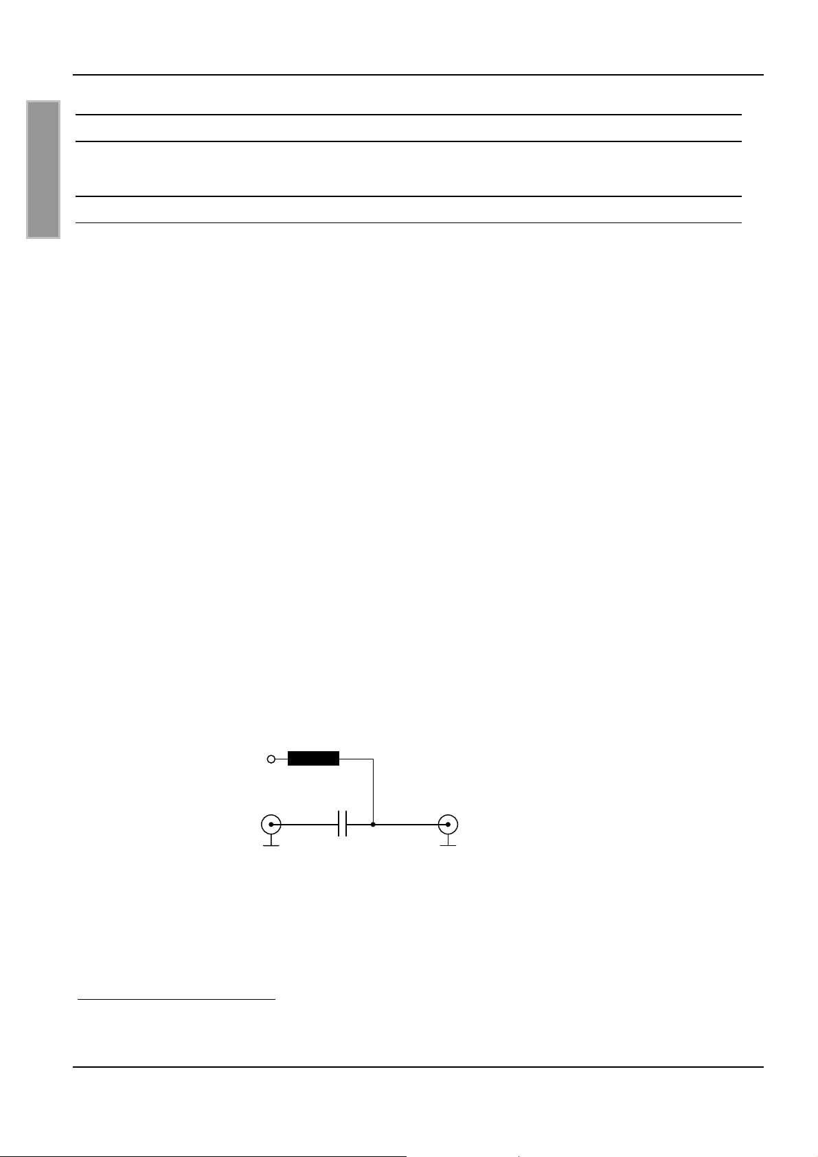
Sind keine der oben angeführten Möglichkeiten vorhanden, ist die Einspeisung der Gleichspannung auf das HF-Kabel gemäß Bild 16 auszuführen.
7-12V
DC
L: 10uH Epcos SIMID03 (B82432-A1103-K)
C: 100nF
Bild 16: Einspeisung Spannungsversorgung
2
Montageanleitung Antenna Multiplexer M30201-xde-ID-B
3
Montageanleitung Power-Splitter M40402-xde-ID-B
FEIG ELECTRONIC GmbH Seite 20 von 44 M40401-4de-ID-B.doc
Page 21
OBID i-scan
®
Montage ID ISC.DAT
5.3.2 Abgleichen der Antenne
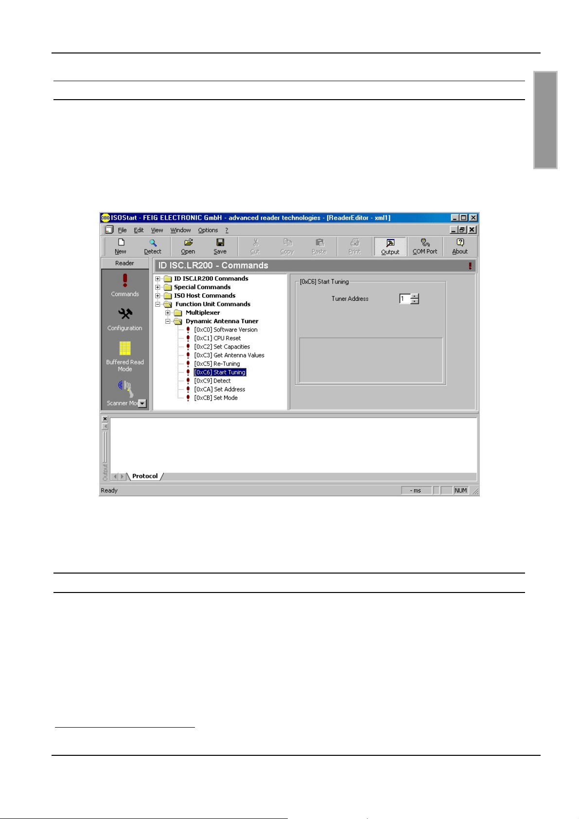
Der Antennentuner ID ISC.DAT wird über Protokolle4 vom Reader bzw. vom Host gesteuert. Die
Protokolle sind im Demoprogramm ISOStart (ab V 06.07) eingebunden (siehe Bild 17).
Beim ersten Abgleichen wird ein „Start Antenna Tuning“ durchgeführt. Ein Nachgleichen kann
durch ein „Re-Tuning“ eingeleitet werden. Bei komplexeren Antennenkonfigurationen sind den
Antennentunern zunächst einzeln Adressen über „Set Address“ zuzuordnen. Die ab Werk eingestellte Standardadresse ist 01.
D E U T S C H
Bild 17: ISOStart (ab V06.07): Function Unit Commands ⇒ Dynamic Antenna Tuner
Für das Tunen von Antennensystemen steht auch die Software „DATuningTool.exe“ zur
Verfügung.
5.4 Betrieb ohne Spannungsversorgung
Der Betrieb einer abgeglichenen Antenne ist auch ohne Spannungsversorgung möglich. Dabei
muss der Antennenschalter durch stecken von Jumper JP3 überbrückt sein.
Hinweis:
Einstellungen oder Parameterabfragen des Antennentuners ID ISC.DAT sind nur mit Span-
nungsversorgung durchführbar.
4
siehe Handbuch Kommunikation FU: H30701-xd-ID-B.doc
FEIG ELECTRONIC GmbH Seite 21 von 44 M40401-4de-ID-B.doc
Page 22

OBID i-scan
®
6 Technische Daten
Mechanische Daten
Montage ID ISC.DAT
D E U T S C H
• Abmessungen ( B x H x T )
• Gewicht
Elektrische Daten
• Spannungsversorgung
• Stromaufnahme
• Betriebsfrequenz
• max. zul. Sendeleistung
• Antennenanschluss
• Antennenschalter
• HF- Anschluss (Antenne)
118 mm x 90 mm x 19 mm
ca. 100 g
7 - 12 V DC
max. 150 mA (DC)
13,56 MHz
10 W**
Kabelklemmen d = 2 – 9mm
elektronischer Schalter **
(max. Antennenstrom beachten!)
SMA Buchse (50 Ω) *
• Ansteuerung
• Ausgänge
• Signalgeber
• Schnittstelle
Antennenparameter
• Trägerfrequenz
• Impedanz
• Abgleichbereich Induktivität
• Güte
* Maximales Anzugsdrehmoment: 0,45Nm
** Siehe Tabelle
Tab.1
Reader: Kommunikation über RF-Verbindung
3 x Open Collector: 5 V DC/ max. 15 mA
1 x „RUN“-LED (grün) , 1x „Protokoll“ -LED (rot)
RS232 TTL (für Firmware Update)
13,56MHz
50Ω
0,7 – 2,5µH
10 – 50
FEIG ELECTRONIC GmbH Seite 22 von 44 M40401-4de-ID-B.doc
Page 23

OBID i-scan
®
Umgebungsbedingungen
• Temperaturbereich
– Betrieb
– Lagerung
Montage ID ISC.DAT
-25°C bis +75°C
-40°C bis +85°C
D E U T S C H
• EMV
• Vibration
• Schock
EN61000-6-3
EN61000-6-2
EN60068-2-6
10 Hz bis 150 Hz : 0,075 mm / 1 g
EN60068-2-27
Beschleunigung : 30 g
6.1 Zulassung (CE)
Das Gerät entspricht bei bestimmungsgemäßer Verwendung den Anforderungen der EU-Richtline
89/336/EEC (Electromagnetic Compatibility (EMC).
Electromagnetic compatibility (EMC) –
Generic emission standard;
Part 6-3: Generic standards – Emission standard for residential,
commercial and light industry
Electromagnetic compatibility (EMC) –
Part 6-2: Generic standards – Immunity of industrial environments
EN 61000-6-3:2001
EN 61000-6-2:2001
FEIG ELECTRONIC GmbH Seite 23 von 44 M40401-4de-ID-B.doc
Page 24

OBID i-scan
®
Installation ID ISC.DAT
Note
© Copyright 2004-2008 by
FEIG ELECTRONIC GmbH
Lange Strasse 4
D-35781 Weilburg-Waldhausen
Tel.: +49 6471 3109-0
http://www.feig.de
With the edition of this document, all previous editions become void. Indications made in this manual may be
changed without previous notice.
Copying of this document, and giving it to others and the use or communication of the contents thereof are
forbidden without express authority. Offenders are liable to the payment of damages. All rights are reserved
E N G L I S H
in the event of the grant of a patent or the registration of a utility model or design.
Composition of the information in this manual has been done to the best of our knowledge.
FEIG ELECTRONIC GmbH does not guarantee the correctness and completeness of the details given in this
manual and may not be held liable for damages ensuing from incorrect or incomplete information. Since,
despite all our efforts, errors may not be completely avoided, we are always grateful for your useful tips.
The installation instructions given in this manual are based on advantageous boundary conditions.
FEIG ELECTRONIC GmbH does not give any guarantee promise for perfect function in cross environments.
FEIG ELECTRONIC GmbH assumes no responsibility for the use of any information contained in this
manual and makes no representation that they free of patent infringement. FEIG ELECTRONIC GmbH does
not convey any license under its patent rights nor the rights of others.
OBID® and OBID i-scan® are registered trademarks of FEIG ELECTRONIC GmbH.
FEIG ELECTRONIC GmbH Page 24 of 44 M40401-4de-ID-B.doc
Page 25

OBID i-scan
®
Installation ID ISC.DAT
Contents
1 Safety Instructions / Warning - Read before start-up ! 26
2 Performance features of the dynamic antenna tuner ID ISC.DAT 27
3 Hookup and Installation 28
3.1 Dimensions and installation of the circuit board..................................................... 28
3.2 Connection jacks and connectors.............................................................................29
3.2.1 X1: Reader connection and supply voltage...................................................................30
3.2.2 X2: Boot Loader Interface .............................................................................................30
3.2.3 X3: Outputs OUT1-3......................................................................................................31
3.2.4 X6, X7: Connecting the antenna conductor...................................................................32
4 Operating and Display Elements 33
4.1 LEDs .............................................................................................................................33
4.2 Jumpers JP1 and JP2: Setting the Q.........................................................................33
4.3 Jumper JP3: Setting the antenna switch ..................................................................33
5Startup 35
5.1 Presetting the calibration capacitances....................................................................35
5.2 Setting the Q................................................................................................................40
E N G L I S H
5.3 Connecting and tuning ...............................................................................................41
5.3.1 Supply voltage...............................................................................................................41
5.3.2 Tuning the antenna .......................................................................................................42
5.4 Operating without power supply................................................................................42
6 Technical data 43
6.1 Approval (CE)...............................................................................................................44
FEIG ELECTRONIC GmbH Page 25 of 44 M40401-4de-ID-B.doc
Page 26

OBID i-scan
®
Installation ID ISC.DAT
1 Safety Instructions / Warning - Read before start-up !
• The device may only be used for the intended purpose designed by for the manufacturer.
• The operation manual should be conveniently kept available at all times for each user.
• Unauthorized changes and the use of spare parts and additional devices which have not been
sold or recommended by the manufacturer may cause fire, electric shocks or injuries. Such
unauthorized measures shall exclude any liability by the manufacturer.
• The liability-prescriptions of the manufacturer in the issue valid at the time of purchase are valid
for the device. The manufacturer shall not be held legally responsible for inaccuracies, errors,
or omissions in the manual or automatically set parameters for a device or for an incorrect
E N G L I S H
application of a device.
• Repairs may only be executed by the manufacturer.
• Installation, operation, and maintenance procedures should only be carried out by qualified
personnel.
• Use of the device and its installation must be in accordance with national legal requirements
and local electrical codes .
• When working on devices the valid safety regulations must be observed.
• Please observe that some parts of the device may heat severely.
• Before touching the device, the power supply must always be interrupted. Make sure that the
device is without voltage by measuring. The fading of an operation control (LED) is no
indicator for an interrupted power supply or the device being out of voltage!
CAUTION! The Antenna-Tuner and the Antenna conductor carry voltages up to
1000V.
• Special advice for carriers of cardiac pacemakers:
Although this device doesn't exceed the valid limits for electromagnetic fields you should keep
a minimum distance of 25 cm between the device and your cardiac pacemaker and not stay in
an immediate proximity of the device respective the antenna for some time.
FEIG ELECTRONIC GmbH Page 26 of 44 M40401-4de-ID-B.doc
Page 27
OBID i-scan
®
Installation ID ISC.DAT
2 Performance features of the dynamic antenna tuner ID ISC.DAT
The dynamic antenna tuner ID ISC.DAT is designed for automatic calibrating and tuning of RFID
antennas with an operating frequency of 13.56 MHz. The parameters for setting the antenna are
measured on the board under operating conditions. The antenna tuner is also able to disconnect
the antenna circuit through an electronic switch up to a certain power (see 6 Technical data,
Antenna Switch).
The ID ISC.DAT is driven over the HF line. The antenna tuner thus functions as a so-called
1
function unit
.
Measured parameters or the calibration status can be sent to the host over the HF line.
Fig. 1 shows the key components of the ID ISC.DAT antenna tuner with an antenna loop.
ID ISC.DAT
X1
Antenna loop
Fig. 1: Block diagram of ID ISC.DAT antenna tuner
E N G L I S H
1
Function unit according to Manual Communication FU: H30701-x-ID-B
FEIG ELECTRONIC GmbH Page 27 of 44 M40401-4de-ID-B.doc
Page 28
OBID i-scan
®
Installation ID ISC.DAT
3 Hookup and Installation
3.1 Dimensions and installation of the circuit board
The dynamic antenna tuner is designed for installation in an enclosure. Four 3.2mm mounting
holes are provided on the edges of the circuit board (see Fig. 2). To attach the antenna loop see
3.2.4 X6, X7: Connecting the antenna conductor.
118 (4.65)
E N G L I S H
)
3
1
.
0
(
2
,
3
x
4
25 (0.98)
10 (0.4)
112 (4.41)
Fig. 2: Dimensions in mm (inch) and mounting holes
The maximum installation height of the board is shown in Fig. 3:
40 (1.57)
14,2 (0.56)
90 (3.54)
18,3 (0.72)
Fig. 3: Maximum installation height in mm (inch)
FEIG ELECTRONIC GmbH Page 28 of 44 M40401-4de-ID-B.doc
Page 29
OBID i-scan
®
Installation ID ISC.DAT
3.2 Connection jacks and connectors
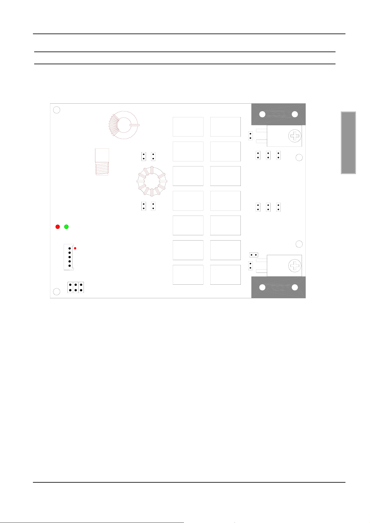
Fig. 4 shows all the connection jacks and terminals, setting devices and the display section (LED).
X6
X1
LED
X2
X3
JP14
JP12
JP11
JP13
Fig. 4: Connection jacks and terminals, setting devices and LED
JP3
JP2 JP1
JP21
JP23
JP25
JP26
JP24
JP22
X7
E N G L I S H
FEIG ELECTRONIC GmbH Page 29 of 44 M40401-4de-ID-B.doc
Page 30
OBID i-scan
®
Installation ID ISC.DAT
3.2.1 X1: Reader connection and supply voltage
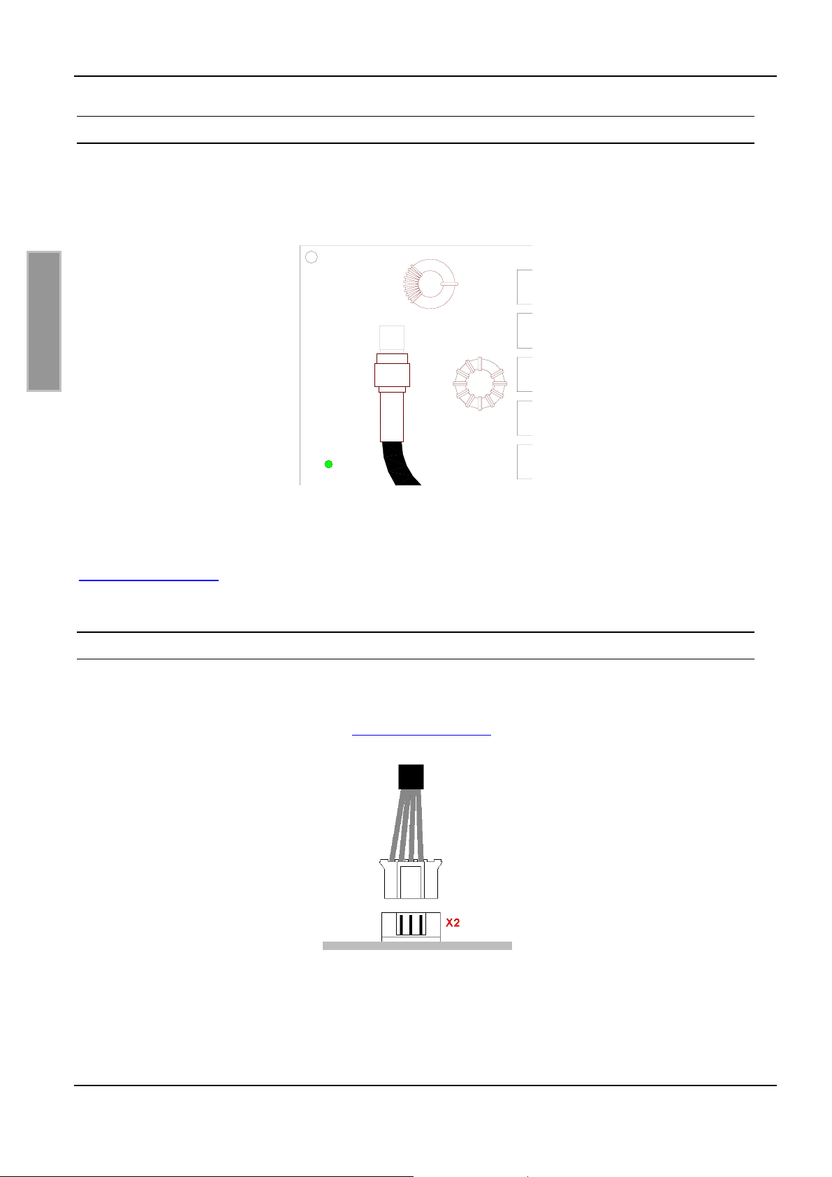
The HF line and the supply voltage are connected as shown in Fig. 5 at SMA socket X1. The
dynamic antenna tuner operates on a DC voltage of 7 - 12V.
X1
E N G L I S H
Fig. 5: HF line and supply voltage connection
The supply voltage of 7 –12 VDC is present as a DC voltage offset on the HF line. See also
5.3.1 Supply voltage.
3.2.2 X2: Boot Loader Interface
To perform a firmware update you have to connect the update cable ID CAB.RS-B with X2 as
shown in Fig. 6. The tuning board must be powered through the antenna cable on X1 as it is done
in the normal operation mode. See also 5.3.1 Supply voltage.
Fig. 6: Connection of the Update Cable
The procedure of the firmware update is described in Application Note ID ISC.DAT – Firmware
Update (N50801-xe-ID-B).
FEIG ELECTRONIC GmbH Page 30 of 44 M40401-4de-ID-B.doc
Page 31
OBID i-scan
®
3.2.3 X3: Outputs OUT1-3
Installation ID ISC.DAT
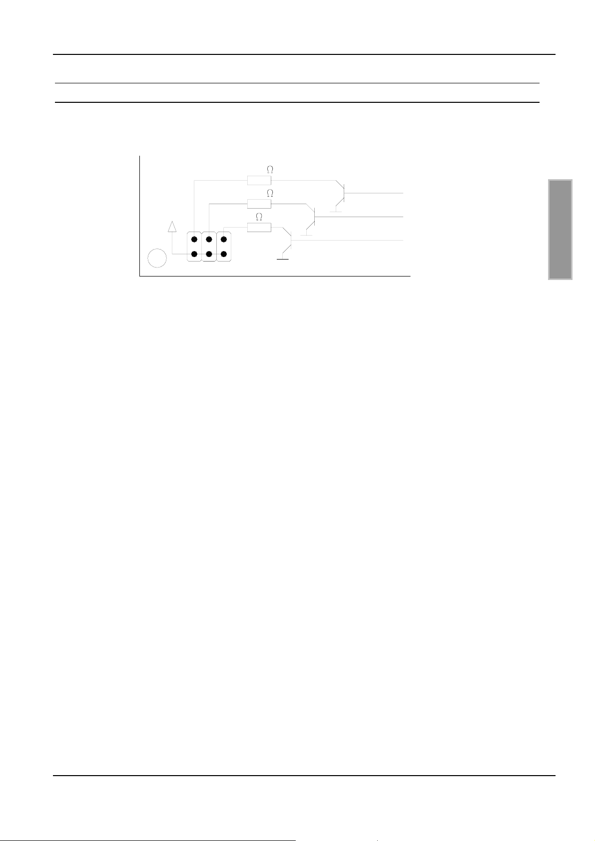
Outputs OUT1-3 can be tapped on terminal X3. The outputs have a load capacity of I
= 15mA
max
(see Fig. 7). It is not possible to activate all three outputs simultaneously.
330
OUT1
OUT2
OUT3
+5VDC
330
0
X3
Fig. 7: Outputs OUT1-3
Note:
The series resistance of OUT3 is 0Ω. Ensure that the current level does not exceed 15mA!
E N G L I S H
FEIG ELECTRONIC GmbH Page 31 of 44 M40401-4de-ID-B.doc
Page 32
OBID i-scan
®
Installation ID ISC.DAT
3.2.4 X6, X7: Connecting the antenna conductor
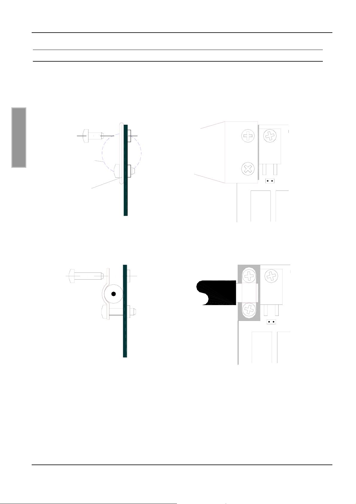
The antenna conductor is connected to the circuit board at X6 and X7.
Fig. 8 shows installation of an antenna cable made of copper tubing (d
and in Fig. 9 for an coaxial cable antenna (RG214).
M3x6
contour copper tubing
X6
E N G L I S H
copper tubing
(crimped)
printed board
Fig. 8: Antenna connection (copper tubing)
= 18mm; ends crimped)
Rohr
X6
JP1
M3x12
RG214
X6
X6
JP1
printed board
Fig. 9: Antenna connection (coaxial cable RG214)
Note:
Ensure that there is good electrical contact between the antenna conductor and the contact
surfaces.
FEIG ELECTRONIC GmbH Page 32 of 44 M40401-4de-ID-B.doc
Page 33
OBID i-scan
®
Installation ID ISC.DAT
4 Operating and Display Elements
4.1 LEDs
The green LED flashes at a frequency of approx. 1 Hz to indicate proper running of the internal
software.
The red LED indicates with a short flash a received protocol.
4.2 Jumpers JP1 and JP2: Setting the Q
Jumpers JP1 and JP2 are used to set the antenna Q.
For Q setting, see 5.2 Setting the Q
4.3 Jumper JP3: Setting the antenna switch
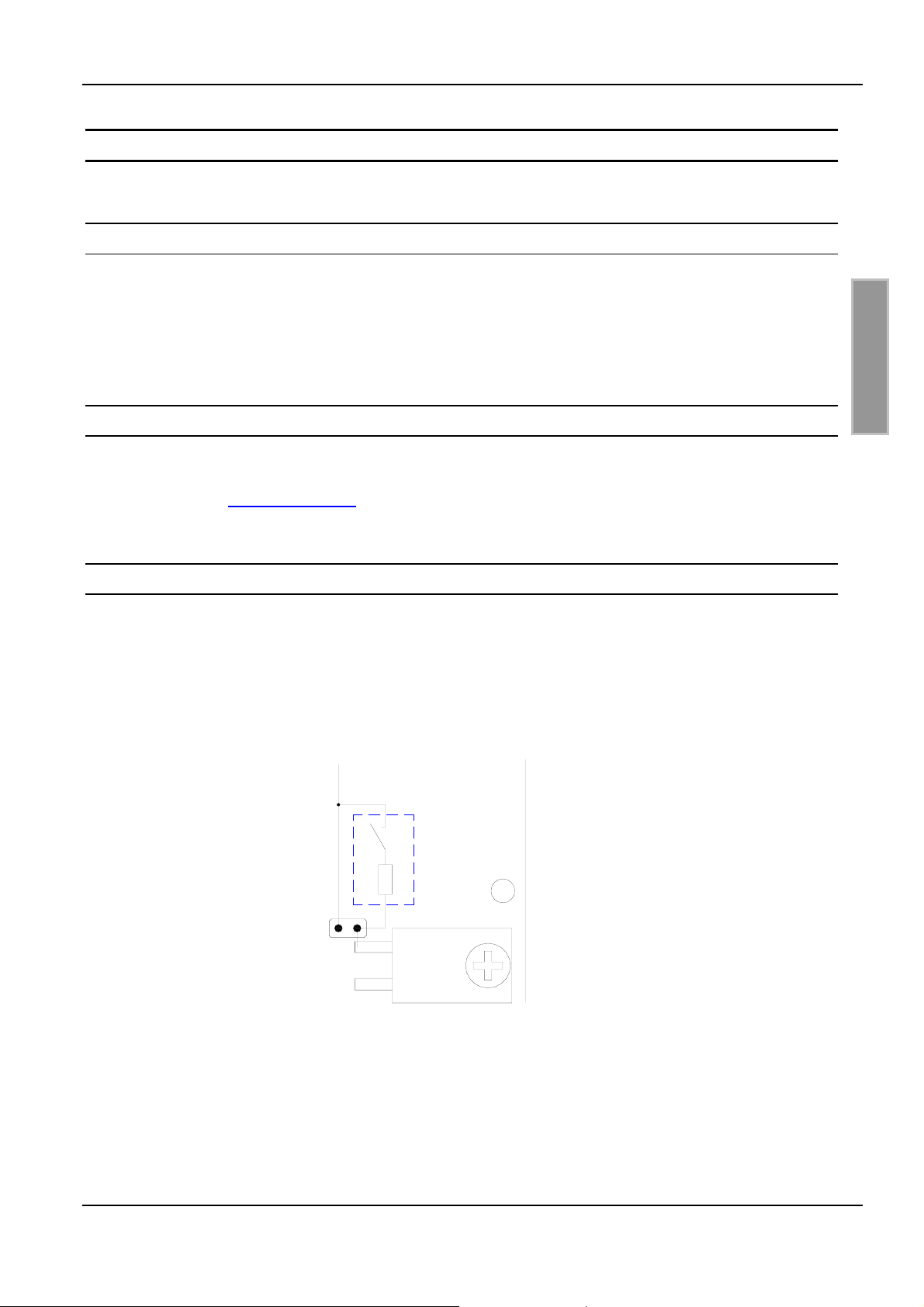
Jumper JP3 is used to short-circuit the switch that detunes the antenna oscillator circuit (see Fig.
10) This is necessary when the antenna needs to be operated without supply voltage or antenna
current is high, see also Table 1.. After a change of the setting of JP3 (opening or closing), a
hardware reset must be done by switching off and on the DC power supply.
switch
E N G L I S H
JP3
Fig. 10: JP3 Antenna switch jumper
FEIG ELECTRONIC GmbH Page 33 of 44 M40401-4de-ID-B.doc
Page 34
OBID i-scan
®
Installation ID ISC.DAT
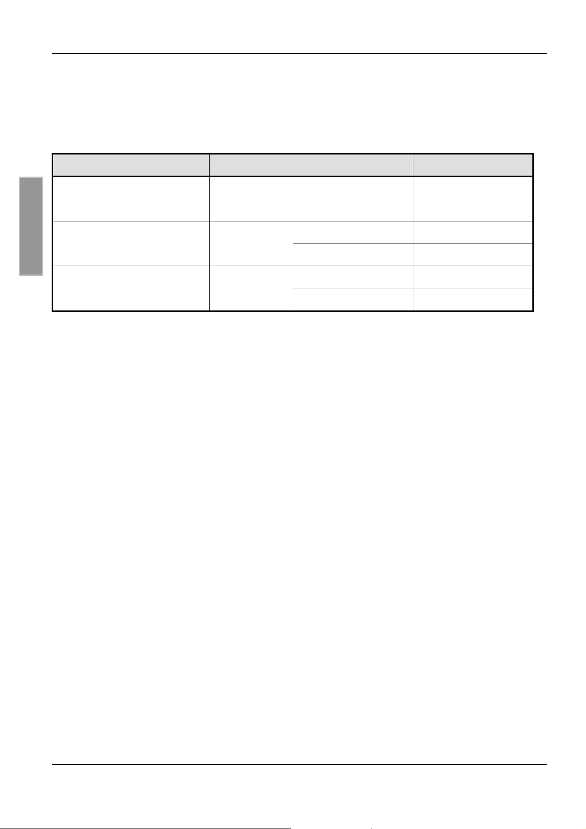
The maximum RF-power for different antennas and quality factors, where usage of the antenna
switch is allowed, is listed in Table 1.
Table 1: maximum RF-power during permanent operation
antenna inductance quality resistance max. RF-power
ID ISCANT300300
(single-loop: 300mm x 300mm)
ID ISCANT800600
(single-loop: 800mm x 600mm)
E N G L I S H
ID ISCANT1400700
(8-antenna: 1400mm x 700mm)
0Ω
0.8µH
3Ω
0Ω
1.9µH
3Ω
0Ω
1.1µH
3Ω
3.5 W
6.5 W
If the tuning board is not permanently applied with RF-power (for example while working with a
multiplexer) the maximum power increases.
7 W
6 W
3 W
8 W
FEIG ELECTRONIC GmbH Page 34 of 44 M40401-4de-ID-B.doc
Page 35
OBID i-scan
®
Installation ID ISC.DAT
5 Startup
5.1 Presetting the calibration capacitances
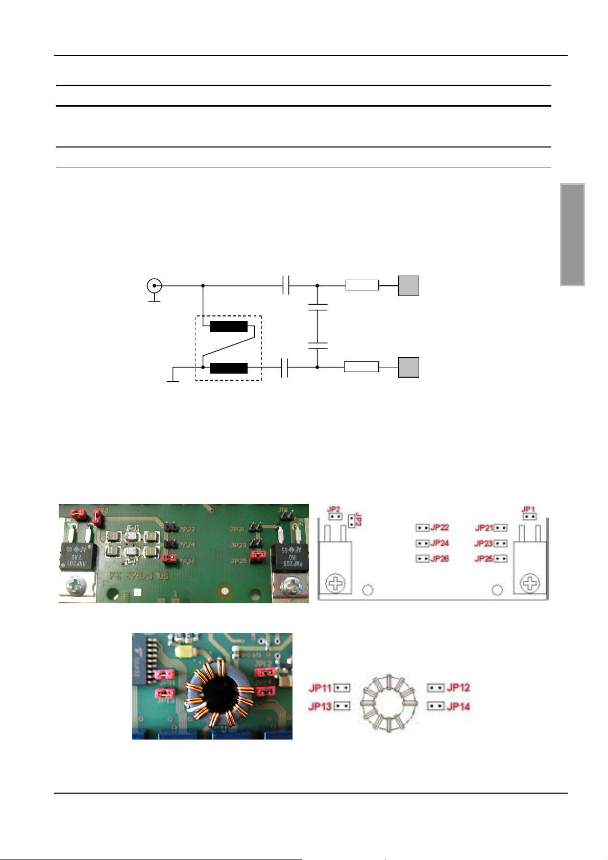
The antenna is tuned using a matching circuit consisting of capacitors C1x (C11, C12) and C2x
(C21, C22) and a transformer which is wired as a balun for balancing the antenna current. The
capacitors for balancing are divided into C11 and C12 (for C1x) and C21 and C22 (for C2x). A
substitution diagram for the compensation circuit with balloon is shown in Fig. 11.
E N G L I S H
Fig. 11: Substitution diagram for matching circuit with balun
The matching capacitors can be enabled by fitting the jumpers JP21...JP26 and JP11...JP14 (from
hardware version FE575/3) used to enable the capacitors for presetting the matching capacitors
C1x and C2x.. See Fig. 12 and Fig. 13.
Fig. 12 Additional jumper for JP21 to JP26 on hardware version FE575/3
Fig. 13 Additional jumper JP 11 to JP14 on hardware version FE575/3
FEIG ELECTRONIC GmbH Page 35 of 44 M40401-4de-ID-B.doc
Page 36
OBID i-scan
®
Installation ID ISC.DAT
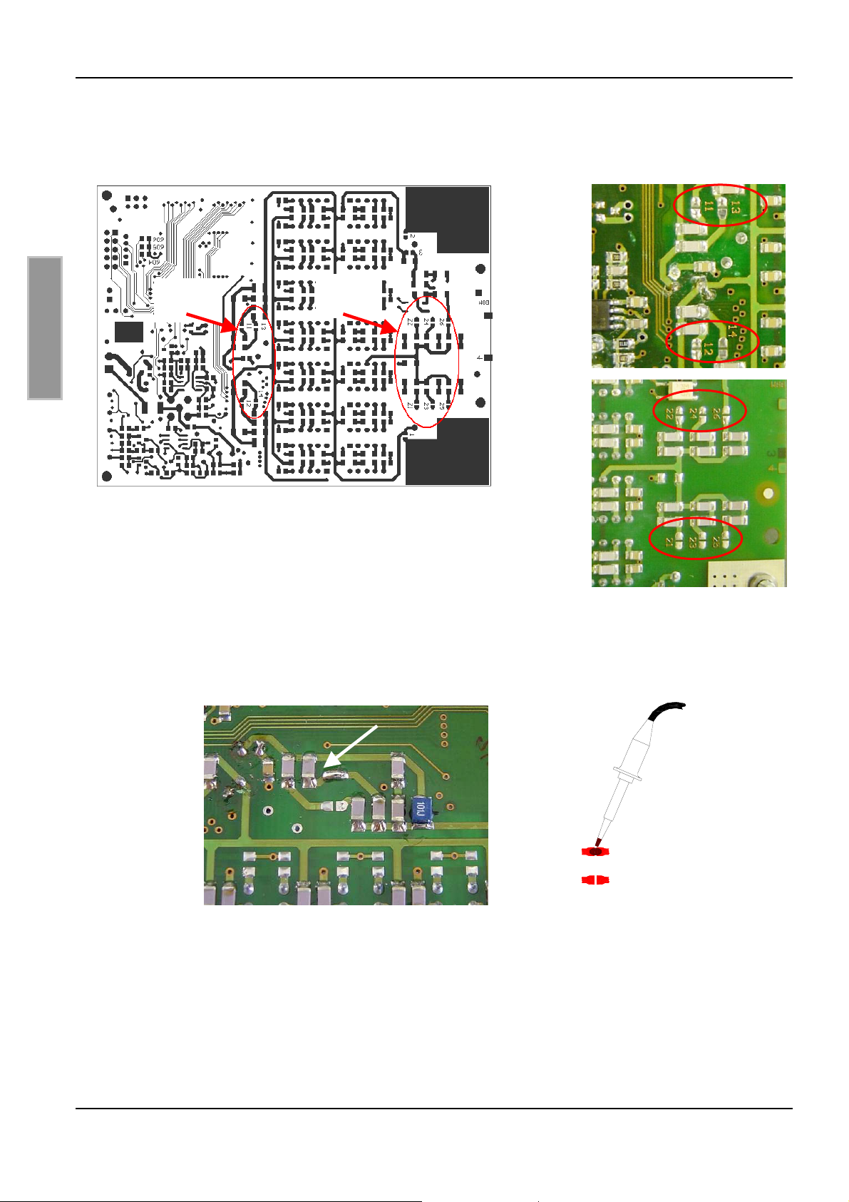
Alternatively solder jumpers can be used. The solder jumpers are numbered on the underneath
side of the board (see Fig. 14).
C1x:
(11-14)
C1x
C2x
E N G L I S H
C2x:
(21-26)
Fig. 14: Solder jumpers for the matching capacitors on underneath side
Fig. 15 shows closing the solder jumpers with the soldering iron and a closed solder connection:
11
13
11
13
Fig. 15: Closing solder jumper 11
FEIG ELECTRONIC GmbH Page 36 of 44 M40401-4de-ID-B.doc
Page 37
OBID i-scan
®
Installation ID ISC.DAT
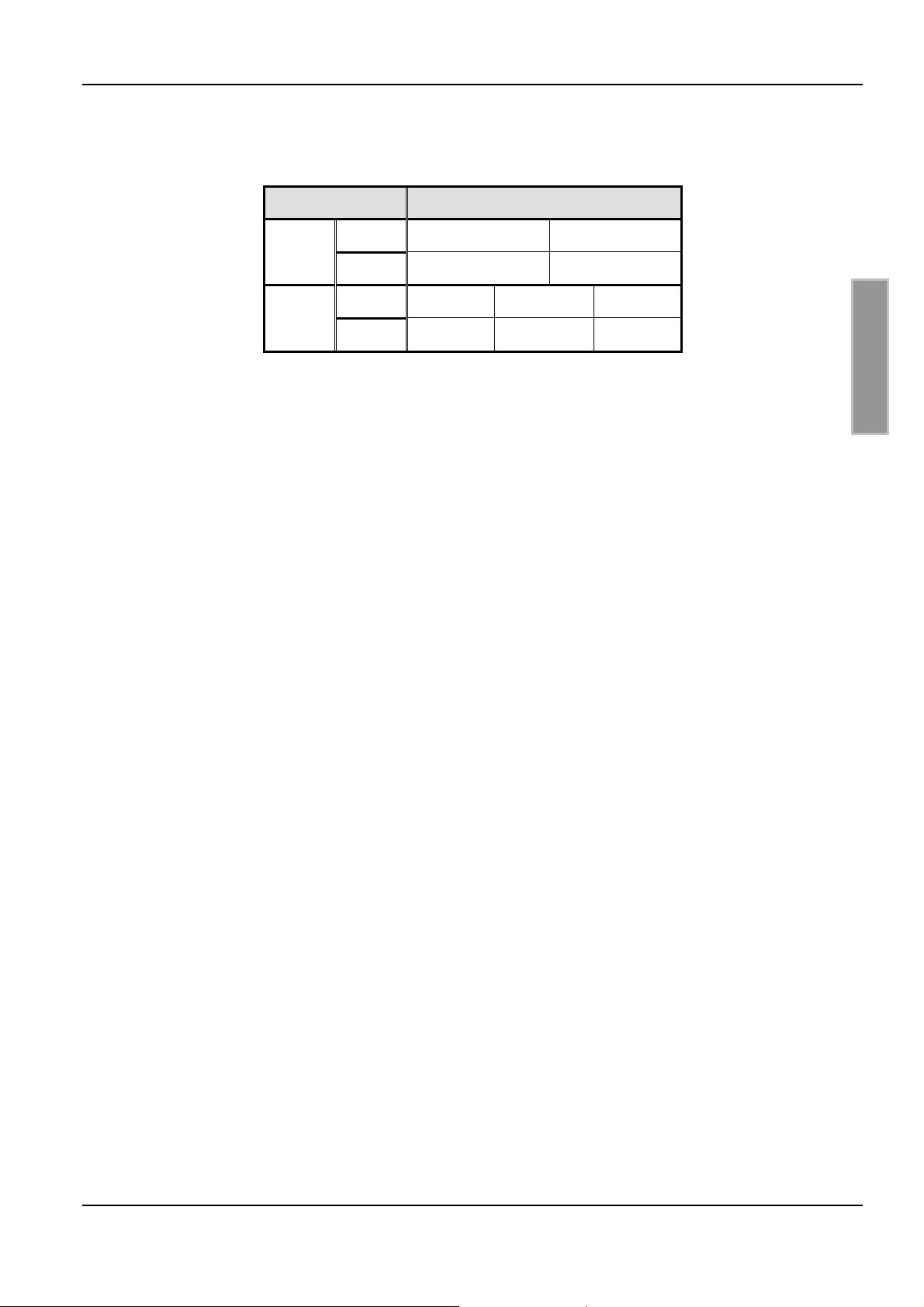
Table 2 summarizes the capacities enabled by the corresponding jumpers and solder jumpers:
Table 2: Jumper JP11-26
Jumpers / Solder jumpers
C11 11: 17pF 13: 33pF
C1x
C12 12: 17pF 14: 33pF
C21 21: 165pF 23: 82pF 25: 41pF
C2x
C22 22: 165pF 24: 82pF 26: 41pF
Note:
Due to the symmetry the values C11 / C12 and C21 / C22 must always be the same. This
means for C11 and C12 that solder jumpers 11 / 12 and 13 / 14 must always to connected or
open. The same applies for C21 and C22..
E N G L I S H
FEIG ELECTRONIC GmbH Page 37 of 44 M40401-4de-ID-B.doc
Page 38
OBID i-scan
®
Installation ID ISC.DAT
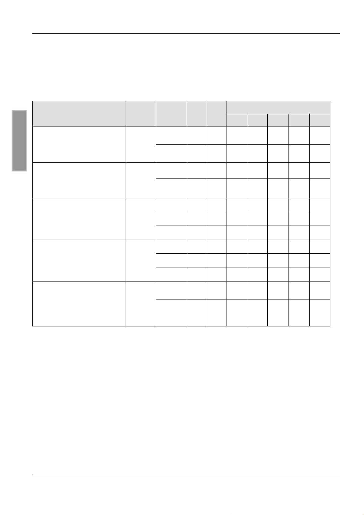
The value for the presetting depends on the inductance and Q of the antenna you are tuning. Table
3 lists the presetting for common antennas. Q describes the quality factor for the antenna at the
different resistors (R1 + R2) which had been set by jumpers. C1x and C2x is the value you will get
with the ISO-Start command “Get antenna value” after a successful tuning of the antenna.
Table 3: Presetting the capacitance’s
Feig- Standard antennas
ID ISCANT300300
(Single-Loop: 300mm x 300mm)
aluminium tape 20mmx 1,5mm
E N G L I S H
ID ISCANT800600-DA
(Single-Loop: 800mm x 600mm)
18mm copper pipe
ID ISCANT1300680-A
(8-Antenne: 1300mm x 680mm)
10mm aluminium pipe solid material
ID ISCANT1400760-A/B/C
(8-Antenne: 1400mm x 700mm)
18mm copper pipe
L / µH
0,8
1,9
1,2
1,1
Q
(R1,R2)
56 (0Ω)
10 (3Ω)
50 (0Ω)
21 (3Ω)
57 (0Ω)
33 (1Ω)
16 (3Ω)
56 (0Ω)
33 (1Ω)
15 (3Ω)
C1x C2x
66 55
43 76
26 50
66 36
47 91
70 82
38 64
46 86
74 79
46 60
Jumper / Solder bridge (closed)
11/12 13/14 21/22 23/24 25/26
z z
z z z
z
z
z
z
z z
z z
z z
z z z
SLA/SLB
(Single Loops: 1400mm x 700mm)
18mm copper pipe
2,2
42 (0Ω)
23 (3Ω)
39 82ID ISCANT1400760-
59 77
FEIG ELECTRONIC GmbH Page 38 of 44 M40401-4de-ID-B.doc
Page 39
OBID i-scan
®
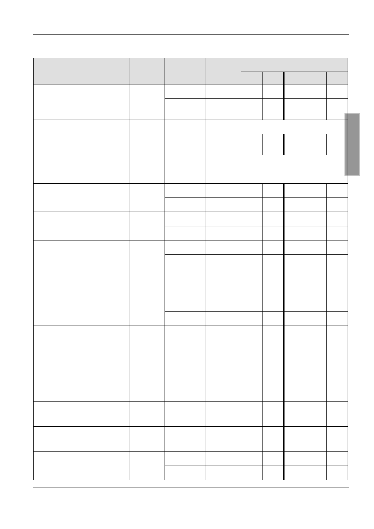
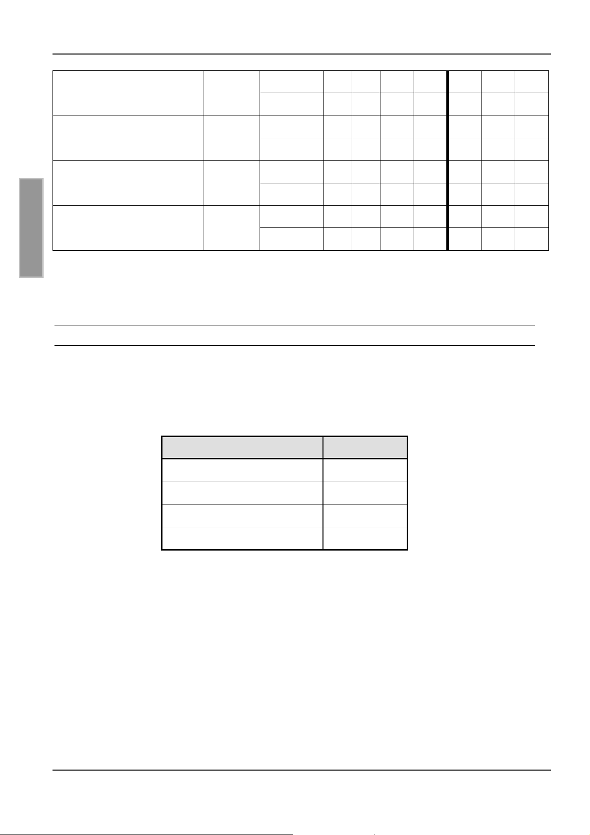
Further examples:
Installation ID ISC.DAT
Copper pipe antenna (∅
18mm)
Single-Loop 1200mm x 650m
Coaxial cable antenna
(RG213)
Single-Loop ∅ 250mm
Copper adhesive tape 25mm
Single-Loop 250 x 250mm
Copper adhesive tape 25mm
Single-Loop 300 x 300mm
Copper adhesive tape 25mm
Single-Loop 400 x 250mm
L / µH
2,5
0,5
0,5
0,66
0,75
Q
(R1,R2)
42 (0Ω)
23 (3Ω)
55 (0Ω)
8 (3Ω)
(0Ω)
(3Ω)
43 (0Ω)
9 (3Ω)
55 (0Ω)
10 (3Ω)
C1 C2
Jumper / Solder bridgeAntenna
11/12 13/14 21/22 23/24 25/26
29 47
50 39
65 110 Tuning range C2 to low
67 125
z z z z z
Tuning range C1 and C2 to low
82 56
84 76
68 70
64 85
z z z
z z z
z z z
z z
E N G L I S H
Copper adhesive tape 25mm
Single-Loop 500 x 500mm
Copper adhesive tape 25mm
Single-Loop 600 x 400mm
Copper adhesive tape 25mm
Single-Loop 600 x 600mm
Copper adhesive tape 25mm
Single-Loop 1000x300mm
Copper adhesive tape 25mm
Single-Loop 1060x400mm
Copper adhesive tape 25mm
8-Antenne 2 x 600x340mm
Copper adhesive tape 8mm
8-Antenne 2 x 400x400mm
1,36
1,36
1,7
1,8
2,4
0,7
0,5
55 (0Ω)
17 (3Ω)
53 (0Ω)
16 (3Ω)
34 (0Ω)
13 (3Ω)
33 (1Ω)
33 (1Ω)
21 (1Ω)
(1Ω)
40 84
25 60
42 83
28 58
50 76
83 65
48 70
44 29
53 94
113 92
z
z z
z
z z
z
z
z
z
z z z
z z z
Copper adhesive tape 8mm
z
z z
8-Antenne 2 x 500x500mm
Copper adhesive tape 8mm
0,68
(0Ω)
52 (0Ω)
70? 70?
68 52
0,8
Single-Loop 250 x 250mm
10 (3Ω)
64 68
z z z
FEIG ELECTRONIC GmbH Page 39 of 44 M40401-4de-ID-B.doc
Page 40
OBID i-scan
®
Installation ID ISC.DAT
Copper adhesive tape 8mm
46 (0Ω)
66 70
0,98
Single-Loop 300 x 300mm
Copper adhesive tape 8mm
13 (3Ω)
46 (0Ω)
74 41
48 74
z z
1,4
Single-Loop 400 x 400mm
Copper adhesive tape 8mm
15 (3Ω)
44 (0Ω)
32 51
40 67
z z
1,8
Single-Loop 500 x 500mm
Copper adhesive tape 8mm
19 (3Ω)
38 (0Ω)
76 55
40 83
2,3
Single-Loop 600 x 600mm
20 (3Ω)
64 74
E N G L I S H
5.2 Setting the Q
The Q is set using jumpers JP1 and JP2. Setting the jumpers enables the parallel installed
resistors.
z
z
z
z
Table 4 lists the possible resistance settings.
Table 4: Q resistance
Jumper R1 + R2
JP1 and JP2 closed
JP1 open, JP2 closed
JP1 closed, JP2 open
JP1 and JP2 open
0 Ω
1 Ω
2 Ω
3 Ω
FEIG ELECTRONIC GmbH Page 40 of 44 M40401-4de-ID-B.doc
Page 41
OBID i-scan
®
Installation ID ISC.DAT
5.3 Connecting and tuning
5.3.1 Supply voltage
A power supply connected through the HF line is required for operation and for the calibration
procedure. The supply voltage can be looped into the HF line in various ways:
1. Multiplexer
If the antenna is operated on a FEIG Multiplexer ID ISC.ANT.MUX, the latter can be configured
such that up to two ID ISC.DAT antenna tuners can be powered at the same time over the HF line
(see Installation Manual ID ISC.ANT.MUX
output on the multiplexer.
2. Power-Splitter
2
). The antenna tuner is then connected directly to an
E N G L I S H
The FEIG-Power-Splitter ID ISC.ANT.PS-B can be configured such that it can power one or two
3
connected ID ISC.DAT antenna tuners (see Installation Manual ID ISC.ANT.PS-B
).
3. Reader with DC voltage offset
If the connected Reader has a DC voltage offset of 7-12V (current draw 150mA, see User’s
Manual for Reader ID ISC.LR2000, LRM2000, MR200 ), the ID ISC.DAT antenna tuner can be
connected directly to the Reader.
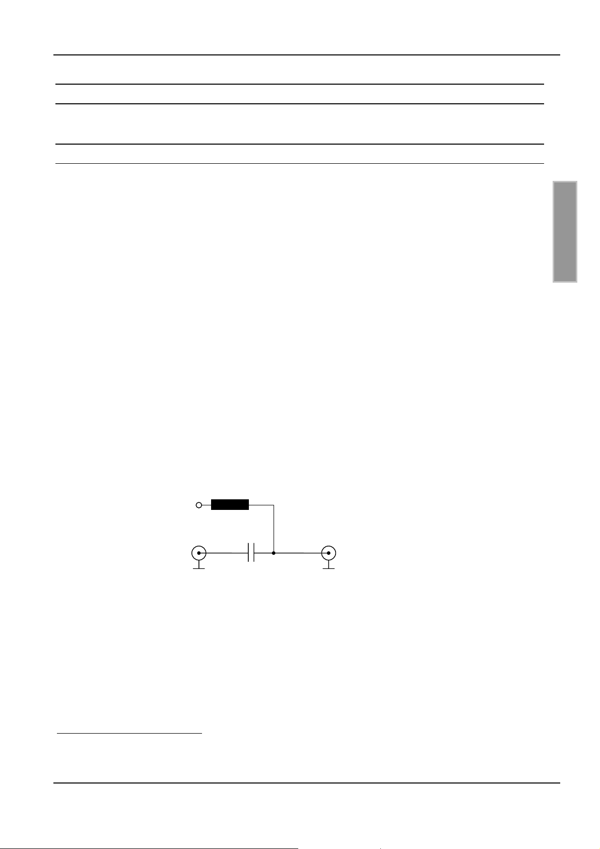
If none of the above options are available, apply the DC voltage to the HF cable as shown in Fig.
16.
7-12V
DC
L: 10uH Epcos SIMID03 (B82432-A1103-K)
C: 100nF
Fig. 16: Providing supply voltage
2
Installation Manual Antenna Multiplexer M30201-xde-ID-B
3
Installation Manual Power-Splitter M40402-xde-ID-B
FEIG ELECTRONIC GmbH Page 41 of 44 M40401-4de-ID-B.doc
Page 42
OBID i-scan
®
Installation ID ISC.DAT
5.3.2 Tuning the antenna
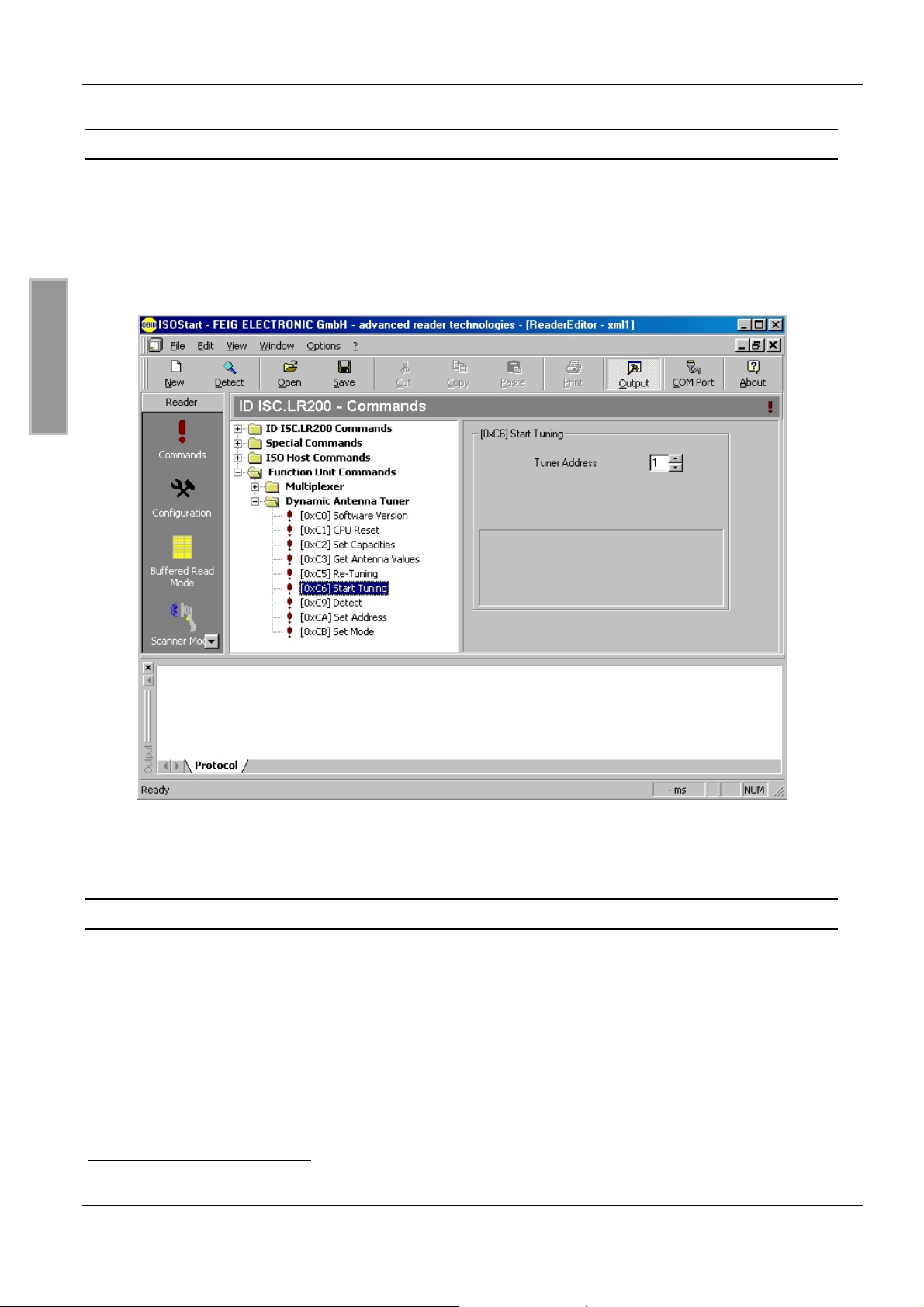
The ID ISC.DAT antenna tuner is controlled via protocols4 from the Reader and from the host. The
protocols are incorporated in the demo program ISOStart (V 06.07 and higher) (see Fig. 17).
The first time the device is used you perform „Start Antenna Tuning“. Retuning can be carried out
using a „Re-Tuning“ function. For more complex antenna configurations you must first assign
individual addresses using the “Set Address” function. The factory set standard address is 01.
E N G L I S H
Fig. 17: ISOStart (V06.07 and higher) Function Unit Commands ⇒ Dynamic Antenna Tuner
For the tuning of antenna systems the software „DATuningTool.exe“ can be used.
5.4 Operating without power supply
A tuned antenna can also be operated without power supply. For this the antenna switch must be
jumpered by inserting jumper JP3.
Note:
Settings or parameter queries for the ID ISC.DAT antenna tuner are possible only when
using a power supply
4
See Communication FU manual: H30701-xe-ID-B.doc
FEIG ELECTRONIC GmbH Page 42 of 44 M40401-4de-ID-B.doc
Page 43

OBID i-scan
®
6 Technical data
Mechanical Data
Installation ID ISC.DAT
• Dimensions ( W x H x D )
• Weight
Electrical Data
• Supply voltage
• Current consumption
• Operating frequency
• maximum transmitting power
• Antenna switch
• Antenna connection
• RF connection
118 mm x 90 mm x 19 mm
(4.65inch x 3.54inch x 0.75inch)
approx. 100 g (0.22lb)
E N G L I S H
7 - 12 V DC
max. 150mA (DC)
13.56 MHz
10 W**
electronic switch
(note max. antenna current)
cable terminals d = 2 – 9mm
SMA male (50 Ω) *
• Triggering
• Outputs
• Signal indicator
• Interface
Antenna parameter
• Carrier frequency
• Impedance
• tuning range inductance
• quality
* maximum tightening torque: 0.45Nm
Table1
** See
Reader: Communication via RF-connection
3 x Open Collector: 5 V DC/ max. 15 mA
1 x „RUN“-LED (green), 1x “Protocol”-LED (red)
RS232 TTL (for Firmware Update)
13.56MHz
50Ω
0.7 – 2.5µH
10 – 50
FEIG ELECTRONIC GmbH Page 43 of 44 M40401-4de-ID-B.doc
Page 44

OBID i-scan
®
Ambient Conditions
• Temperature range
– Operating
– Storage
Installation ID ISC.DAT
-25°C to +75°C (-13°F to +167°F)
-40°C to +80°C (-40°F to +176°F)
• EMC
• Vibration
• Shock
EN61000-6-3
EN61000-6-2
EN60068-2-6
10 Hz to 150 Hz :0.075 mm / 1 g
EN60068-2-27
Acceleration : 30 g
E N G L I S H
6.1 Approval (CE)
When properly used this radio equipment conforms to the essential requirements of Article 3 and
the other relevant provisions of the R&TTE Directive 1999/5/EC of March 99.
Electromagnetic compatibility (EMC) –
Generic emission standard;
Part 6-3: Generic standards – Emission standard for residential,
commercial and light industry
Electromagnetic compatibility (EMC) –
Part 6-2: Generic standards – Immunity of industrial environments
EN 61000-6-3:2001
EN 61000-6-2:2001
FEIG ELECTRONIC GmbH Page 44 of 44 M40401-4de-ID-B.doc
 Loading...