

Page 1
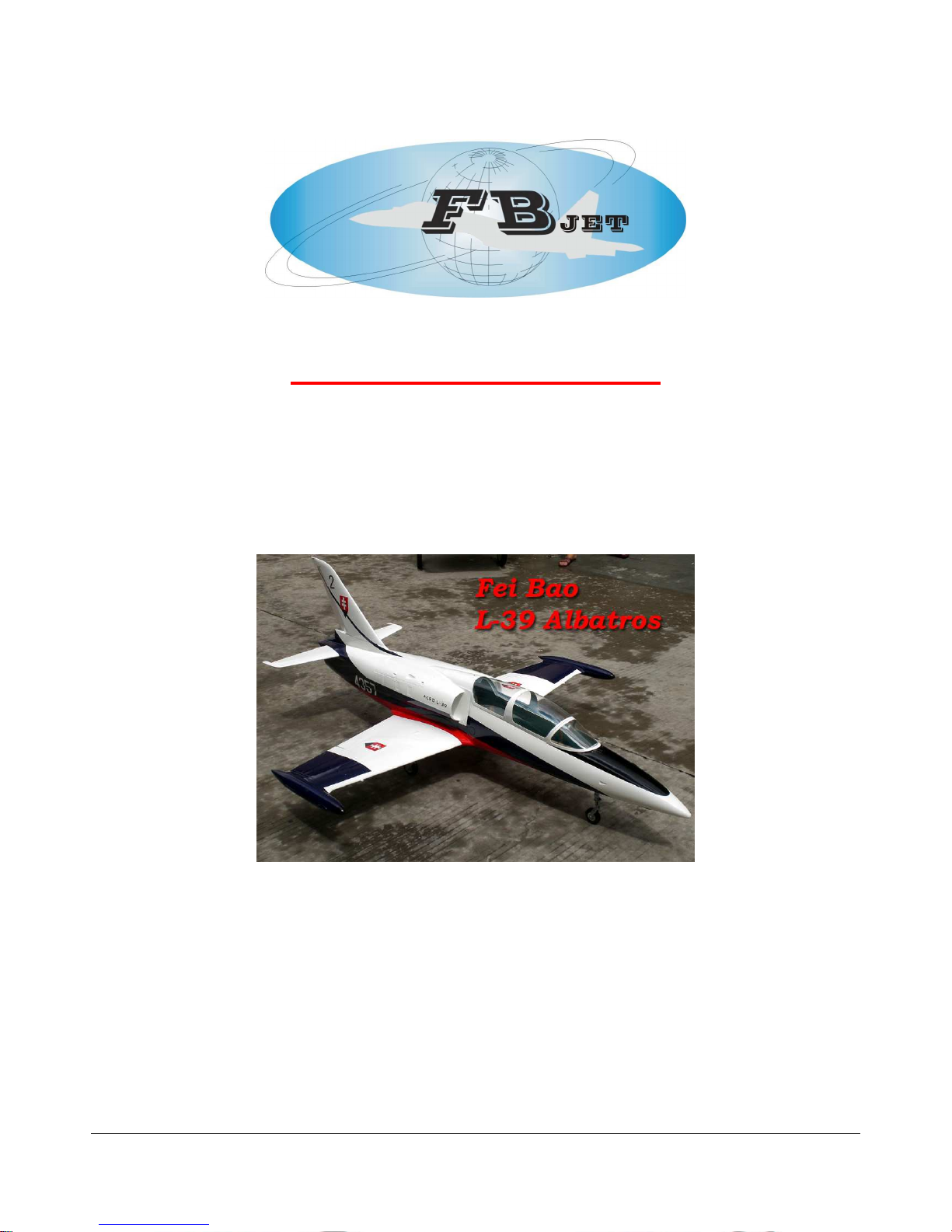
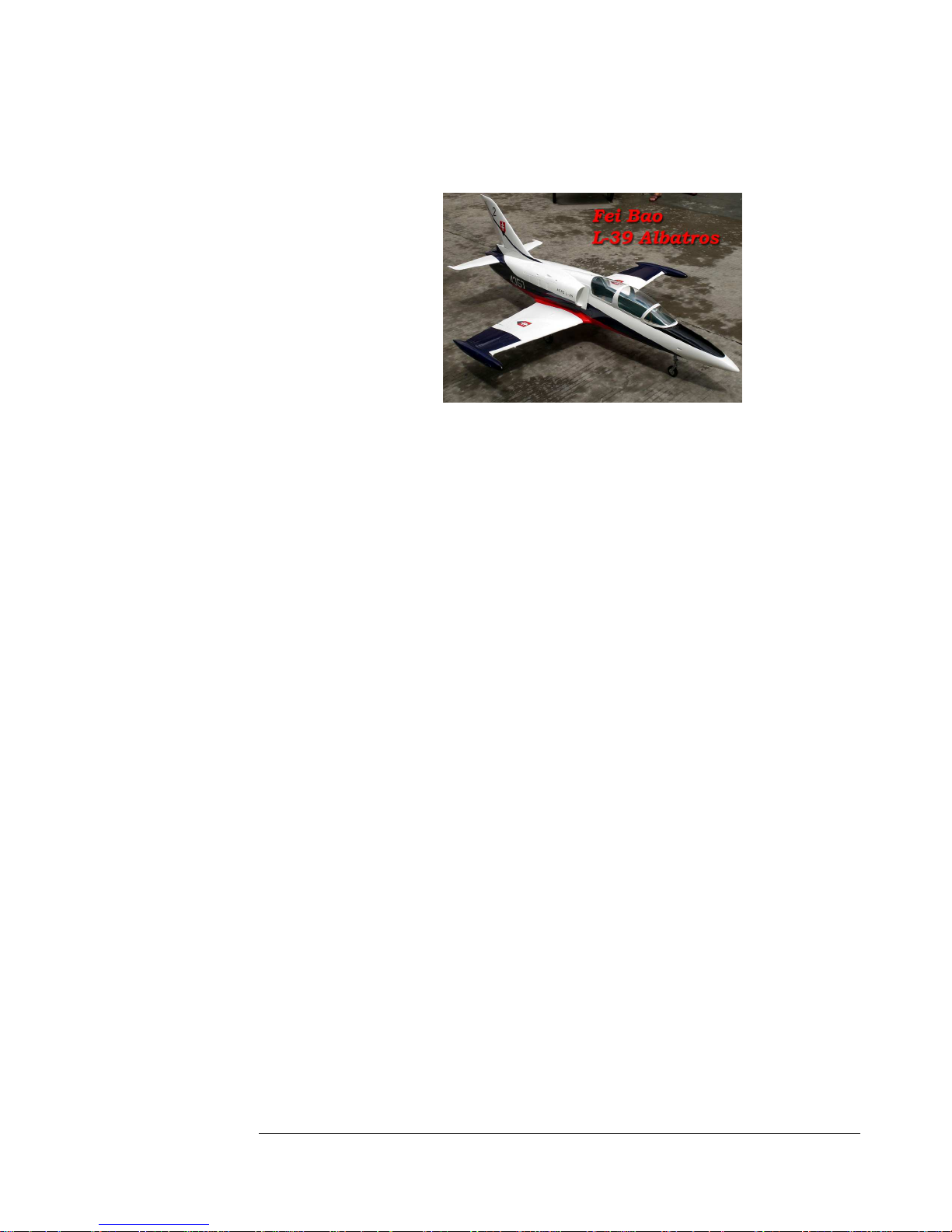
F E I B A O L - 3 9 A L B A T R O S
FEI BAO JETS
L-39 Assembly Manual
Written by Curtis Mattikow
In collaboration with R/C Jet Models
1111
Page 2

F E I B A O L - 3 9 A L B A T R O S
2222
DISCLAIMER:
THIS IS NOT A TOY. This is a high-performance miniature aircraft, capable of
high speeds and damage to life, limb, and property. The manufacturer and its
distributors cannot control how you assemble this model, what equipment you use
to fit it out, or how you fly it, and can assume no liability whatsoever for any
damages that may occur when you fly your aircraft. By assembling this model,
you are agreeing to indemnify and hold blameless the manufacturer and/or his
agents from any and all torts and liability associated with the use of this product.
Please inspect all parts before beginning assembly. If any parts appear to be
suspect, contact your dealer or the manufacturer for repair or replacement
BEFORE you begin. Once you have assembled the aircraft, you are the pilot in
command and assume any and all responsibility for the use of the model and any
damages that might occur by flying or attempting to fly this aircraft.
R/C model jets require a high level of skill in both their assembly and their flying.
If you do not feel confident in either your building or flying skills, PLEASE seek
assistance from more experienced modelers. It is a wise idea, no matter what level
of skills you possess, to have a second experienced modeler go over your
installation after assembly. A second set of eyes may spot a problem you have
missed. If you have not flown a model like this before, it is HIGHLY
recommended that you get an experienced turbine pilot to do your maiden flight.
Very often, the first few seconds of a maiden flight are critical until the aircraft is
trimmed out, and having an experienced pilot at the controls can make the
difference between a wrecked aircraft and once that enjoys many hundreds of
flights. Be sure to select a suitable field for flying...take the time to find a large
paved runway if at all possible, especially for test flights, until you feel comfortable
getting the aircraft in and out of smaller grass fields.
BEFORE YOU BEGIN:
Keep this in mind as you proceed:
Look at EVERY assembly step you finish, and ask yourself:
"Is this going to crash my airplane?"
A chain is only as strong as its weakest link, and this is a high-performance aircraft
that will be very intolerant of sloppy assembly techniques. Even the smallest
component is important and can cause the loss of your airplane, so take the time
to do things right. Or REdo them if they are wrong. Careful work will result in a
long-lasting plane that gives you years of pleasure, one loose component could
result in the complete loss of the aircraft and all the components inside it, and
someone can even get hurt. So pause every once in a while when building it and
double-check your workmanship.
Page 3

F E I B A O L - 3 9 A L B A T R O S
3333
A. Introduction:
You have chosen a model that represents the pinnacle of ARF technology. While
there is not a lot of building to do, there is enough to keep you busy for a few
evenings.
Even if you have assembled maybe other ARF jets, we highly recommend
following our assembly sequence and procedures anyway.
Chances are it will save you a lot of time, prevent you from running down dead
ends, and perhaps remind you of a few small things that might end up saving your
aircraft.
We have tried to arrange a construction sequence that will allow you to keep
moving forward, rather than standing around waiting for glue to dry before you
can proceed to the next step.
Just because the model is almost completely built does not mean you can rush
through the final assembly.
You need to employ fine craftsmanship every step of the way, turbine models are
critical. Keep this in mind with everything you do, every part you install...look at
the work you just did, evaluate it critically, and ask yourself "is this going to
potentially crash my airplane?" If there is any doubt about the work you have
done, back up, and re-do it properly.
B. Adhesives:
The correct adhesive to use for all procedures is Loctite Hysol 9462. This is a
very strong white epoxy that is thixotropic. "Thixotropic" means it does not run
at all, but stays only where you put it. It is infinitely superior to regular epoxy,
even slow-setting epoxy, for our purposes, because of this characteristic.
Regular epoxy will run downhill with gravity as it dries, taking it away from where
it is supposed to be.
A good example is in the hinges...using regular epoxy, a good portion of the glue
will migrate down away from the hinge into the inside of the wing as it dries, and
you won't even know it is happening. Hysol stays where you put it.
The downside of Hysol is it takes overnight to dry properly, but we have tried to
arrange things to keep you busy while waiting for glue to dry.
We also highly recommend that you only use a proper Hysol dispensing gun, and
only the long-type mixing nozzles.
The short nozzles do not mix this glue enough, and only a thin nozzle and gun
will let you fill the hinge and control horn holes properly with glue, you can't do it
mixing your Hysol on a flat surface and trying to get the glue in the proper place
by a brush or stick.
You can buy a complete Hysol setup with a gun, nozzles, and two cartridges of
glue from your dealer for approximately $60.
Consider it a great investment, the glue is the best you will use. One cartridge is
plenty to assemble your Velox.
Page 4
F E I B A O L - 3 9 A L B A T R O S
4444
C. WORKING WITH PNEUMATIC SYSTEMS:
The L-39 uses pneumatic brakes and retracts. If you follow a few tips, you should
have very reliable, leak-free operation. Neatness counts.
All airlines should be secured to the airframe to keep them from flopping around
or getting kinked. Use tie wraps for this.
The other very important thing is to cut off the end of each airline dead square
before installing it on the nipple.
This is VITAL. You can either purchase a professional tubing cutter from your
dealer (they are approximately $10), or you can make up a little jig to hold the
airline and keep a sharp, new razor blade perfectly upright as you cut.
Either one works, just ensure that all ends of all airlines are cut off dead square.
Make sure all airlines are pushed ALL THE WAY onto their nipples.
They should not need to be secured otherwise, but you can add fine wire safety
wraps if you like. Make sure all left and right matching airlines are the same
length, particularly the brake lines, or you will get uneven retraction or braking
action.
It's worth taking the time to get everything pneumatic right the first time, as
having your landing gear fail to retract is not THAT bad, but having it fail to
deploy can really ruin you day and the paint on the bottom of your model.
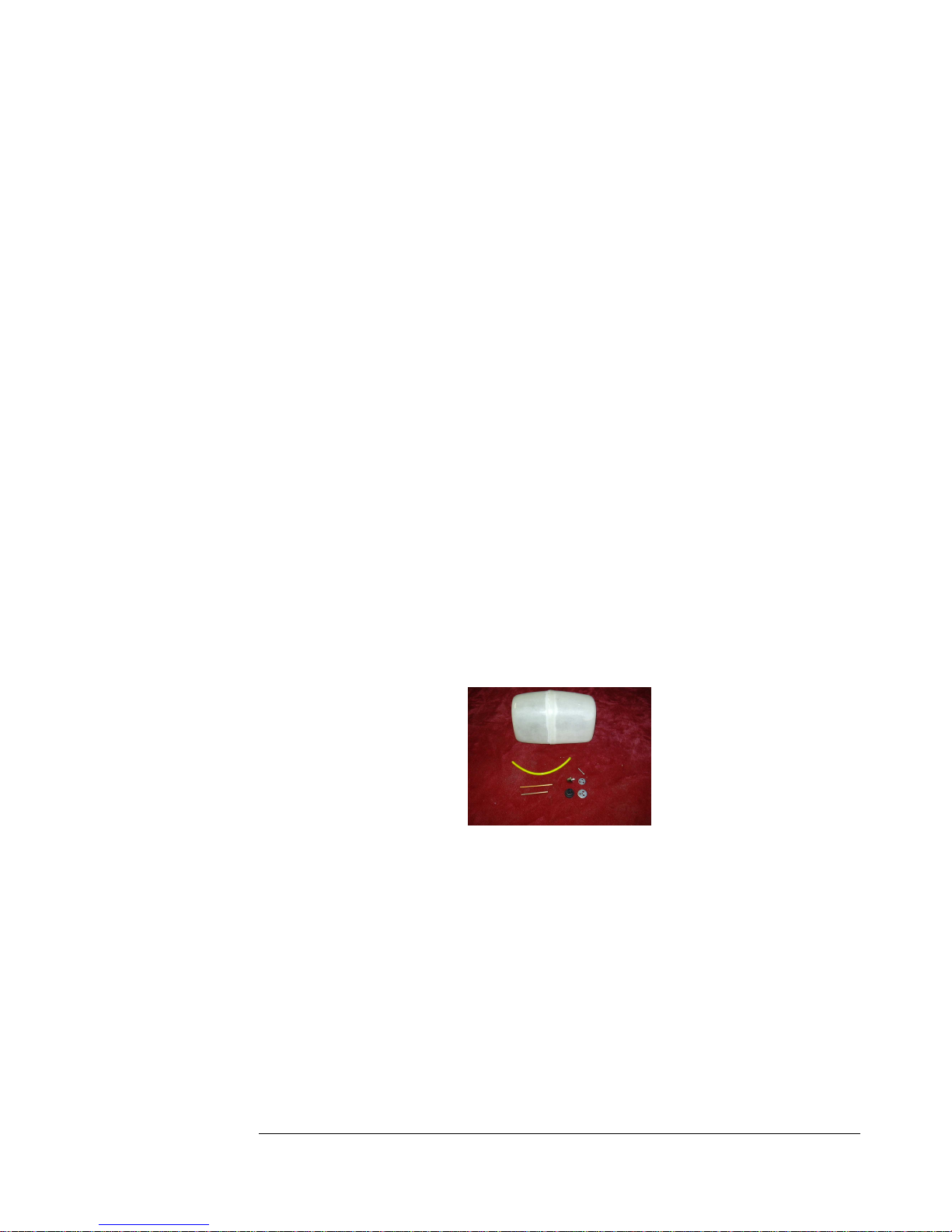
D. FUEL SYSTEM:
The L-39 has a very simple fuel system...one main tank leading to a UAT or
similar header tank.
There is not much to go wrong, but like the pneumatic system, it does need to be
done right the first time, with some careful craftsmanship.
Like the airlines, all fuel lines must be cut off Dead Square. Each fuel connection
should be given a tie-wrap or two for extra security.
Everything needs to be dead clean, especially the inside of the main tank.
The front tray is set up to accommodate a BVM Ultimate Air Trap or it's
equivalent, to keep any bubbles from getting to your engine.
You can also make up your own header tank with a bubbles filter, or a
geometrically centered pickup, but any way you do it, you should not attempt to
fly without a header tank system.
Page 5
F E I B A O L - 3 9 A L B A T R O S
5555
5. Hinging the control surfaces:
While there are many ways of doing this, this method will let you do all the
surfaces at once, assures proper alignment and movement, and let you move on to
other assembly work while the glue on the hinges dries.
Most techniques involve gluing one side of the hinges, letting it dry and then
doing the other side the next night. This lets you do both sides at once, and
guarantees proper alignment. Follow the procedure fully for best results.
Put a towel or cloth down on your bench to keep the airplane from being
scratched. Locate all the control surfaces to their correct place on the wings
and tails. Note that the factory has kept some hinges in place on the control
surfaces to help you locate which surface goes where, left and right. Check
for proper mating, hinge location, and movement on all surfaces. Start with
one wing. Remove the control surfaces and remove the hinges.
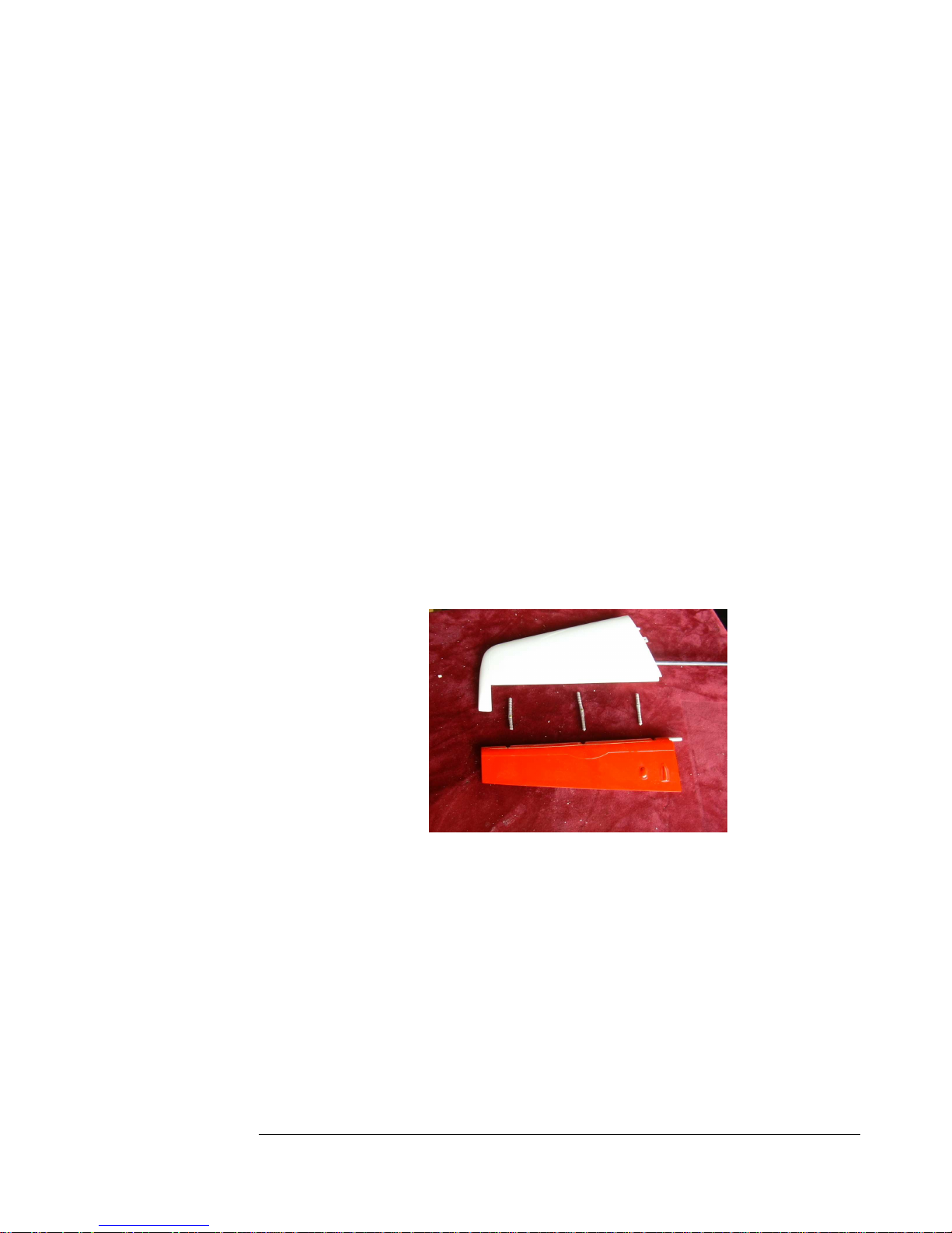
1. Remove the elevators and their hinges from the stabs. You will need to
shorten two of the hinges as Shown.
Figure 1
Page 6
F E I B A O L - 3 9 A L B A T R O S
6666
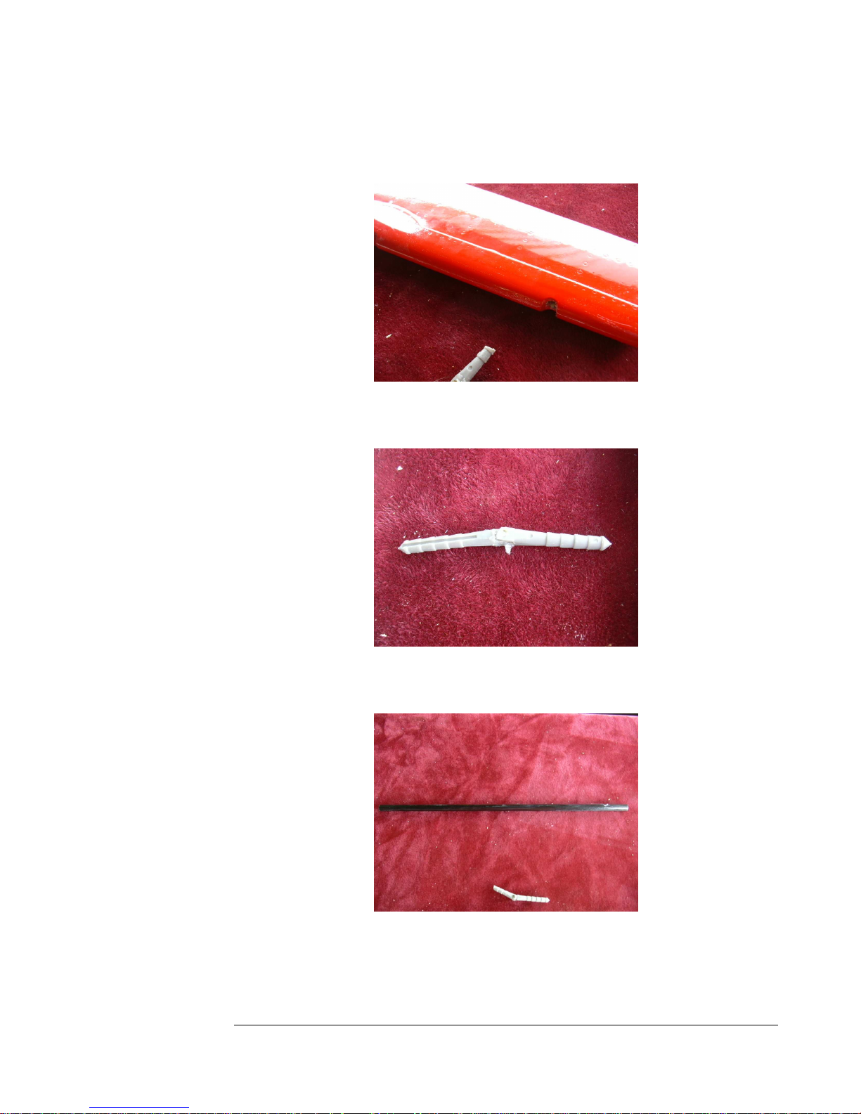
2. Coat the leading edge of the elevator with a thin layer of vaseline to keep
any glue from sticking to it.
Figure 2
3. Coat the center point of each hinge with vaselene also.
Figure 3
4. Coat the carbon fiber stab spar with Vaseline.
Figure 4
Page 7
F E I B A O L - 3 9 A L B A T R O S
7777
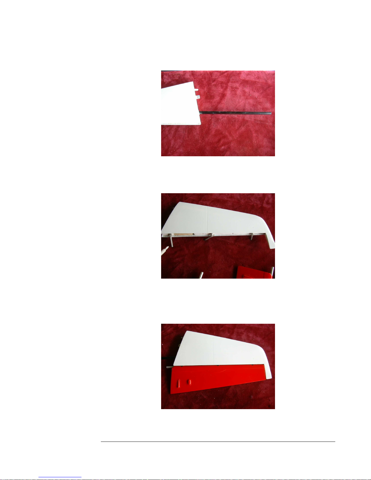
5. Insert the stab spar into one of the stabs.
Figure 5
6. Fill each hinge hole with hysol. Coat each hinge with hysol and insert
into place.
Figure 6
7. Fill the hinge holes in the elevators with glue, coat the hinges with glue,
and press the elevator into place. Carefully check alignment and free
movement.
Figure 7
Page 8
F E I B A O L - 3 9 A L B A T R O S
8888
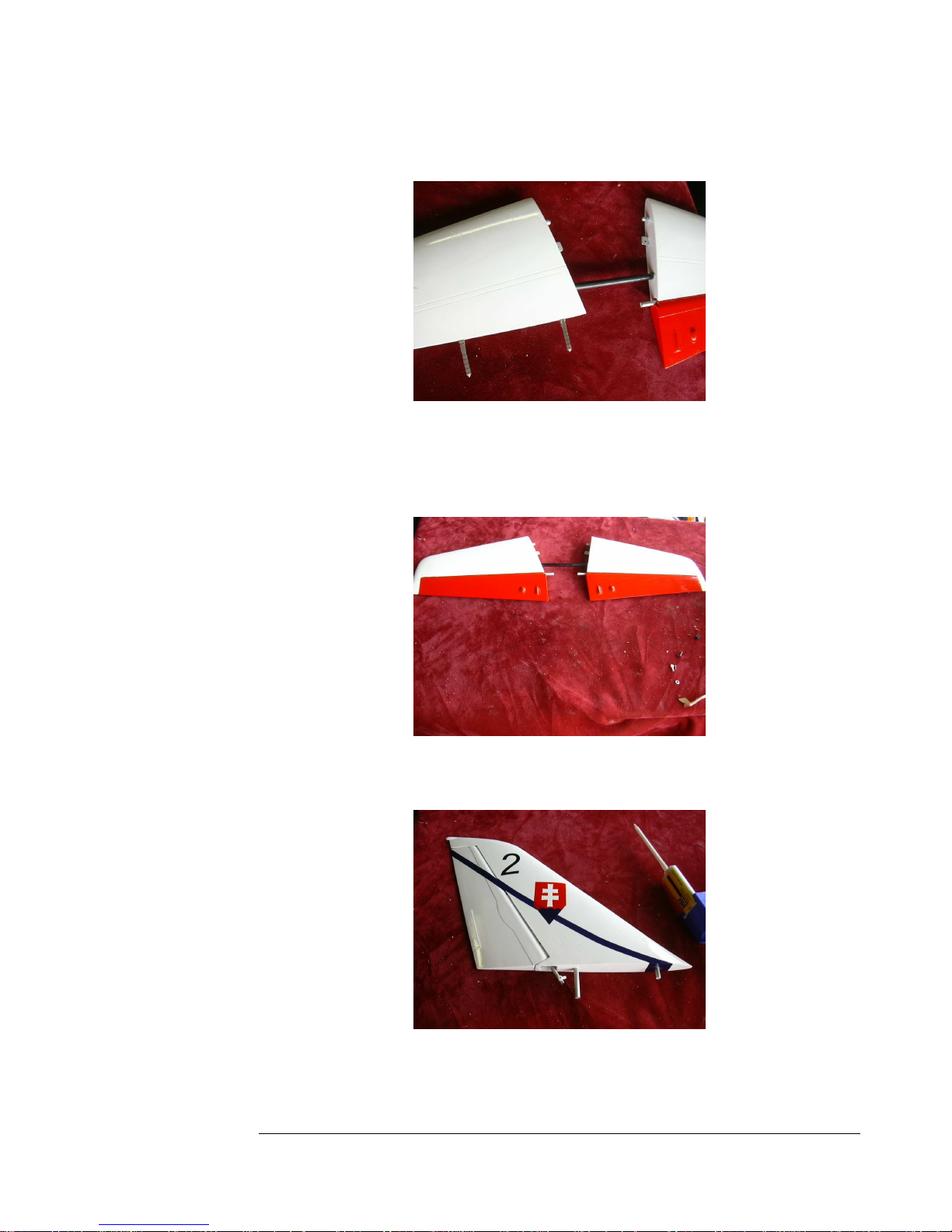
8. Insert the spar into the other stab and glue the hinges into that stab.
Figure 8
9. Add glue to the other elevator and press into place. Set aside to dry. Note
the importance of vaseline on the spar, and that the spar must be in place
before the hinges are glued.
Figure 9
10. Follow all the same procedures to hinge the rudder.
Figure 10
Page 9
F E I B A O L - 3 9 A L B A T R O S
9999
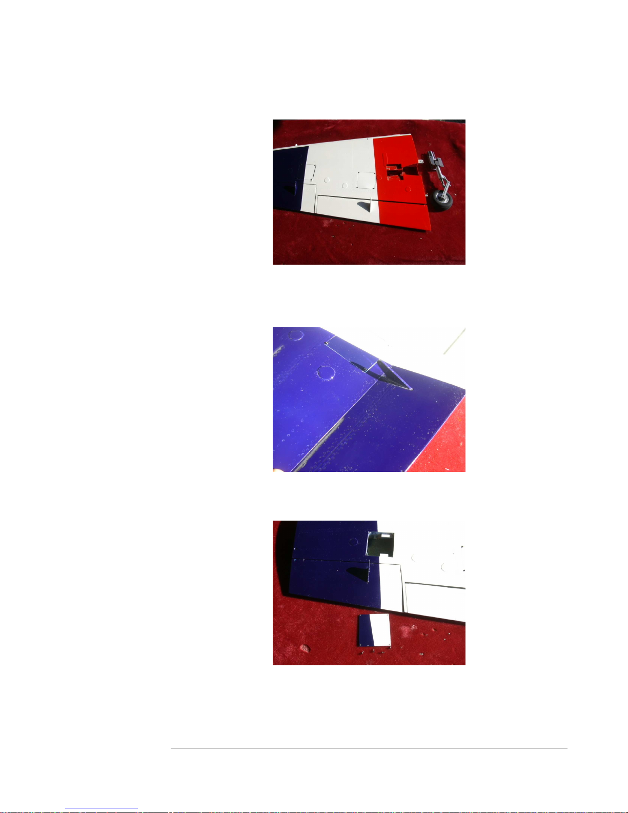
11. Remove the retract units from the wings and set them aside.
Figure 11
12. Check each hinge line for free movement. Sand the trailing edge of the
wing if needed to make an adequate gap between the bottom skins.
Figure 12
13. Remove the aileron servo cover and set it and its screws aside
Figure 13
Page 10
F E I B A O L - 3 9 A L B A T R O S
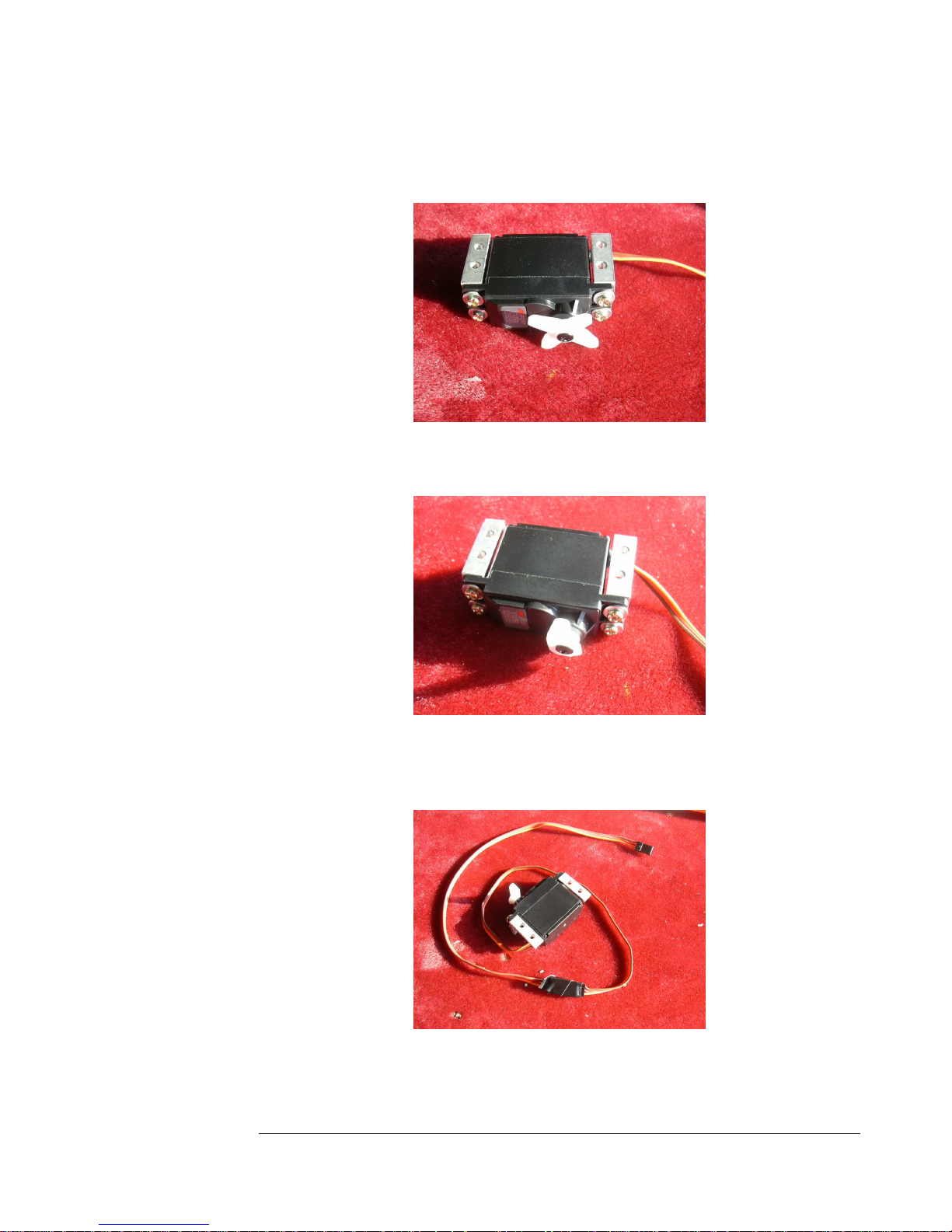
14. Secure mounts to the aileron servo as shown. Do not use servo
grommets.
Figure 14
15. Center the servo and prepare the servo horn as shown.
Figure 15
16. Add a twelve-inch extension to the servo and tape the connection for
security.
Figure 16
10
10
1010
Page 11
F E I B A O L - 3 9 A L B A T R O S
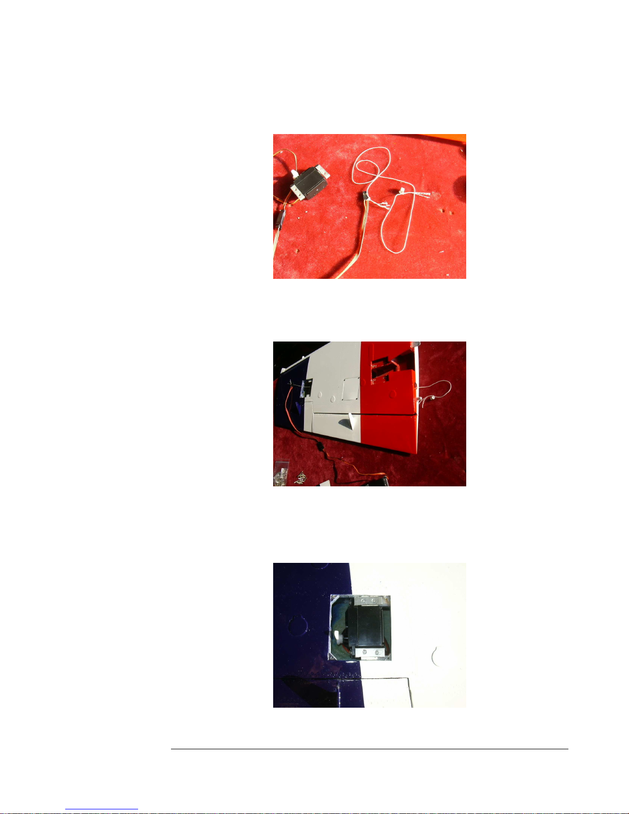
17. Tie a wheel collar or other weight to a piece of string and tie the string to
the aileron servo extension.
Figure 17
18. Drop the wheel collar in from the servo bay through the wing and out
the hole in the root rib as shown and pull the servo extension through.
Figure 18
19. Push the servo into place on the wooden mounts and carefully check
alignment.
Figure 19
11
11
1111
Page 12
F E I B A O L - 3 9 A L B A T R O S
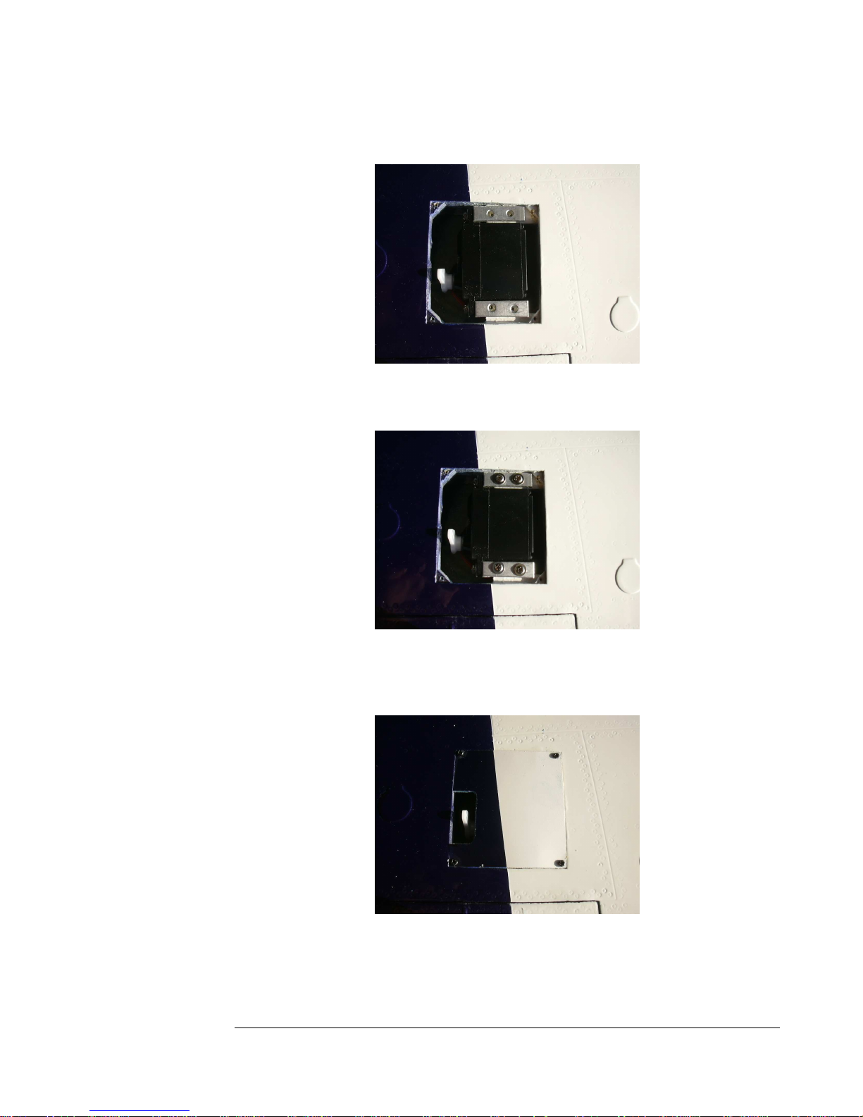
20. Drill four pilot holes for the mounting screws.
Figure 20
21. Secure the servo with four provided screws.
Figure 21
22. Cut a notch in the servo door for the servo horn and screw the door
back into place.
Figure 22
12
12
1212
Page 13
F E I B A O L - 3 9 A L B A T R O S
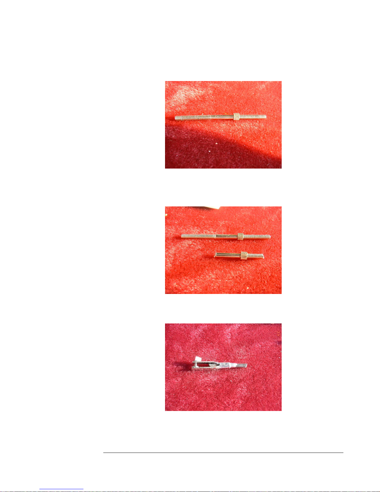
23. You will need to shorten the provided links. Start by dissasembling the
links, leaving a locking collar at one end.
Figure 23
24. Cut down the rod as shown in the bottom of the picture. Bevel the
threaded end and then unscrew the locking collar to clean up the threads.
Figure 24
25. Solder a clevis onto the other end of the rod as shown.
Figure 25
13
13
1313
Page 14
F E I B A O L - 3 9 A L B A T R O S
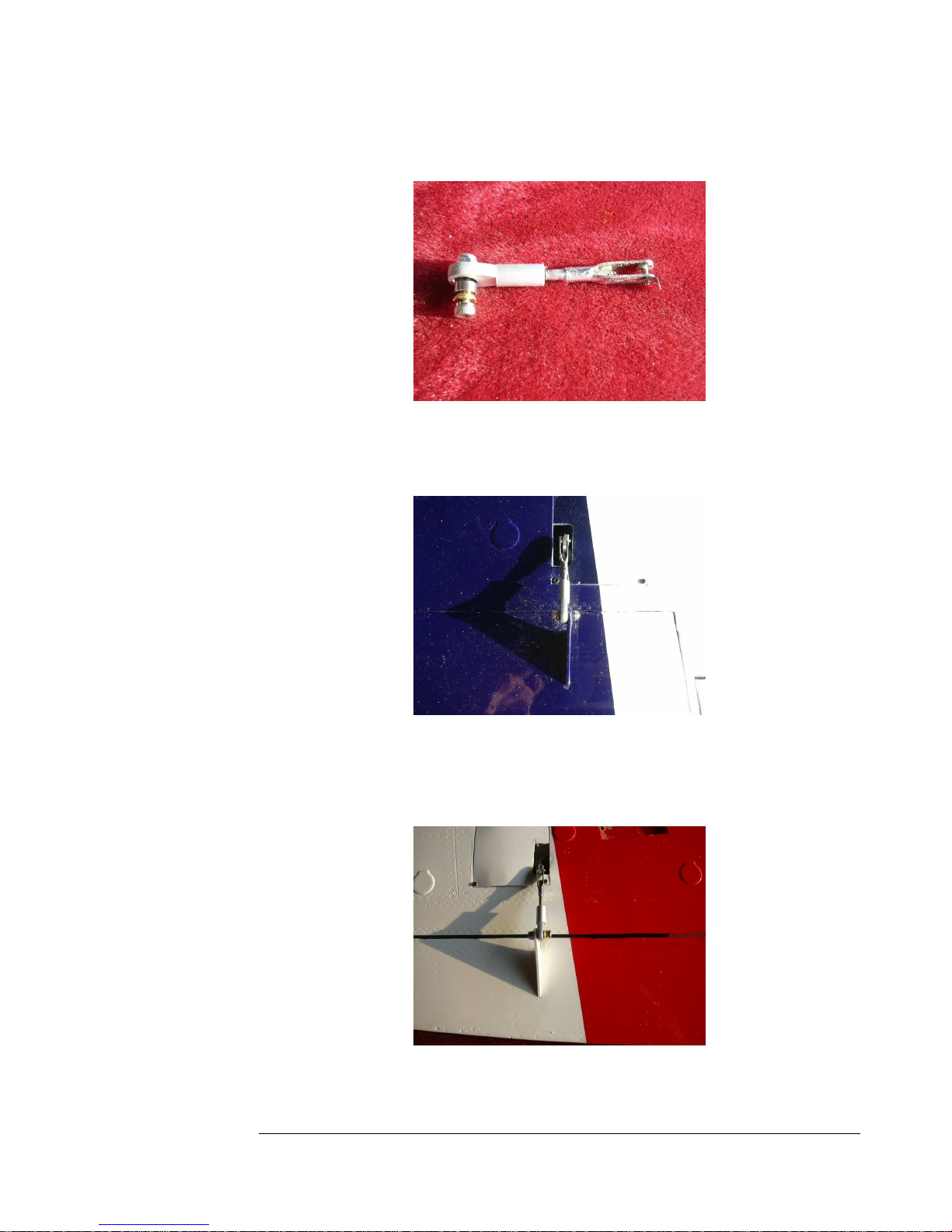
26. Add a bolt-on link to the other end as shown.
Figure 26
27. Install the new shortened linkage as shown. You will need to properly
size the hole in the surface control horn for the bolt.
Figure 27
28.
The flap servos are assembled in the same way, but note that the servo
needs to be all the way at one end of travel when the flap is neutral, and that
servo extensions are not needed
.
Figure 28
14
14
1414
Page 15
F E I B A O L - 3 9 A L B A T R O S
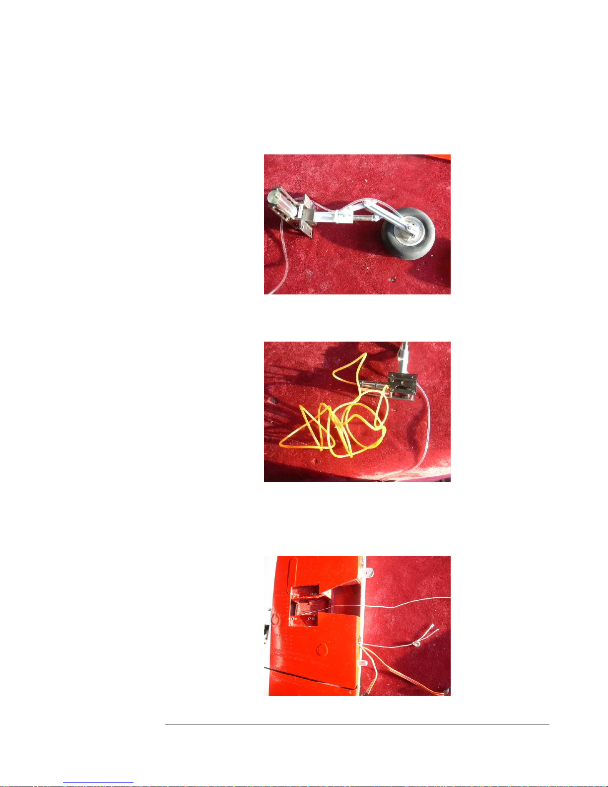
29. Use hemostats to install one end of the clear tubing roll to the brake
nipple. Secure the brake line to the strut also, using a tie wrap.
Figure 29
30. Install both ends of the colored tubing to both nipples of the retract unit.
Figure 30
31. Drop the wheel collar and string in through the retract bay to the flap
servo bay and then down out of the wing through the same hole the
servo extensions go through.
15
1515
15
Page 16
F E I B A O L - 3 9 A L B A T R O S
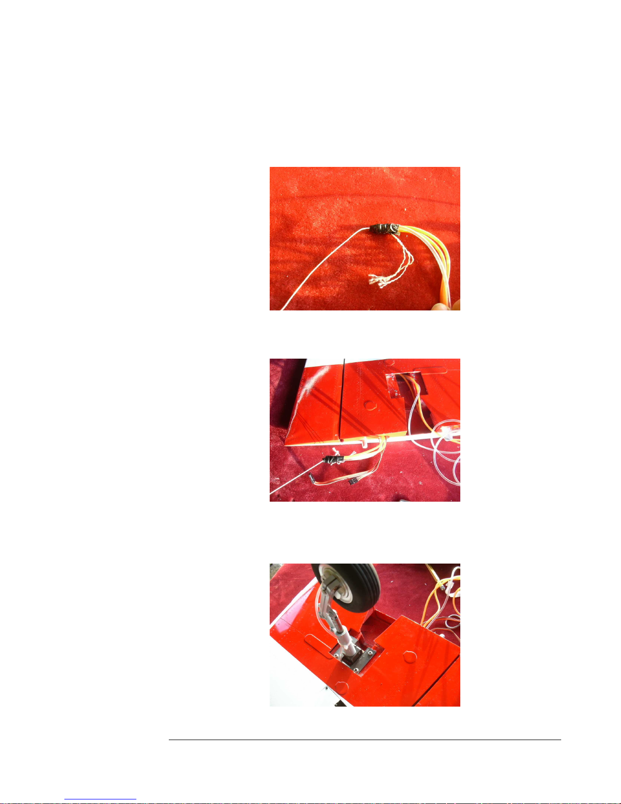
Figure 31
32. Tie the end of the string to the middle of the colored tubing going to the
retracts, then tape the end of the brake line tubing to the colored tubing
as shown.
Figure 32
33. Pull the airlines through the wing. Be very careful not to kink the tubing.
Figure 33
34. Install the retract unit with four screws. Again, pay close attention not to
pinch or kink any tubing.
16
1616
16
Page 17
F E I B A O L - 3 9 A L B A T R O S
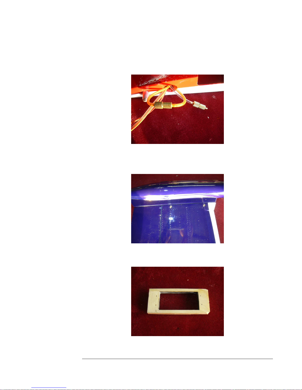
Figure 34
35. Cut off all three air lines about three inches from the root. Install a quick
disconnect between the two retract lines, and one to the brake line.
Figure 35
36. Install the tip tank with the provided screws. Repeat all the procedures
for the other side, and the wings are complete.
Figure 36
37. Construct a servo tray for the rudder
Figure 37
17
17
1717
Page 18
F E I B A O L - 3 9 A L B A T R O S
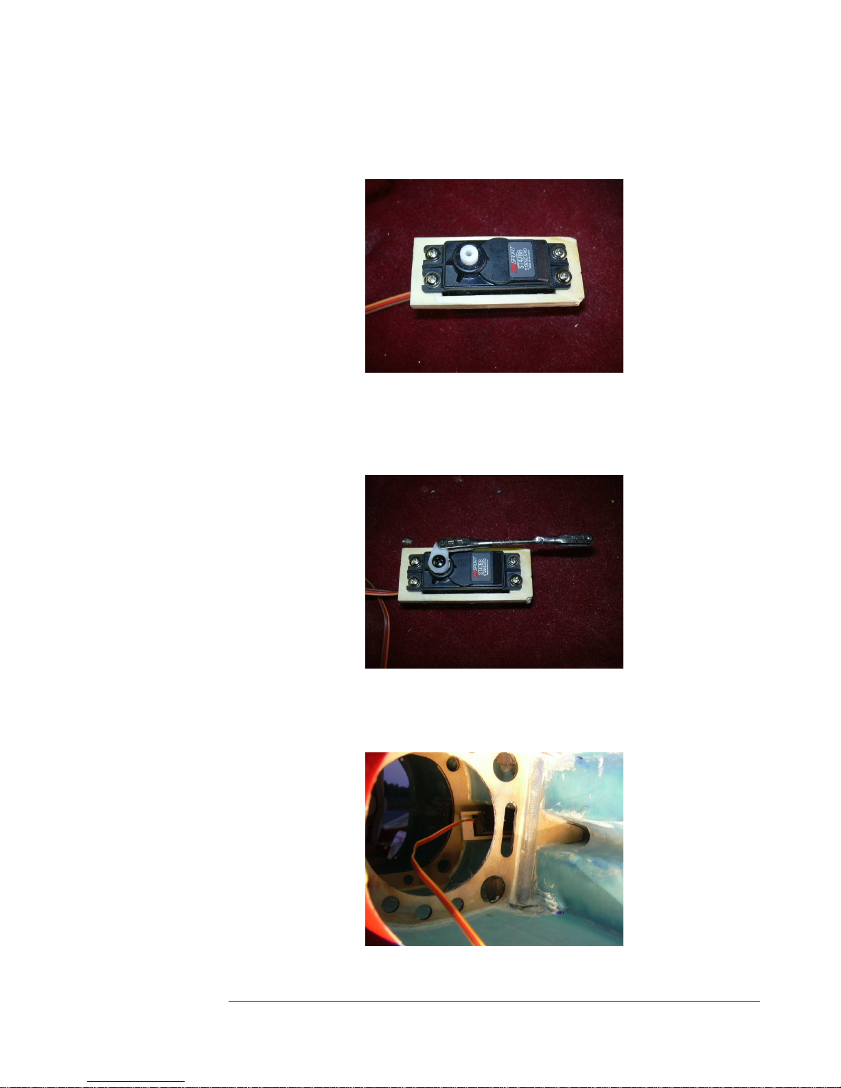
38. Install the rudder servo to the tray using the provided screws. Do not use
grommets.
Figure 38
39. Shorten a link as shown and solder a clevis to it. Make a servo horn using
the innermost hole on the horn. Neutralize the servo and install the horn
and link.
Figure 39
40. Slip the servo assembly into the fuselage, with the linkage pointing out
the square hole in the fin mount.
Figure 40
18
18
1818
Page 19
F E I B A O L - 3 9 A L B A T R O S
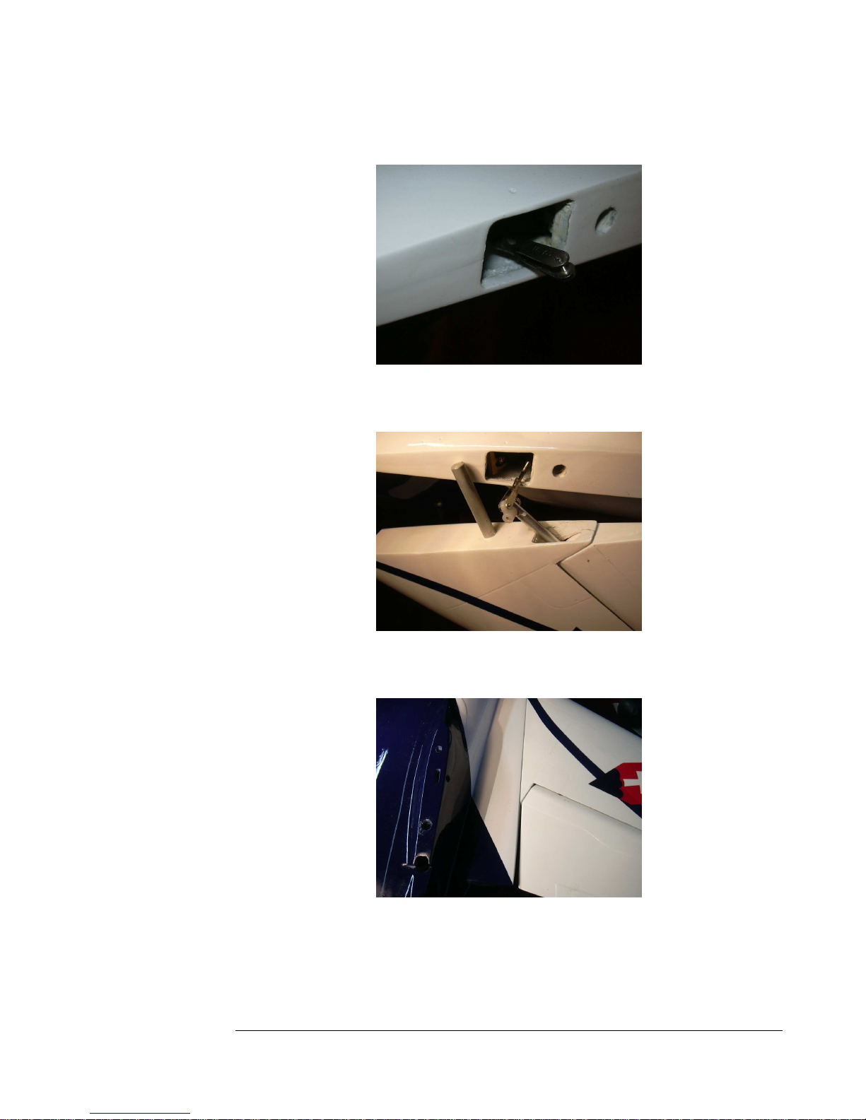
41. The linkage needs to stick out the hole as shown2.
Figure 41
42. Connect the linkage to the rudder horn as shown. Use a safety clip also.
Figure 42
43. Insert the rudder and fin into place.
Figure 43
19
19
1919
Page 20
F E I B A O L - 3 9 A L B A T R O S
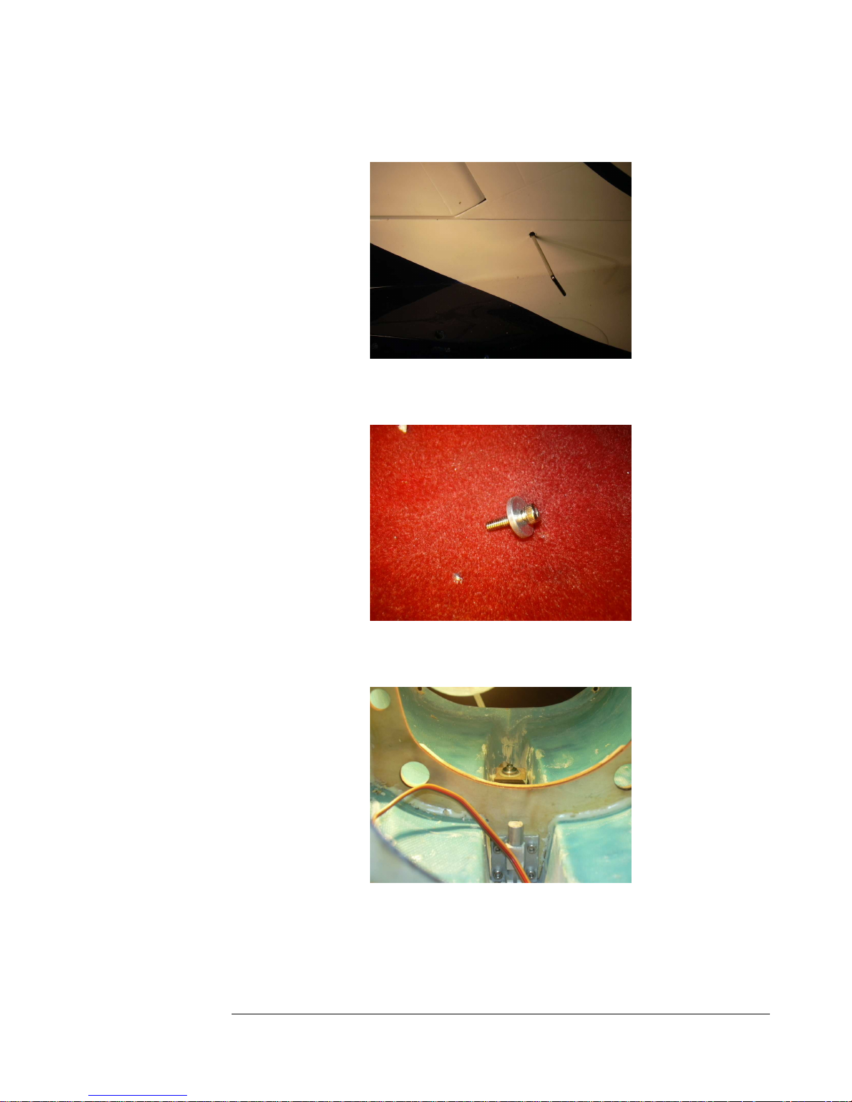
44. Tighten the fin retaining clamp using the supplied wrench.
Figure 44
45. Locate this provided bolt and large washer.
Figure 45
46. Tighten the bolt and washer into place inside the fuselage as shown.
Figure 46
20
20
2020
Page 21
F E I B A O L - 3 9 A L B A T R O S
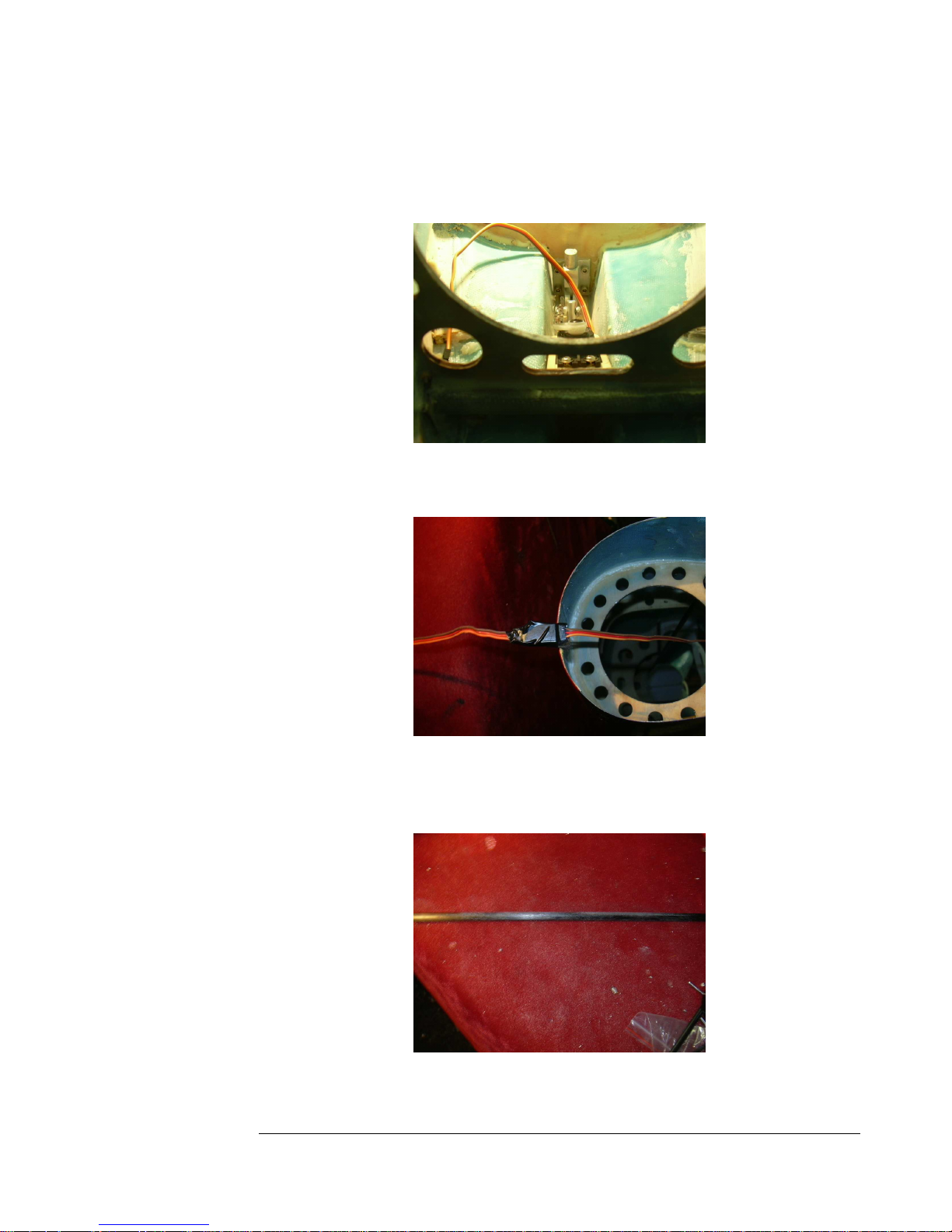
47. Slide the rudder servo back and forth and adjust the linkage until the
rudder is neutral and you are happy with the action. Hysol the servo tray
into place.
Figure 47
48. Add a thirty-six inch extension to the rudder servo, tape it for security.
Figure 48
49. Clean the carbon fiber spar rod thoroughly, and then rough it up with
sandpaper.
Figure 49
21
21
2121
Page 22
F E I B A O L - 3 9 A L B A T R O S
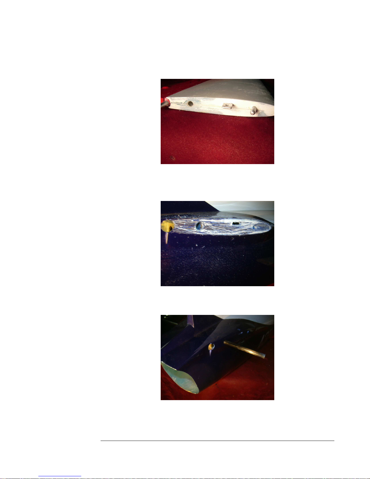
50. Roughen up the stab roots and remove the paint to expose the fiberglass
underneath.
Figure 50
51. Roughen up the stab mounts on the fuse the same way. You may also
drill small holes in both parts to give the glue a better grip, too.
Figure 51
52. Coat the center of the stab spar with hysol and insert it into the fuse.
Figure 52
22
22
2222
Page 23
F E I B A O L - 3 9 A L B A T R O S
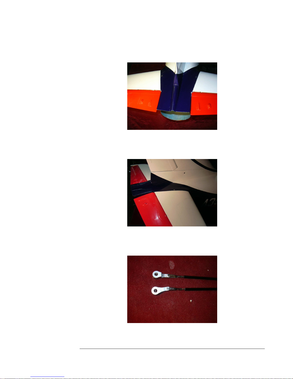
53. Hysol the stabs into place. Be sure to use adequate glue, both on the
roots and the spar.
Figure 53
54. Secure the stabs with the two provided bolts. Check alignment throughly
while drying.
Figure 54
55. Attach the elevator horns to the provided fiberlgass elevator pushrods as
shown.
Figure 55
23
23
2323
Page 24
F E I B A O L - 3 9 A L B A T R O S
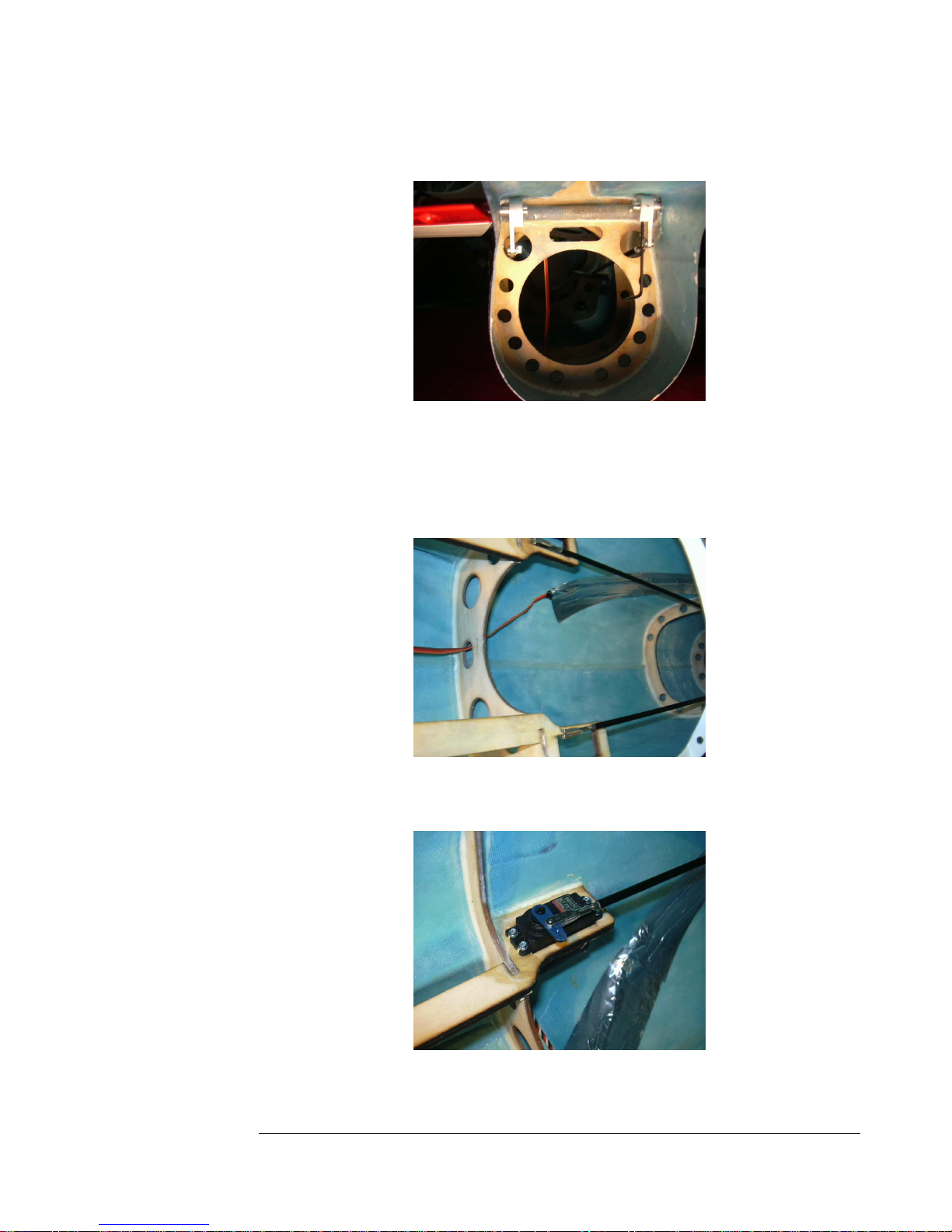
56. Install the pushrods and secure them using the provided allen wrench.
Figure 56
57. Use aluminum tape to secure the rudder servo extension to the top and
side of the fuselage, it must not hang and touch the hot tailpipe. Coil up
the elevator and rudder extensions and tempo
Figure 57
58.
Ins
tall the elevator servos and connect them the servo extensions.
Figure 58
24
24
2424
Page 25
F E I B A O L - 3 9 A L B A T R O S
59. Remove the radio trays from the nose of the fuse. Paint them if you like,
and set them aside for later.
Figure 59
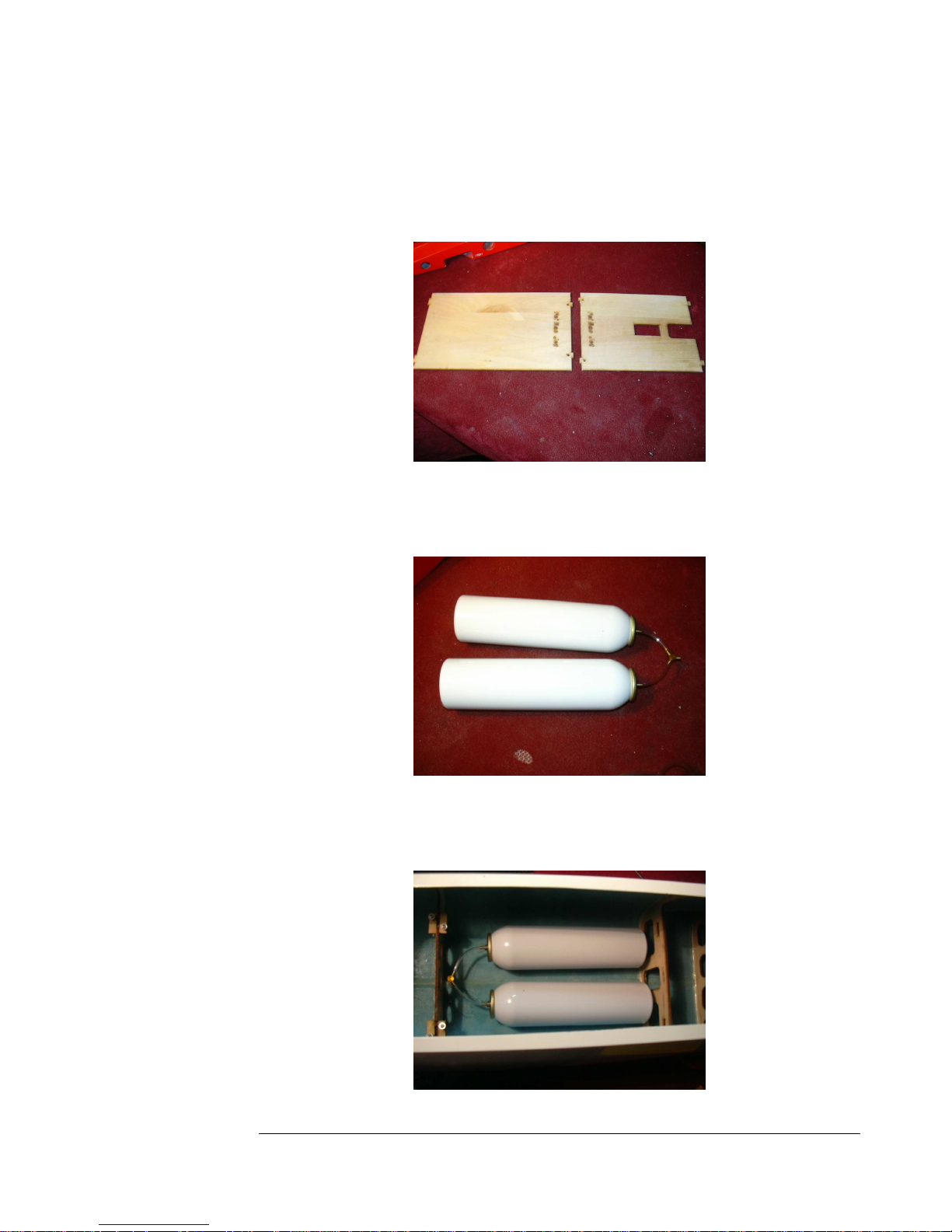
60. Link the two air bottles together with a short section of tubing. Cut the
tubing in the middle and install a y-connector.
Figure 60
61. Install the air tanks with silicone to the floor beneath the rear radio tray.
Leave a one-inch gap between the two tanks for wiring to run through.
25
2525
25
Page 26
F E I B A O L - 3 9 A L B A T R O S
62. Remove the nose gear unit.
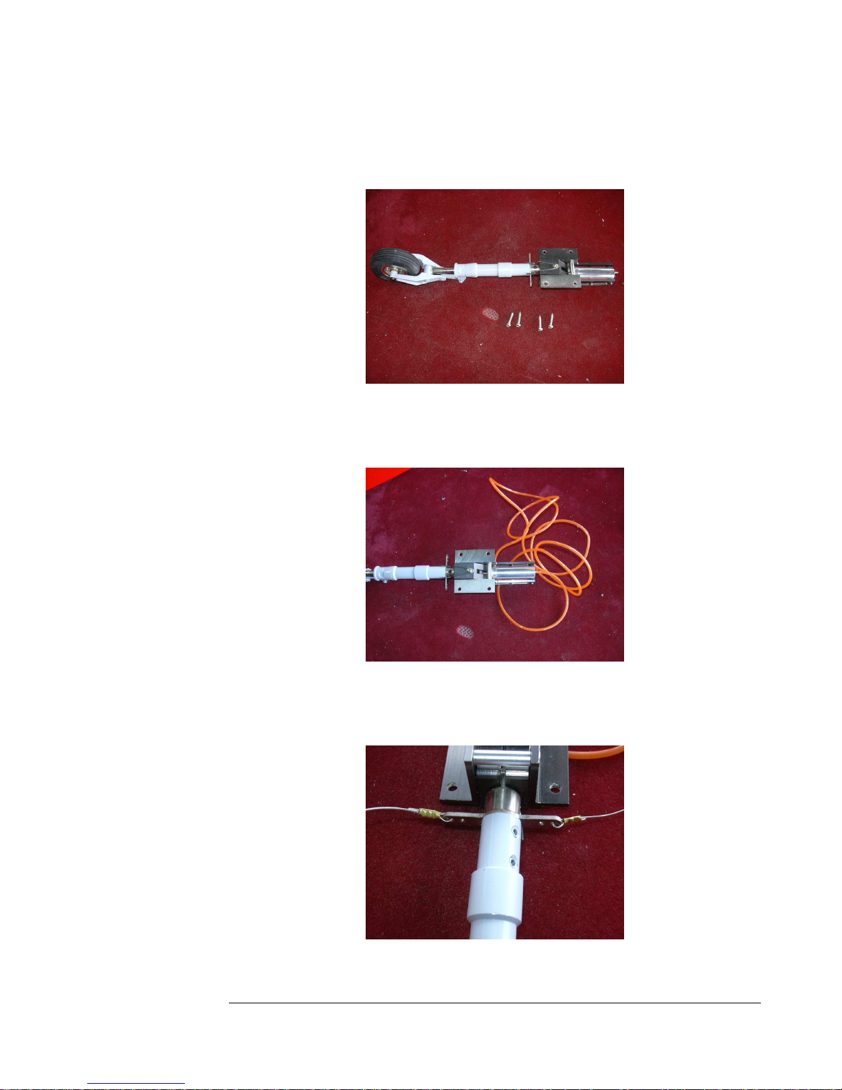
Figure 61
Figure 62
63. Attach a section of tubing about 18 inches long to the nipples of the nose
gear retract unit.
Figure 63
64. Crimp the ends of the steering cable to the outer holes on the nose gear
steering arm, then cut the cable in half to make two separate pieces.
Figure 64
26
26
2626
Page 27
F E I B A O L - 3 9 A L B A T R O S
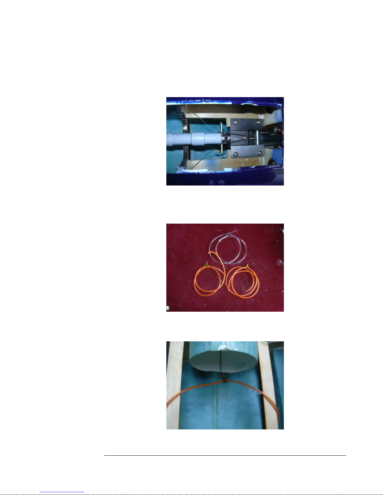
65. Reinstall the nose gear unit and feed the steering cables through the
white plastic tubes. Hemostats are handy for this.
Figure 65
66. Make up three lengths of tubing about 18 inches long. Divide each into
half and add a y connector to each.
Figure 66
67. Run the airlines bellow the intakes.
Figure 67
27
27
2727
Page 28
F E I B A O L - 3 9 A L B A T R O S
68. Feed the three long lines forward through the bulkhead in front of the
main wheel wells.
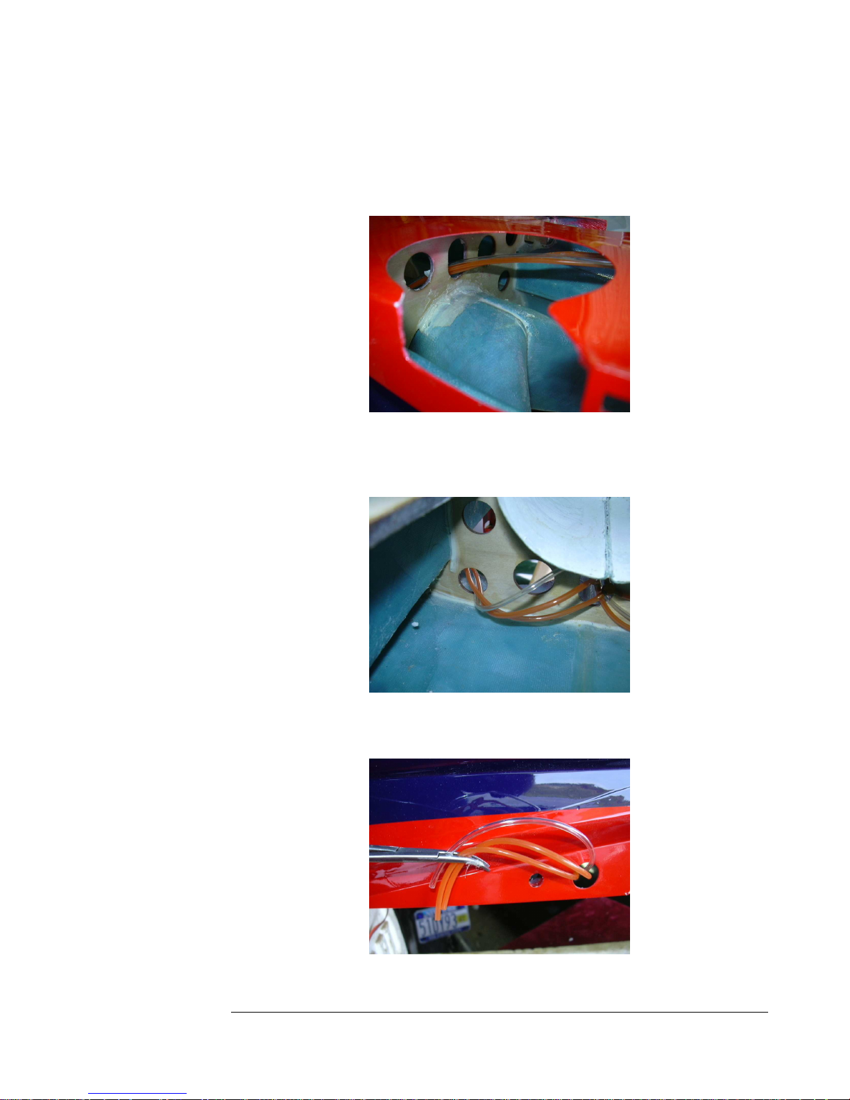
Figure 68
69. Feed one side of each teed off section through the holes on each side of
the bulkhead behind the wheel wells.
Figure 69
70. Pull the lines out through the holes in the wing roots.
Figure 70
28
28
2828
Page 29
F E I B A O L - 3 9 A L B A T R O S
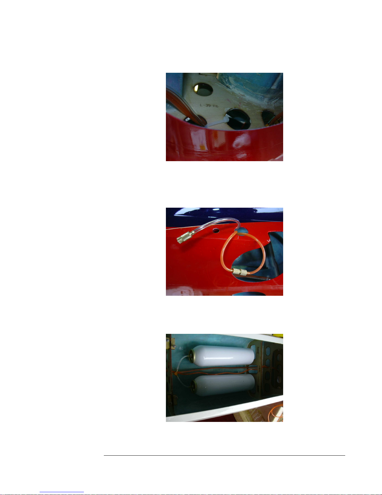
71. Secure the lines to the bulkhead on each side with tie wraps as shown.
Figure 71
72. Cut off any excess line, leaving about three inches, and add one complete
air disconnect to the pair of retract lines and half of one to the brake line
on each side.
Figure 72
73. Run all the long lines forward to the nose section. They go under the
main spar tube and through all the holes in the bulkheads, and between
the air tanks.
Figure 73
29
29
2929
Page 30
F E I B A O L - 3 9 A L B A T R O S
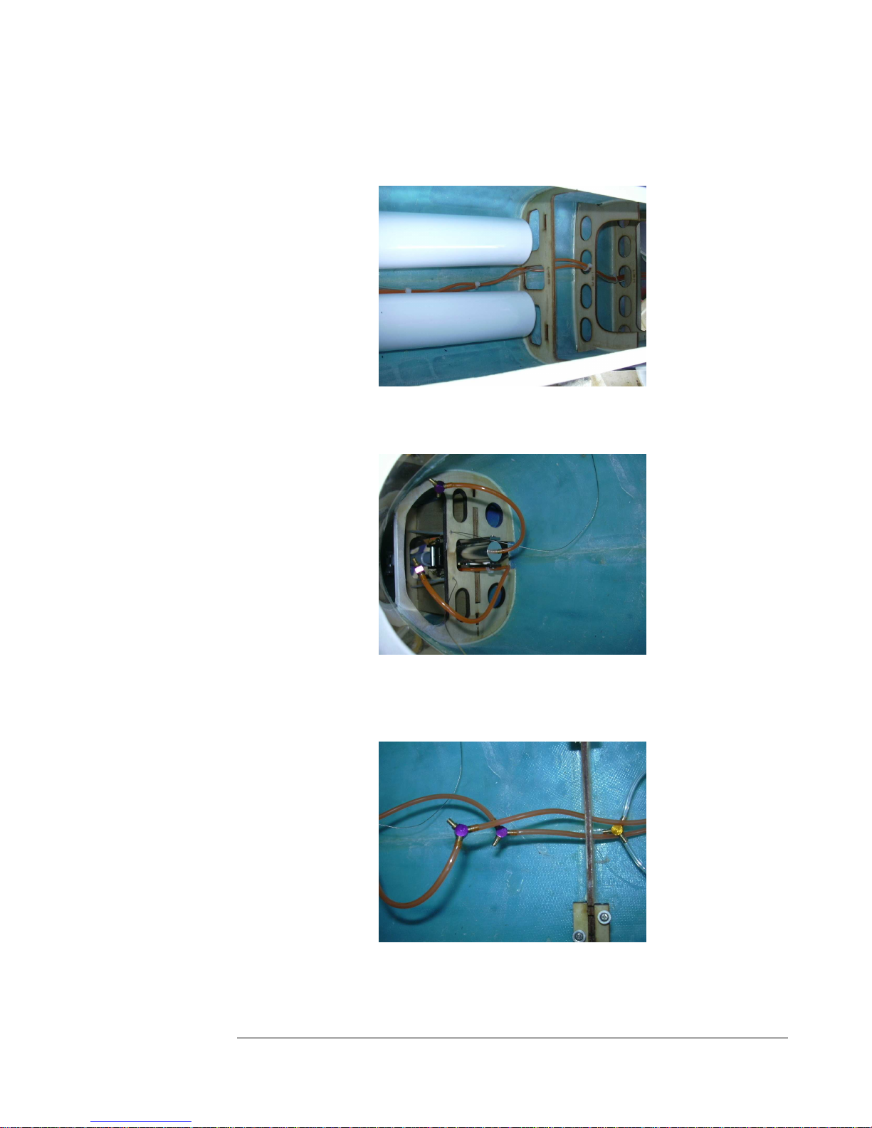
74. Bundle the three lines together with tie wraps for neatness. Do not pinch
the lines with the tie wraps.
Figure 74
75. Add a y connector to each of the two lines from the nose gear retract.
Figure 75
76. Cut off any excess tubing and connect the two retract lines from the rear
to the ones from the nose gear.
Figure 76
30
30
3030
Page 31
F E I B A O L - 3 9 A L B A T R O S
77. Leave the brake line long for now and tape it out of the way to the
bottom of the fuse in the nose.
Figure 77
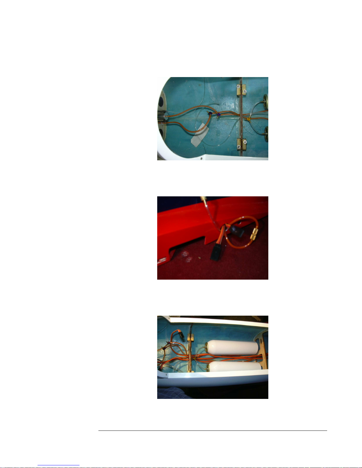
78. Add two 36-inch extensions to each side, starting at the wing root, for
the flaps and ailerons.
Figure 78
79. Route these extensions forward, following the exact same path as the
airlines. Do the same for the elevator and rudder extensions.
Figure 79
31
31
3131
Page 32
F E I B A O L - 3 9 A L B A T R O S
80. Bundle all the extensions together with tie wraps.
Figure 80
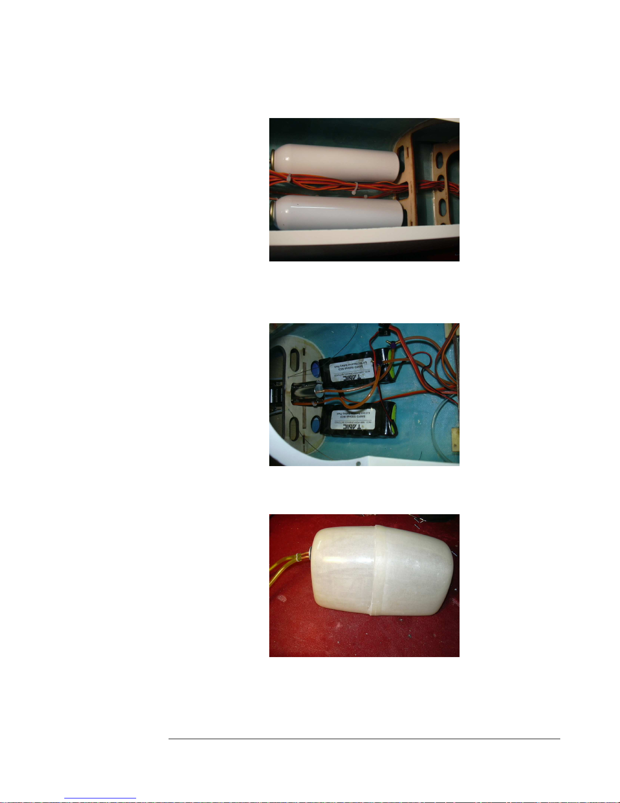
81. Silicone your receiver batteries as far forward as far forward as you can
get to the floor of the front radio compartment.
Figure 81
82. Check you fuel tank for likings before installation.
Figure 82
32
32
3232
Page 33
F E I B A O L - 3 9 A L B A T R O S
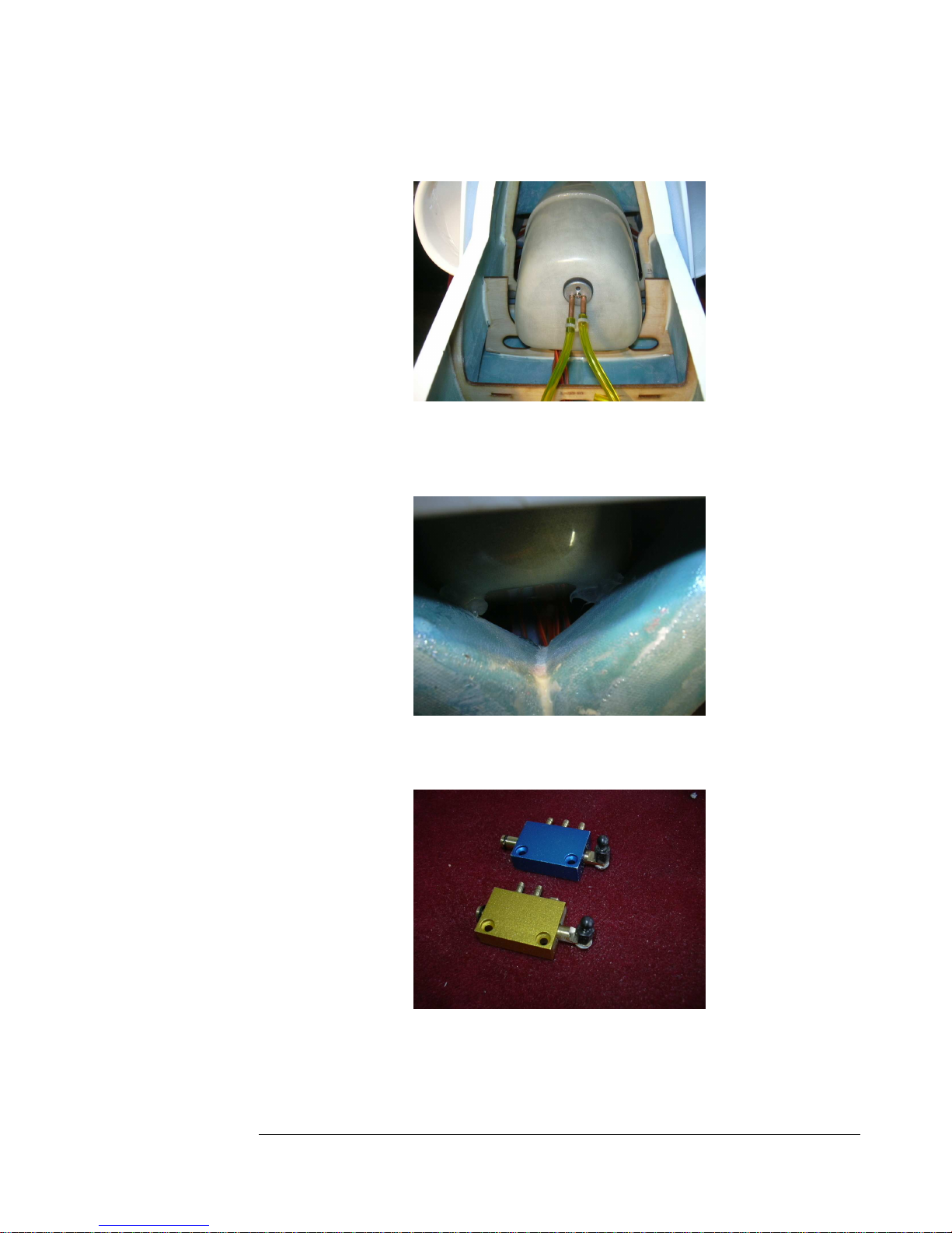
83. Glue the tank into place with silicone.
Figure 83
84. The tank should touch the intakes and be glued with a little silicone
there, too.
Figure 84
85. Add a ball link to each of the air valves.
Figure 85
33
33
3333
Page 34
F E I B A O L - 3 9 A L B A T R O S
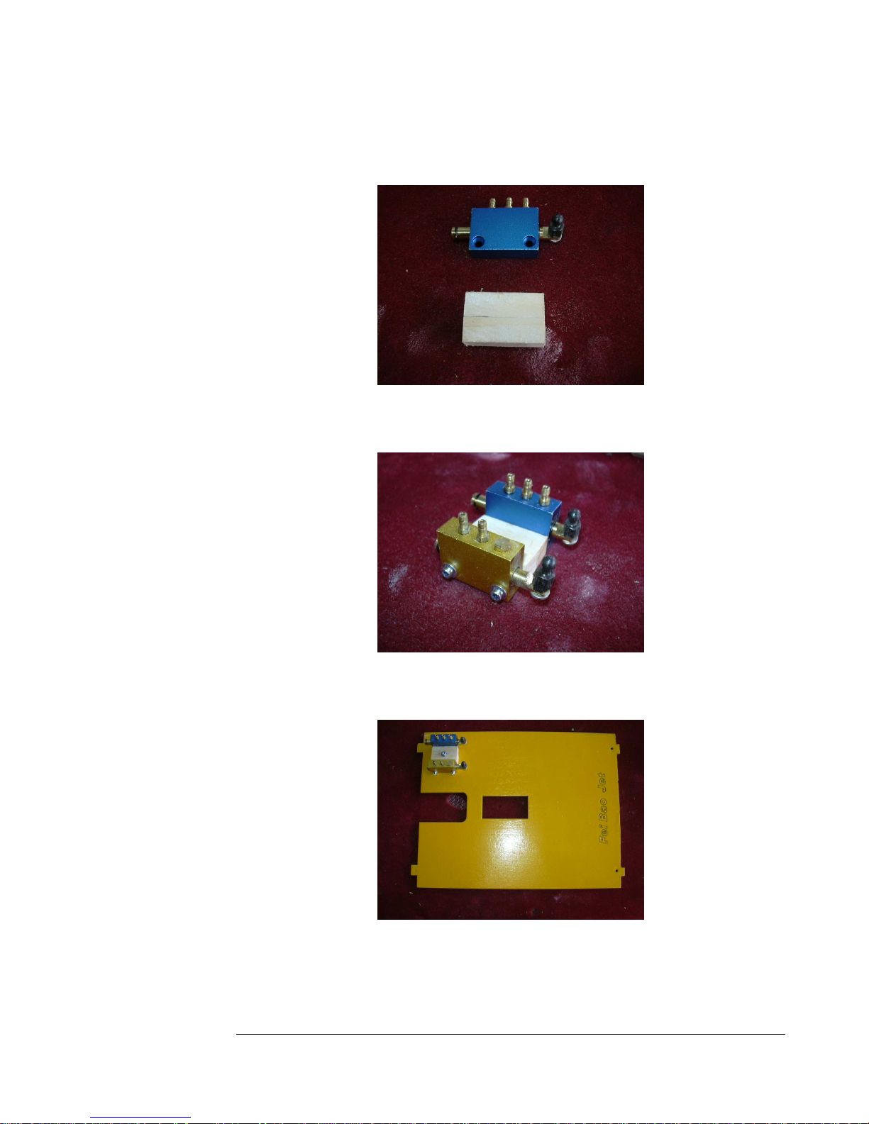
86. Make up a hardwood block to mount the valves to. It should be about
the size of one of the valves
Figure 86
87. Screw the valves to the block.
Figure 87
88. Screw and glue the valve assembly to the forward radio tray.
Figure 88
34
34
3434
Page 35
F E I B A O L - 3 9 A L B A T R O S
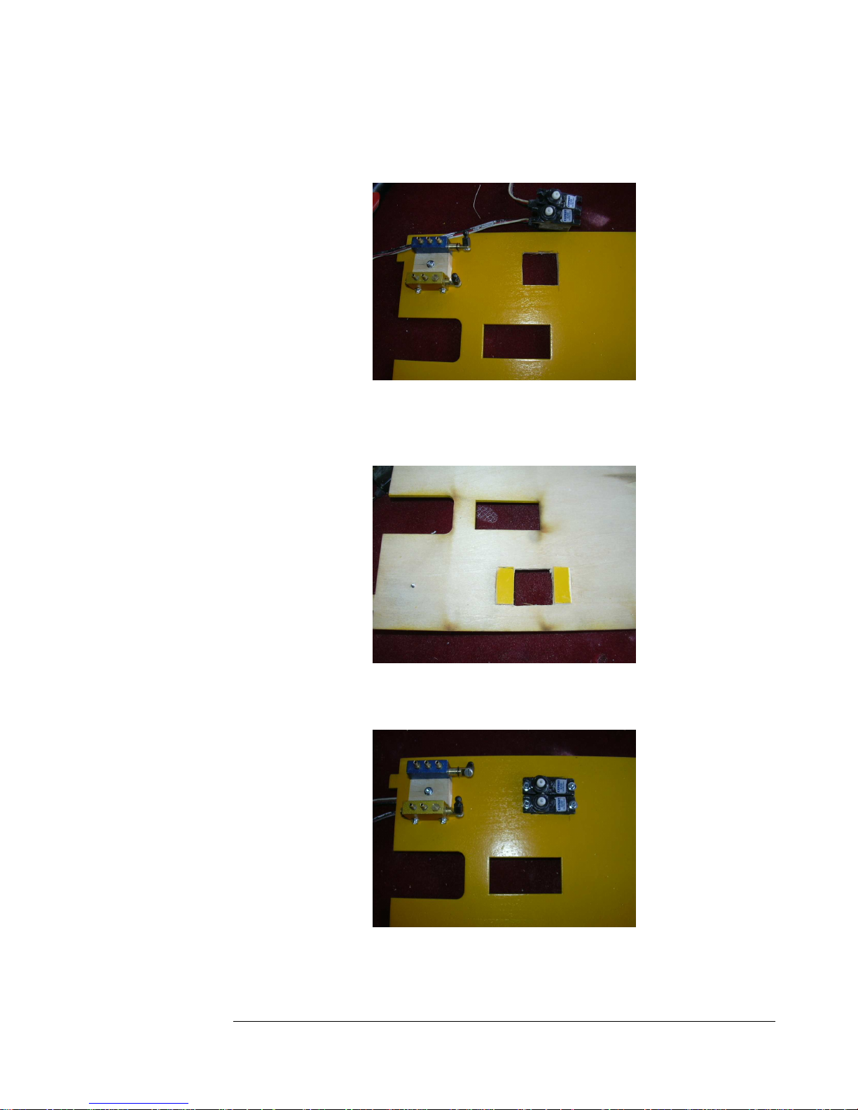
89. Cut out a hole big enough to just accommodate two mini servos for the
valves.
Figure 89
90. Cut the scrap you just removed in two and glue it on the bottom of the
tray for reinforcement for the servo mounting screws.
Figure 90
91. Install the two servos.
Figure 91
35
35
3535
Page 36
F E I B A O L - 3 9 A L B A T R O S
92. Add ball links to the servos.
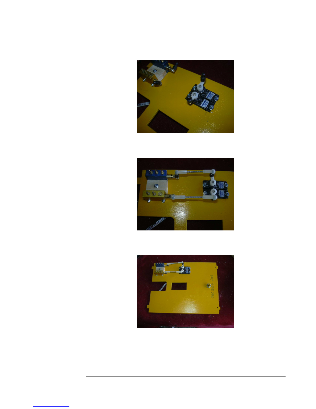
Figure 92
93. Connect the servos and valves with linkages.
Figure 93
94. Drill a hole and add the filler valve to the forward radio tray.
Figure 94
36
36
3636
Page 37
F E I B A O L - 3 9 A L B A T R O S
95. Test fit the tray and mark the clearance needed for the retract nipple on
the nose gear.
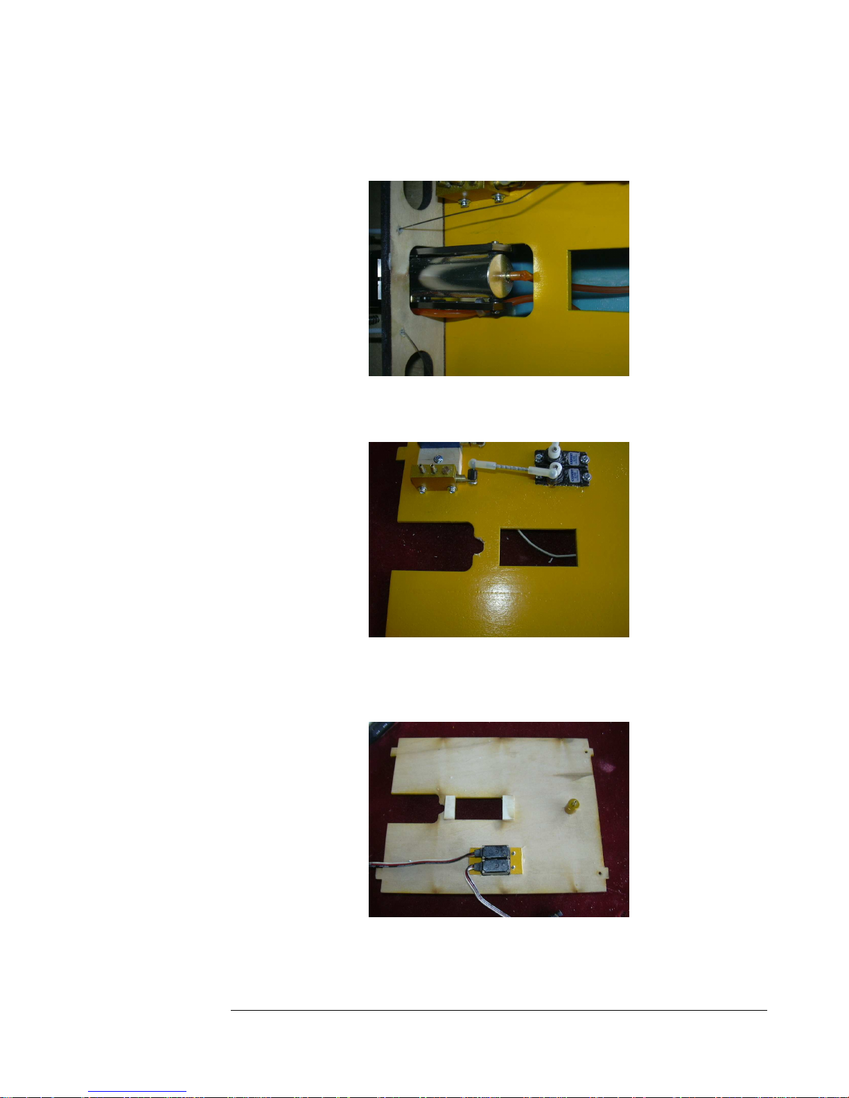
Figure 95
96. Cut a notch to make sure the nose gear line is not pinched.
Figure 96
97. Glue some pieces of scrap ply to the bottom of the tray for the nosegear
servo mounting screws.
Figure 97
37
37
3737
Page 38
F E I B A O L - 3 9 A L B A T R O S
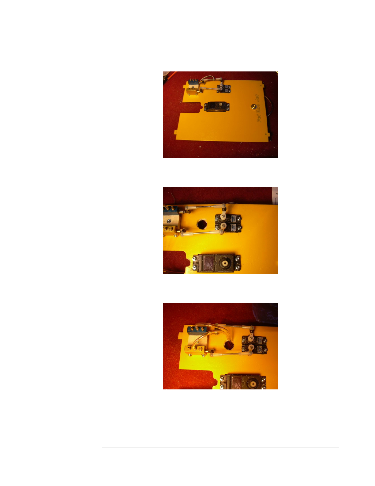
98. Mount the nose gear steering servo to the tray.
Figure 98
99. Drill a three quarter inch hole as shown for airlines.
Figure 99
100. Connect the two nipples shown with a six-inch section of airline
and feed the line down through the hole.
Figure 100
38
38
3838
Page 39
F E I B A O L - 3 9 A L B A T R O S
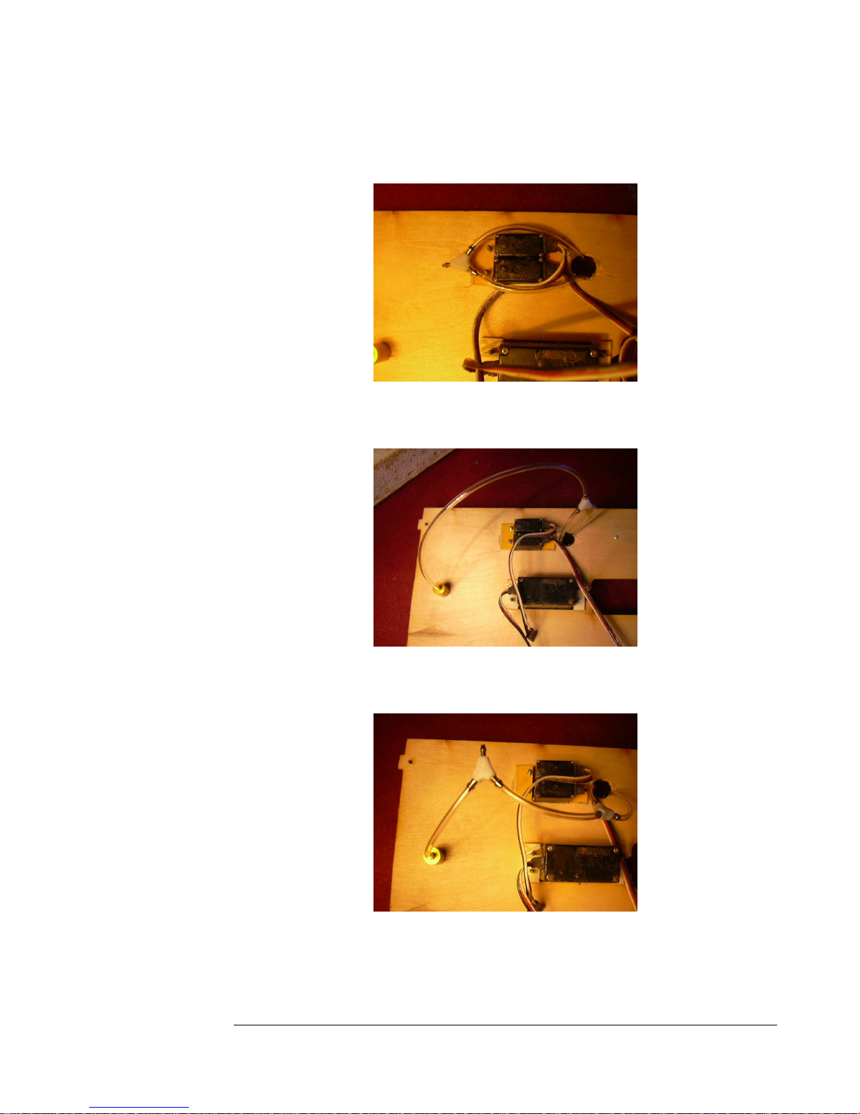
101. Cut that line in two and reconnect it with a y connector.
Figure 101
102. Add a short section of line to connect the y-connector to the fill
valve.
Figure 102
103. Cut that line in half and add a y-connector between.
104. Add another section of line about 9 inches long to the remaining
nipple of the connector.
Figure 103
39
39
3939
Page 40
F E I B A O L - 3 9 A L B A T R O S
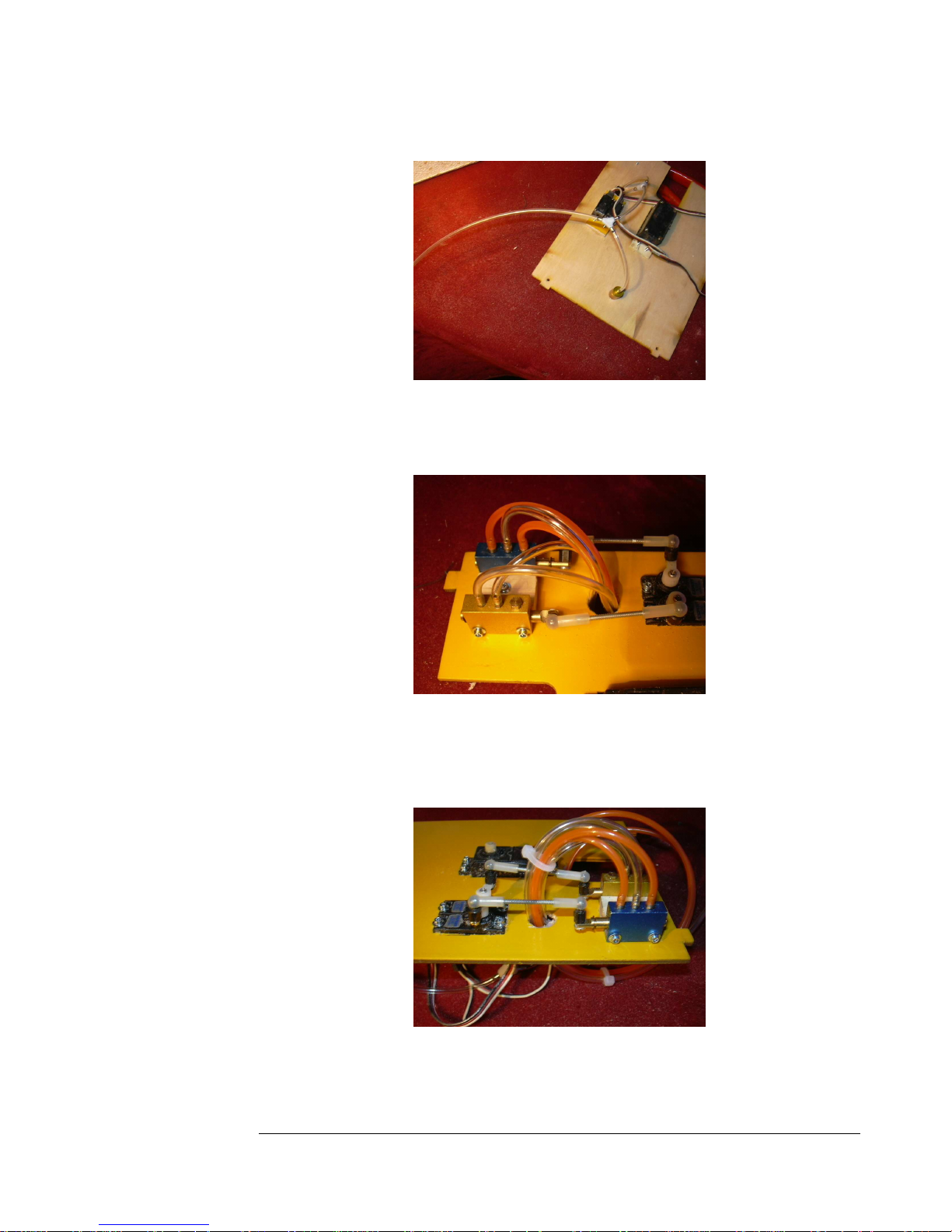
Figure 104
105. Add two sections of airline about 9 inches long to the remaining
nipples on the retract valve and run them out the hole.
Figure 105
106. Bundle these lines together with tie wraps for neatness.
Figure 106
40
40
4040
Page 41
F E I B A O L - 3 9 A L B A T R O S
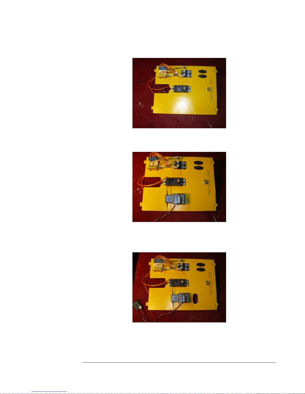
107. Add two high-quality switches.
Figure 107
108. Add your receiver.
Figure 108
109. Cut a slot in the tray for the servo leads to come up to the receiver
from beneath the tray.
Figure 109
41
41
4141
Page 42
F E I B A O L - 3 9 A L B A T R O S
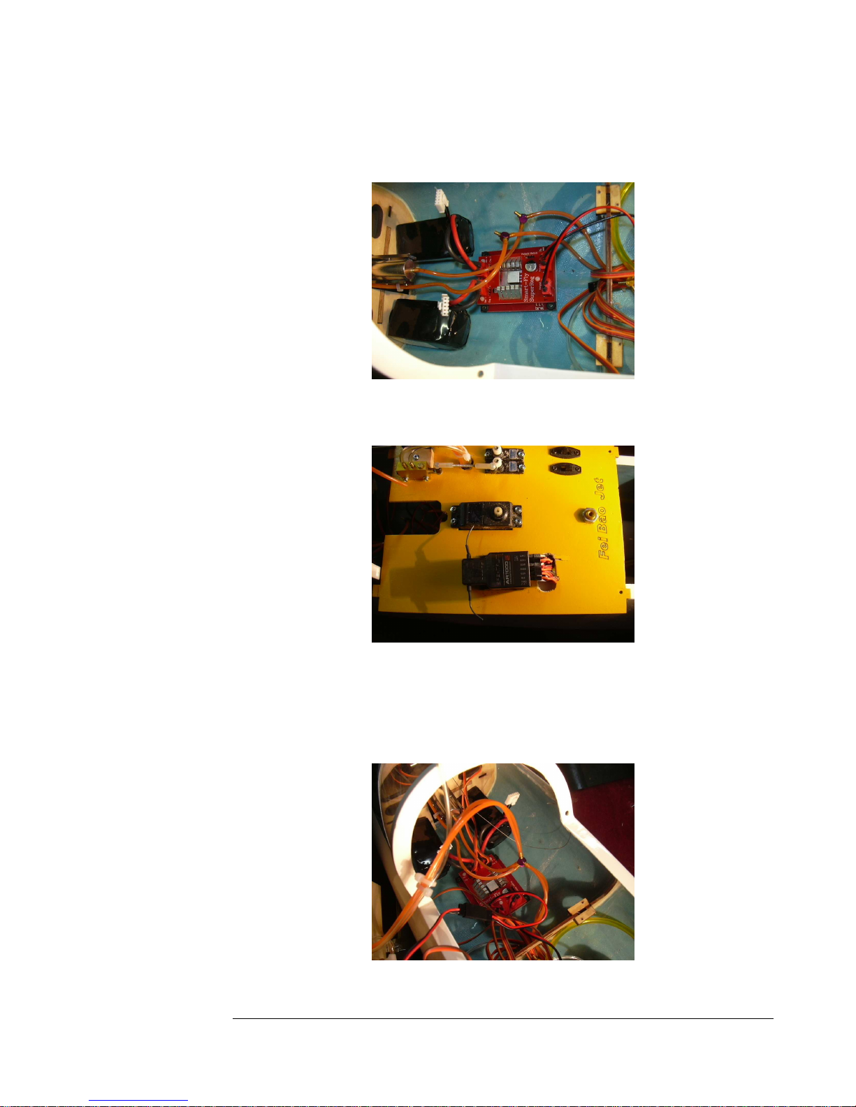
110. Add a regulator or powerbox if desired, behind the batteries on the
fuselage floor.
Figure 110
111. Connect the servo and battery leads to the receiver.
Figure 111
112. Connect the two retract lines from the valve to the y-connectors
you installed earlier connecting the front and rear retracts.
Figure 112
42
42
4242
Page 43
F E I B A O L - 3 9 A L B A T R O S
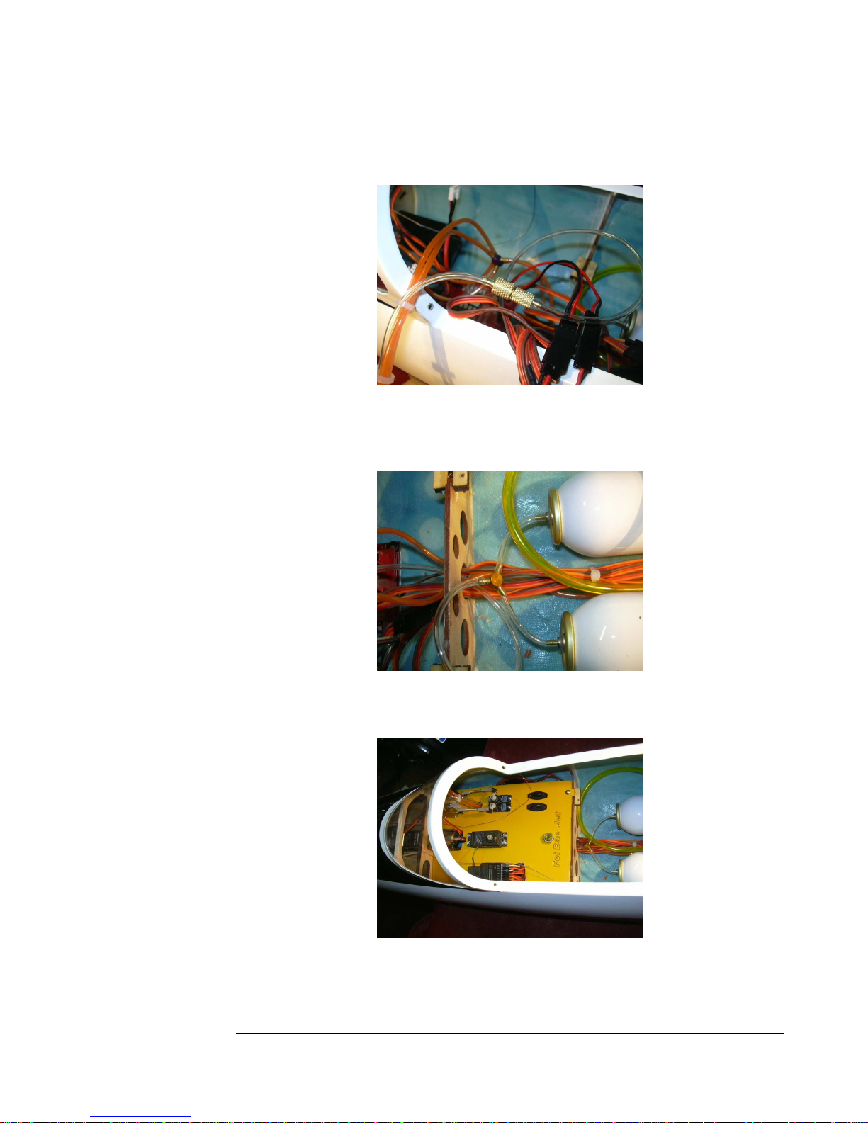
113. Connect the brake line to line coming from the brake valve. Use a
quick disconnect, or connect it directly to the valve.
Figure 113
114. Connect the air supply line from the radio tray to the y-connector
between the air tanks.
Figure 114
115. Place the radio tray into the fuse and secure with two screws.
Figure 115
43
43
4343
Page 44
F E I B A O L - 3 9 A L B A T R O S
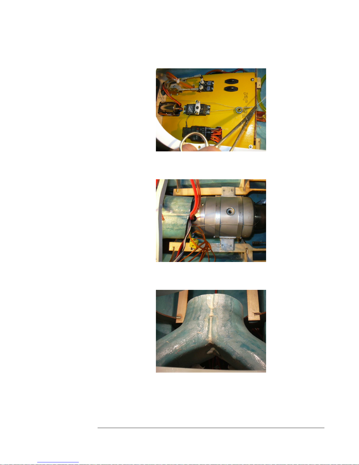
116. Install the nose gear steering wires to the servo arms.
Figure 116
117. Try to fit the turbine.
Figure 117
118. You should cut one inch of the intake to center the turbine.
Figure 118
44
44
4444
Page 45
F E I B A O L - 3 9 A L B A T R O S
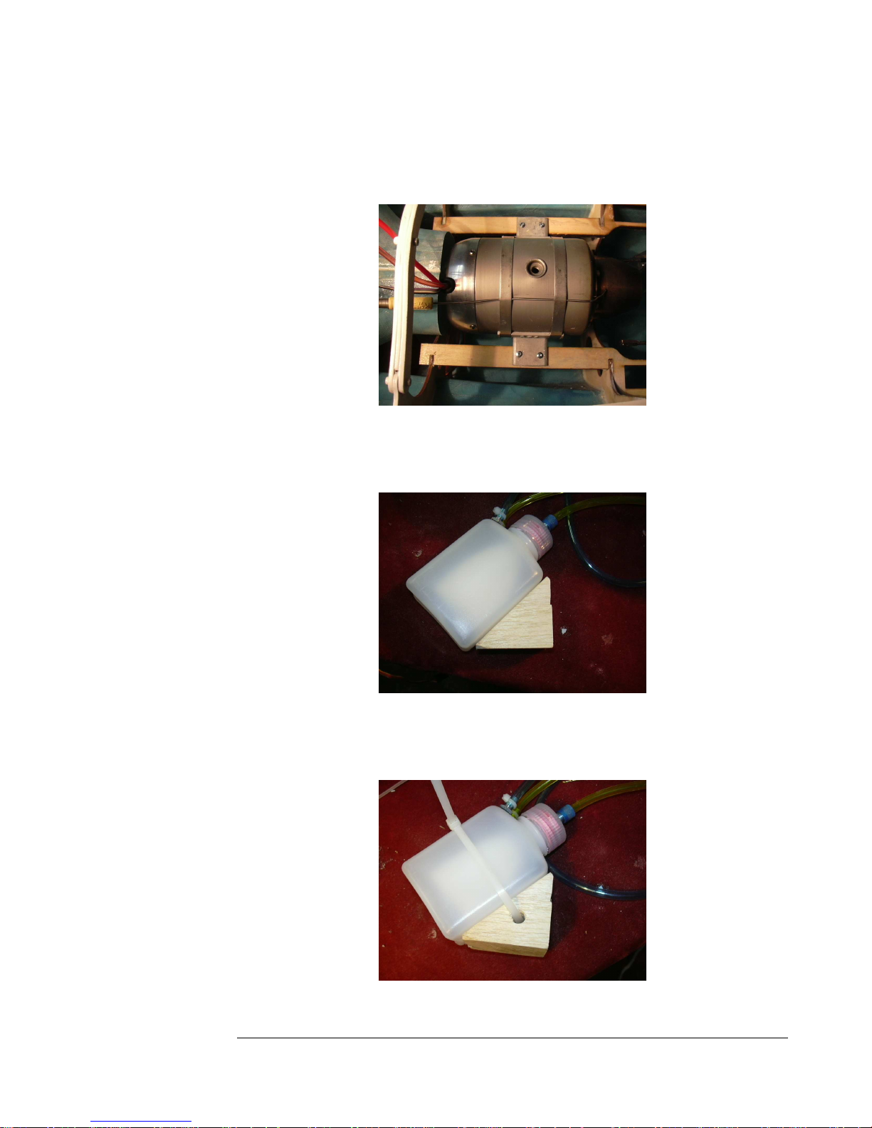
119. Carefully check the centering of the engine and screw into place.
You need to pay attention to the engine manufacturer's specified distance
between engine and pipe.
Figure 119
120. Plumb lines onto your UAT, then make up a balsa or hardwood
block as shown to mount the UAT.
Figure 120
121. Drill a hole in the block for a tie wrap...attach the tie wrap but do
not tighten yet.
Figure 121
45
45
4545
Page 46
F E I B A O L - 3 9 A L B A T R O S
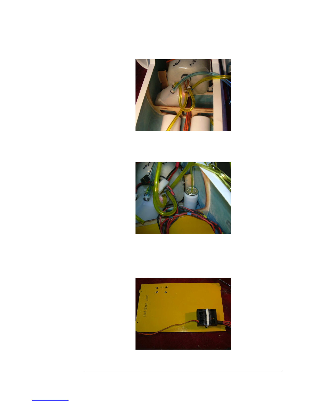
122. Epoxi the UAT in place and connect the fuel line to the main tank.
Figure 122
123. Epoxy or silicone the propane tank to the other side of the fuse as
shown.
Figure 123
124. Secure your ECU to the engine tray. You can lay out your tray any
way you want, just keep distance between the pump and ECU and RX.
Figure 124
46
46
4646
Page 47
F E I B A O L - 3 9 A L B A T R O S
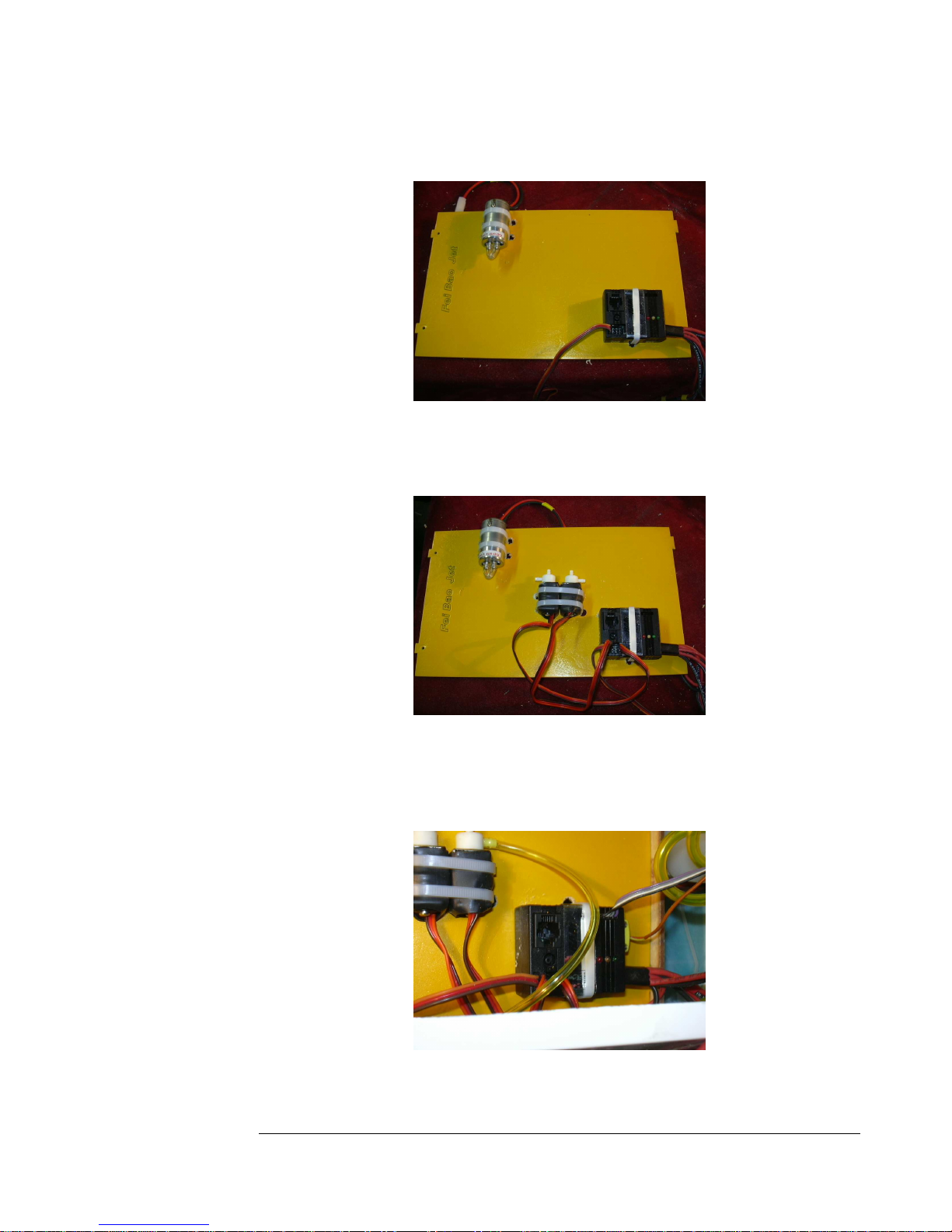
125. Install your fuel pump to the engine tray.
Figure 125
126. Install your fuel and gas solenoids. Again, you need to be aware of
the cockpit tub, and make sure whatever you install works with the tub.
Figure 126
127. Place the engine tray into the fuse and secure with two screws.
Connect your ECU to the engine and receiver according to the
manufacturer's instructions.
Figure 127
47
47
4747
Page 48
F E I B A O L - 3 9 A L B A T R O S
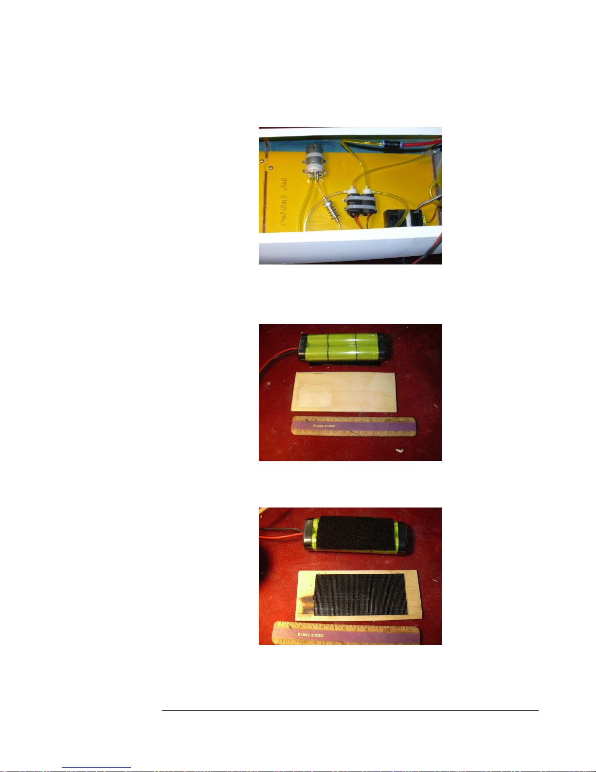
128. Complete the plumbing of the fuel and gas systems according to
your engine's instructions.
Figure 128
129. Make up a one eighth inch plywood plate to mount your ECU
battery.
Figure 129
130. Install velcro on the battery and the plate.
Figure 130
48
48
4848
Page 49
F E I B A O L - 3 9 A L B A T R O S
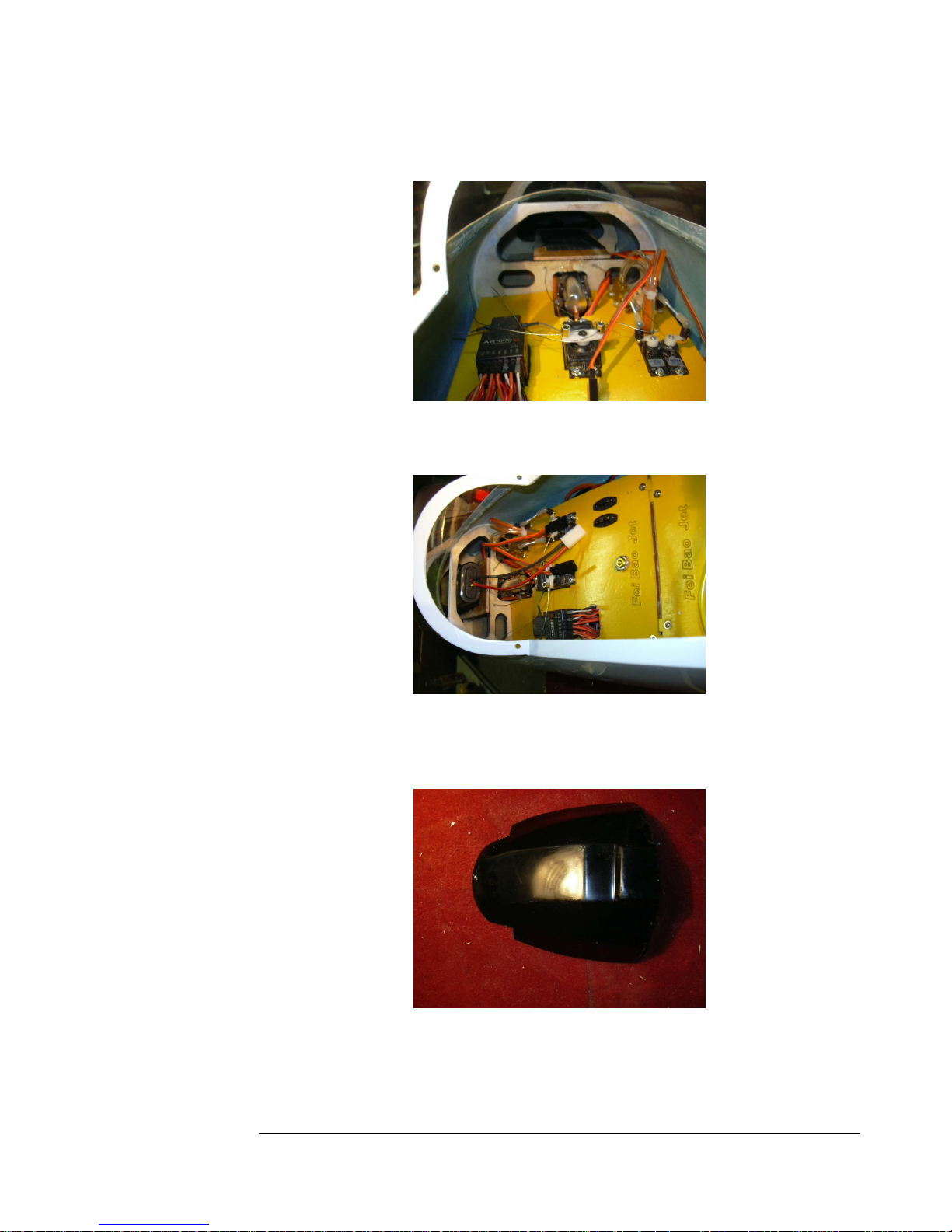
131. Epoxy the plate into place atop the two formers in the nose.
Figure 131
132. Put the ECU battery onto the tray with velcro.
Figure 132
133. Test the fit of the dashboard into the fuselage. You may need to
notch it as shown to fit over the former.
Figure 133
49
49
4949
Page 50
F E I B A O L - 3 9 A L B A T R O S
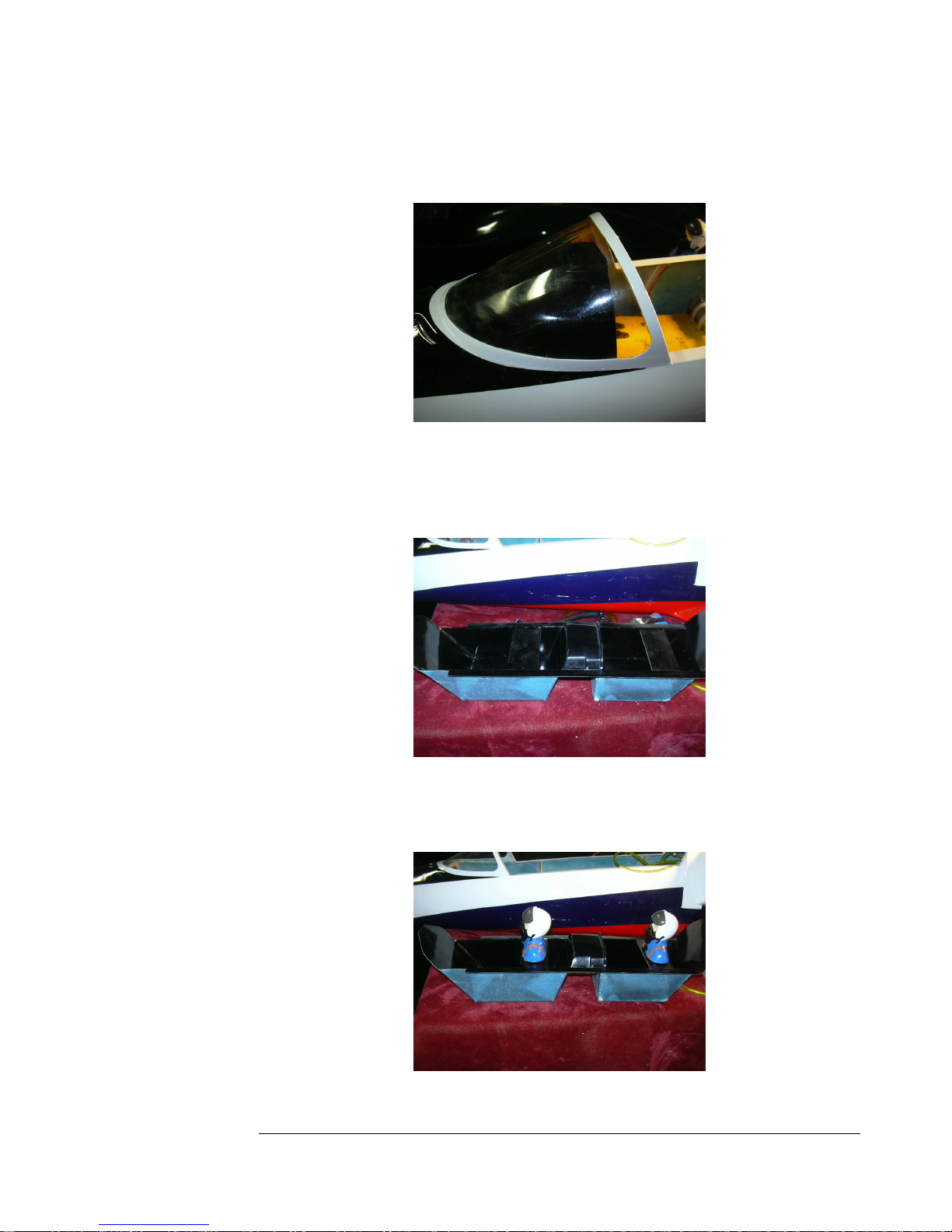
134. Epoxy or silicone the dashboard into place when satisfied with the
fit.
Figure 134
135. You may detail out the cockpit tubs as you like. A simple and
cheap solution is to make up two plywood plates, paint them black, and
epoxy in place as shown.
Figure 135
136. Two pilot bust figures can be glued to these plywood platforms
when dry.
Figure 136
50
50
5050
Page 51
F E I B A O L - 3 9 A L B A T R O S
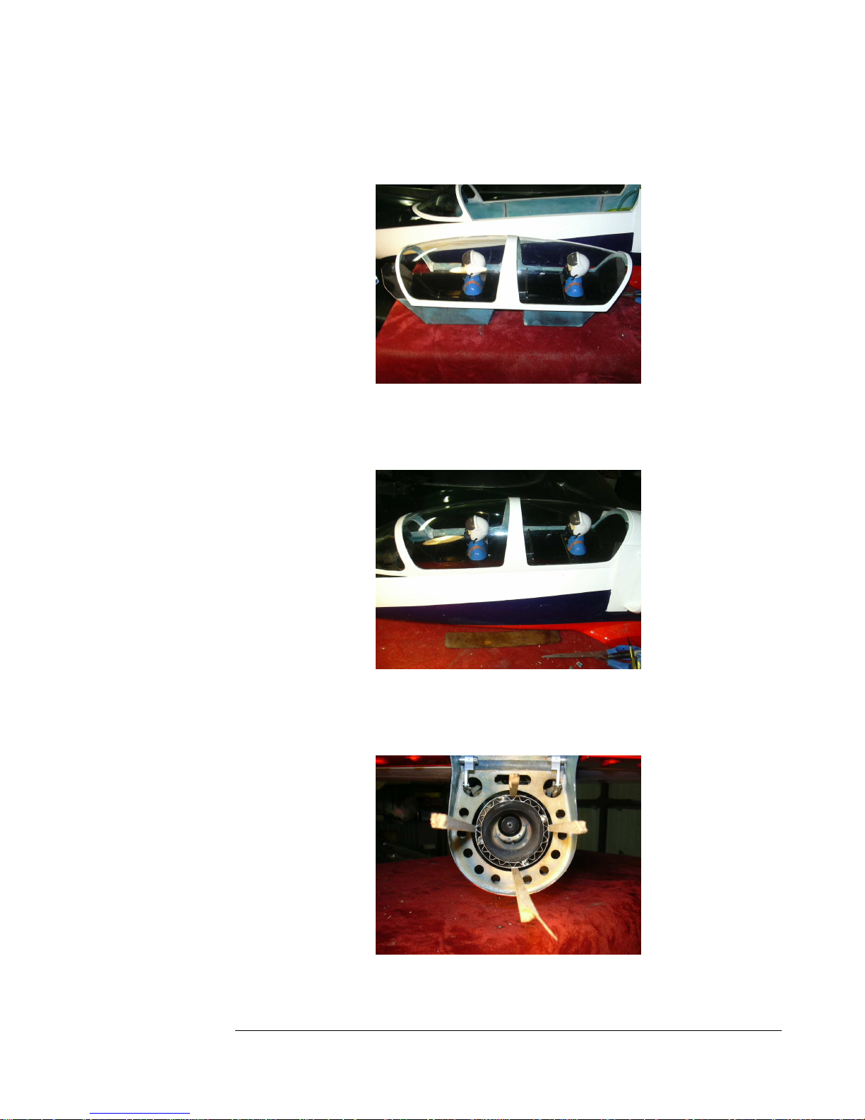
137. Test fit the cockpit tub into the canopy and fuse and trim as
required.
Figure 137
138. Slip the tub inside the canopy frame and glue into place with
silicone or epoxy. When dry, latch the canopy into place.
Figure 138
139. Temporarily center the tailpipe in the rear former using scrap balsa
sticks.
Figure 139
51
51
5151
Page 52
F E I B A O L - 3 9 A L B A T R O S
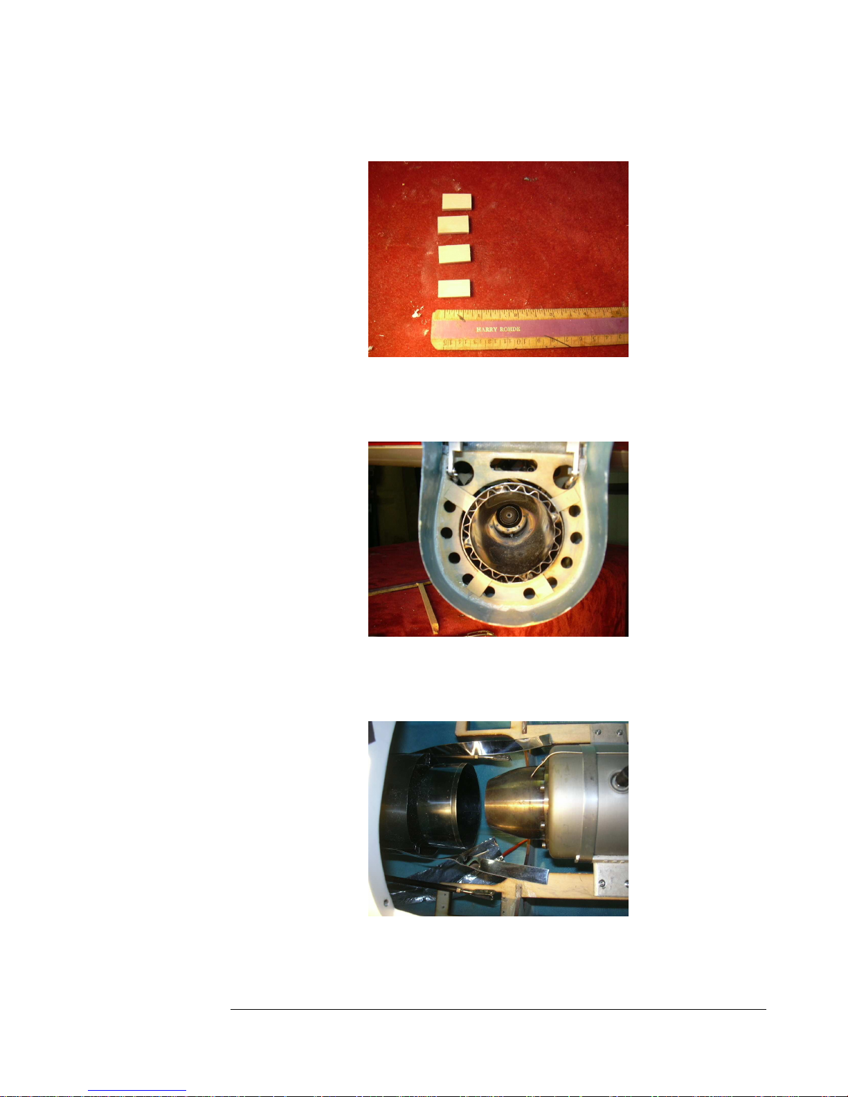
140. Cut four plywood rectangles to center the pipe.
Figure 140
141. Epoxy the plywood pieces into place to center the tailpipe and
remove the balsa scraps when dry.
Figure 141
142. Measure the distance from the pipe to the tail cone of the engine
according with the turbine manufacture recommendations.
Figure 142
52
52
5252
Page 53
F E I B A O L - 3 9 A L B A T R O S
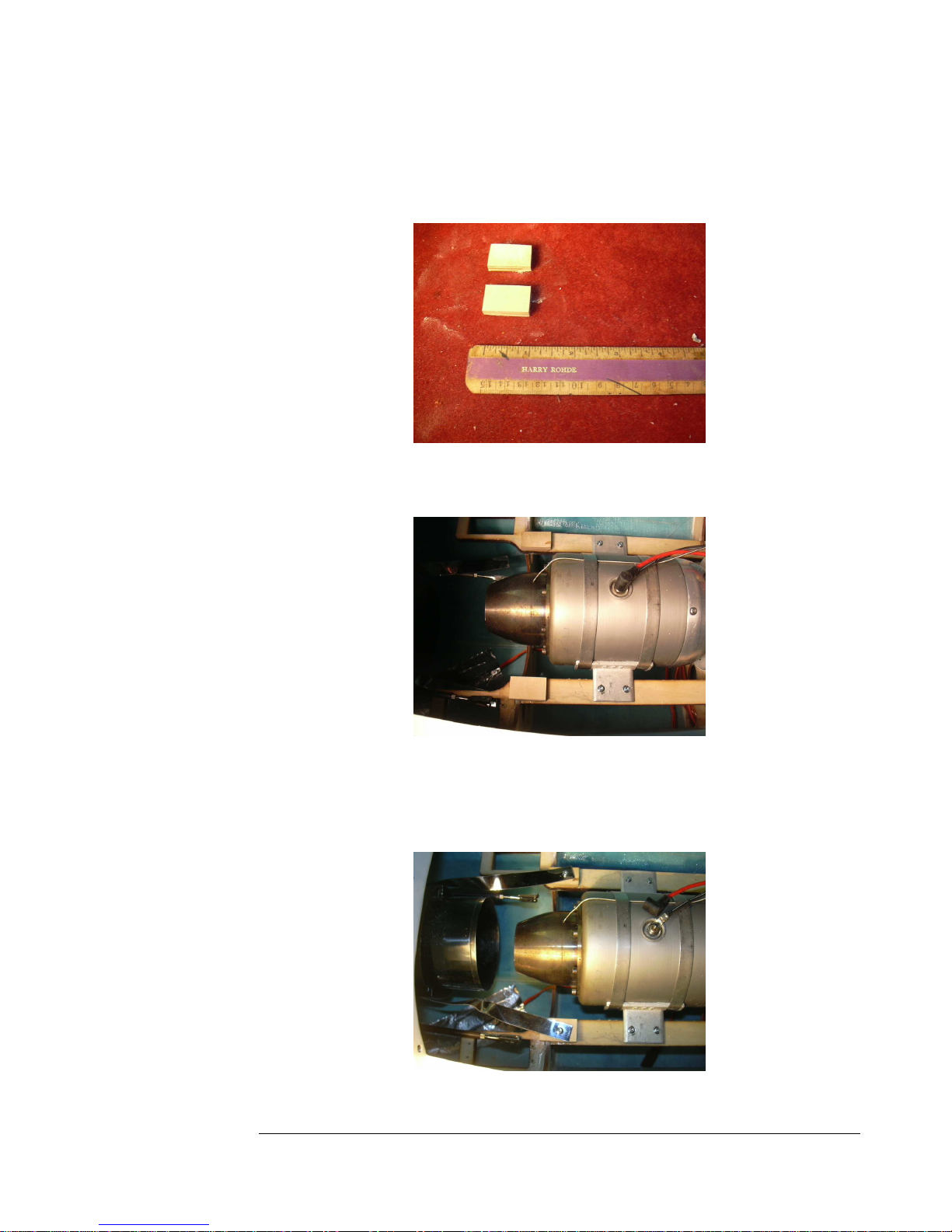
143. Make up two plywood blocks...the height of these needs to be
adjusted to get the pipe at the right height to center on the tail cone of
the engine.
Figure 143
144. Epoxy the blocks to th engine mounts.
Figure 144
145. Drill pilot holes through the mounting tabs and the blocks and
secure the pipe with two screws. Be sure to maintain the correct distance
between pipe and engine.
Figure 145
53
53
5353
Page 54
F E I B A O L - 3 9 A L B A T R O S
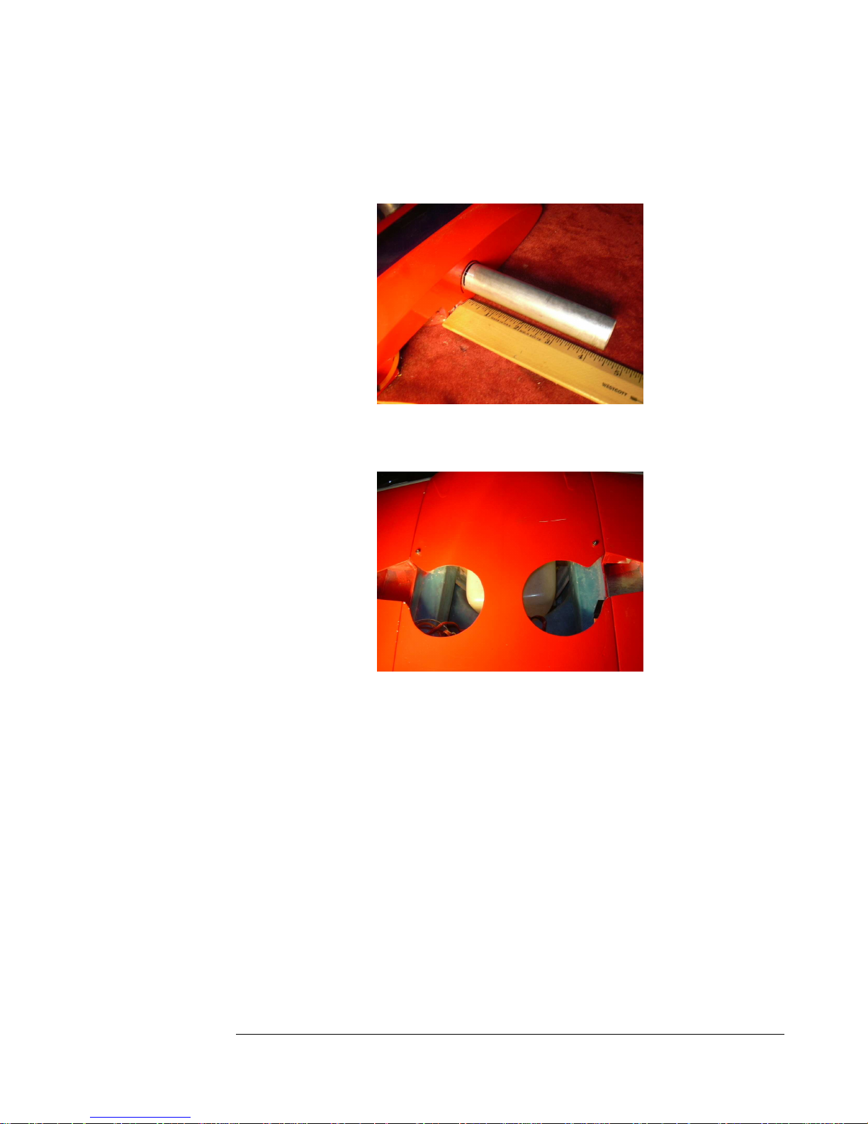
146. Slide the main spar into the fuse. Make a mark four and a half
inches from each end, to make sure you keep the spar centered when
putting on the wings.
Figure 146
147. The wings are secured with the two provided bolts. Be sure to not
over tighten them and strip the threads.
Figure 147
54
5454
54
Page 55
F E I B A O L - 3 9 A L B A T R O S
Congratulations, you have completed construction on your Fei Bao L-39.
See the Pilots Notes for balance and control throws.
Technical data:
Center Of Gravity:
Balance your plane in the middle of the main spar, with the UAT full and the main tank
empty and the gear retracted. You can move the CG forward or aft for later flights, but
this is a nice safe position. Be cautious about playing it too safe and going too far
forward, you don't need to. Avoid adding lead if possible, move equipment forward if
you can. There is a slight trim change aft as the fuel burns off, but it is not significant.
The plane should lift off by itself on takeoff, even though it may have a slightly negative
angle of attack due to the nosegear strut compressing.
Engine Selection:
The L-39 was designed for engines from 12-18 pounds of thrust. It will fly fine, in a
very scale-like manner, with only 12 pounds of thrust. 14 will give a little more push,
and a P-70 or Wren Supersport in the 16-18 pound class should give very vivid
performance. Be aware that while you can indeed use larger 66mm engines like the
P-80, they do add more weight, and you might not be able to realize their full thrust
potential using the stock FeiBao tailpipe. There is certainly room for a larger diameter
pipe if you feel the need.
Control Throws:
Ailerons: Due to their gapless sealed construction, they may be more powerful than
you expect, so do not overdo the throws. First flight should be 15mm up and down.
You can adjust this later if you want more.
Rudder: 25mm left and right
NosegearL No more than 10mm left and right. You can set up dual rates to have
higher rates for taxying if need be.
Elevator: 15mm up and down
Flap: 35mm, measured at the trailing edge at the root. You will need at least 2mm of
down elevator trim with full flap to keep the nose from rising. Half flap requires no trim.
55
5555
55
Page 56

F E I B A O L - 3 9 A L B A T R O S
Conclusion:
It's a very nice plane to fly. It is quite docile, and the stall is soft and straight forward,
and landings are easy. It is a nice first turbine model for someone with some highspeed experience. It is capable of most aerobatic maneuvers, and it looks very scale
in the air. Enjoy your new model, when you chose FeiBao, you chose the most
advanced, most prefabricated models available, and you have the full support of the
factory and the extensive dealer network. Any time you feel a need, please reach out
and get in touch, FeiBao is always glad to help in any way possible.
Credits:
Written by Curtis Mattikow
Test Pilot: Curtis Mattikow
Maiden
at Floyd Bennett Field
56
5656
56
Page 57

57
5757
57
 Loading...