

Fei Bao F-4 Phantom II Assembly Manual

F E I B A O F - 4 P H A N T O M I I
FEI BAO JETS
F-4 Phantom Assembly Manual
In collaboration with R/C Jet Models
1111

2222
DISCLAIMER:
THIS IS NOT A TOY
and damage to life, limb, and property. The manufacturer and its distributors cannot control how
you assemble this model, what equipment you use to fit it out, or how you fly it, and can assume
no liability whatsoever for any damages that may occur when you fly your aircraft. By
assembling this model, you are agreeing to indemnify and hold blameless the manufacturer
and/or his agents from any and all torts and liability associated with the use of this product.
Once you have assembled the aircraft, you are the pilot in command and assume any and all
responsibility for the use of the model and any damages that might occur by flying or attempting
to fly this aircraft.
R/C model jets require a high level of skill in both their assembly and their flying. If you do not
feel confident in either your building or flying skills, PLEASE seek assistance from more
experienced modelers. It is a wise idea, no matter what level of skills you possess, to have a
second experienced modeler go over your installation after assembly. A second set of eyes may
spot a problem you have missed. If you have not flown a model like this before, it is HIGHLY
recommended that you get an experienced turbine pilot to do your maiden flight. Very often, the
first few seconds of a maiden flight are critical until the aircraft is trimmed out, and having an
experienced pilot at the controls can make the difference between a wrecked aircraft and once
that enjoys many hundreds of flights. Be sure to select a suitable field for flying...take the time
to find a large paved runway if at all possible, especially for test flights, until you feel comfortable
getting the aircraft in and out of smaller grass fields.
Congratulations on your purchase of the Fei Bao F4 Phantom II.
.
This is a high-performance miniature aircraft, capable of high speeds
Before you begin
• Clean and inspect all parts. Inventory them against the parts list at the end of the manual
and notify the kit supplier of any missing components as soon as possible.
• If the paint scheme you have selected is glossy, it is recommended that you apply a coat of
wax. This will help resist dirt, stains and fingerprints during construction, and will provide
some limited protection against errant glue.
•
Vacuum out the remnants of packing materials that remain in the fuselage.
While the kit is comprehensive, there are additional parts required, as follows:
• Recommended Servo List (JR)
• Elevators: (2) 8611a
• Aileron: (2) 8611a
• Flaps: (2) 8611a
• Rudder: (1) 3421
• Nose Steering: (1) 2721
• Retracts: (2) 351 or equivalent
• Brakes: (1) 351 or equivalent
• Other Parts
• BVM UAT (optional)
• ½ inch Velcro straps to secure fuel tanks
• Wire twist tie (optional)
3333
• Blue Loctite
• Glues: Thin CA, 5 minute epoxy, Aeropoxy
• Electronic gear sequencer
• Brake valve
• Batteries, regulator and switch
•
Servo extensions (length may vary, depending on receiver placement)
Construction
The order of construction may be changed to suit your personal preference,
however, there are a few points to note:
• The fuel system is more easily accessed if the fuselage halves have not been joined
• The model is more easily worked in a tight space if work is completed on each fuselage
section before they are joined
• The incidence of the main wheels must be set prior to attachment of gear doors, thus, the
fuselage should be completed before the wings.
The retract system in the prototype is operated by two valves. The two way valve controls gear
up and gear down. The gear doors stay open with the gear extended, so the door open-air lines
are simply connected to the gear down lines. The door close airlines are connected to a second
one way valve, which is operated by an electronic sequencer. The sequencer delays the
operation of the door close valve, allowing the gear to retract.
Step 1: Fuel System
Construction begins with the fuel system. Once the nose is bolted on the aft fuse, the forward
fuel tank that sits between the intakes is more difficult to install, so now is the time to complete
this step.
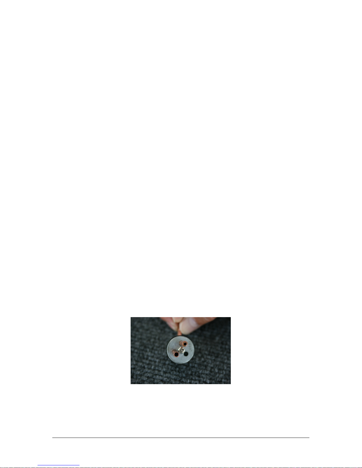
It is recommended that you disassemble and inspect the tank cap hardware. As photo 1 shows,
the process used to cut the tubes may leave behind a rim that constricts fuel flow and could
result in excess tank pressure and leakage. The vent tube to the top of the picture shows what
the constriction looks like before repair, while the fuel tube on the lower left shows what the
tubing should look like after clean up. If the tubing is not constricted, skip forward to the leak
check.
Loosen the Philips head screw and remove the stopper assembly from the tank.
Use a small, round Perma-Grit rat tail file or an Exacto knife to remove the excess metal.
You will need to inspect the ends of all tubes.
Photo 1

4444
The tube that the pickup line connects to inside the tank may also need to be shortened to
approximately 12 mm for ease of installation through the tank orifice. When finished, make
sure to blow out the metal fragments and clean up any sharp edges.
While the components are apart, check the Tygon pickup line for equal lengths in both saddle
tanks. They should be long enough to reach the back of the tanks without being so long as
to restrict their ability to move to the top of the tank when the aircraft is inverted.
You should also notch the vent tube with a small file to provide for continued air flow should
the tube come into contact with the top of the tank.
Make sure the bends to the vent tubes applied at the factory have not restricted airflow to
any significant extent. Also, check the Tygon for any nicks or cuts and secure to the tubing
with wire ties before re-assembly.
Once the tanks are back together, they should be leak checked before installation in the
aircraft. Connect extra lengths of fuel tubing to the fuel and vent lines and submerge the
tank in water. Pinch off one line and gently pressurize the tank by blowing into the other,
looking for signs of air bubbles. If the tank shows evidence of air leakage around the vent
cap, tighten the Philips head screw and check again. If you have a stubborn leak, you can
re-tap the inner plate for a slight larger 6/32 cap head bolt.
It is recommended that you mount the forward fuel tank so as to be able to remove it for
maintenance in the future.
Before installing the saddle tanks, check the spar receiver bolts to make sure the nuts are
secure. Plug the wings into the spar receivers and move them up and down, tightening the
locknuts until there is no evident play.
Cut two strips of 6 mm ply approximately 180 mm long by 12 mm wide. Also cut four Velcro
straps approximately 12 mm wide by 180 mm long.
Using two 7mm wood screws per strap, attach two Velcro straps approximately 20 mm from
the end of each ply rail. Be sure to attach the straps so they overlap, holding the flat part of
the tank firmly against the ply rail.
The lower rail can be glued to the inside of the front former, but the upper rail should be
attached with screws accessed from the engine compartment such that the upper rail may be
removed. Strap the tank in place.
Photo 2 Photo 3
For extra security, place several pieces of scrap foam between the tank and the intakes, and
also between the top of the tank and the top of the fuse to keep it from shifting during flight.
To mount the saddle tanks, begin by routing two narrow 12 mm slots toward the outside of
the engine mounting rails. These should be positioned approximately 60 mm inside the front
and rear formers.
Cut two Velcro straps 350 mm long and thread them through the slots. Position the saddle
tank with the curvature to the outside and the stopper assembly at the front, and tighten the
straps. The tank should be canted slightly inward to allow the fuel lines to clear the inside of
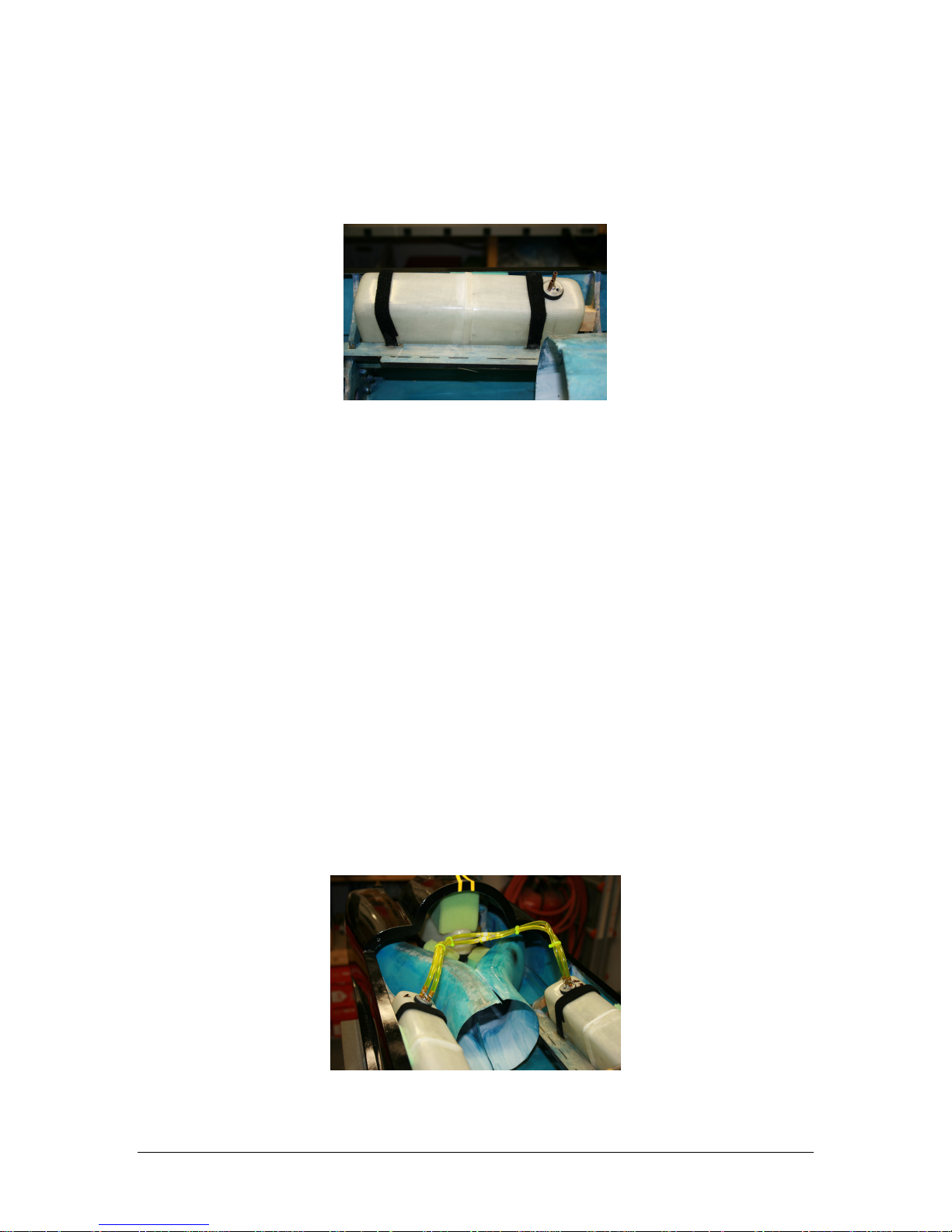
5555
the hatch. Place a piece of scrap foam between the top of the tank and the side of the
fuselage to hold the tank in this position.
Cut a piece of scrap balsa block to act as a spacer between the front of the tank and the
former. Make sure you can access the forward wing spar mounting bolts, and then attach
the spacer block to the front former with a drop of CA.
Photo 4
When you are happy with the position of the tank, test fit the hatch and check for clearance.
If everything checks out, glue the Velcro to the slots routed in the rail with 5-minute epoxy.
Also apply epoxy to the point where the Velcro strap meets the side of the fuselage, being
careful not to glue the tank to the strap. This will keep the tank from shifting.
Repeat all steps for the other saddle tank.
Check the fuel lines for nicks and cuts as you proceed through the next steps.
Connect two pieces of fuel tubing approximately 180 mm long to the fuel pickup tubes in
each saddle tank and bring them together with a “Y” fitting just above the intakes.
Repeat this process for the vent tubes in the saddle tanks.
Run a length of fuel tubing from the “Y” fitting connected to the fuel pickup tubes to the vent
tube of the main center tank.
Attach a length of tubing to the “Y” fitting connected to the vent tubes on the saddle tanks.
The vent fitting will be positioned in the forward fuselage … a pigtail of approximately 200
mm extending past the forward former should be sufficient.
Connect a length of tubing that will run to the fuel pump to the fuel pickup tube on the main
center tank.
Wire tie all connections at this time
If you use plastic wire ties to bind the fuel tubes together for a neater installation, make sure
not to over-tighten and pinch down on the flexible fuel tubing.
This completes the fuel system.
Photo 5
6666
Step 2: Vertical Fin and Rudder
Before assembly begins, inspect the glue joints between the fin ribs and the outer skin. These
may be seen through the servo mounting hole and the forward inspection cut out. If there are
gaps in the glue, fill them in with a little Aeropoxy.
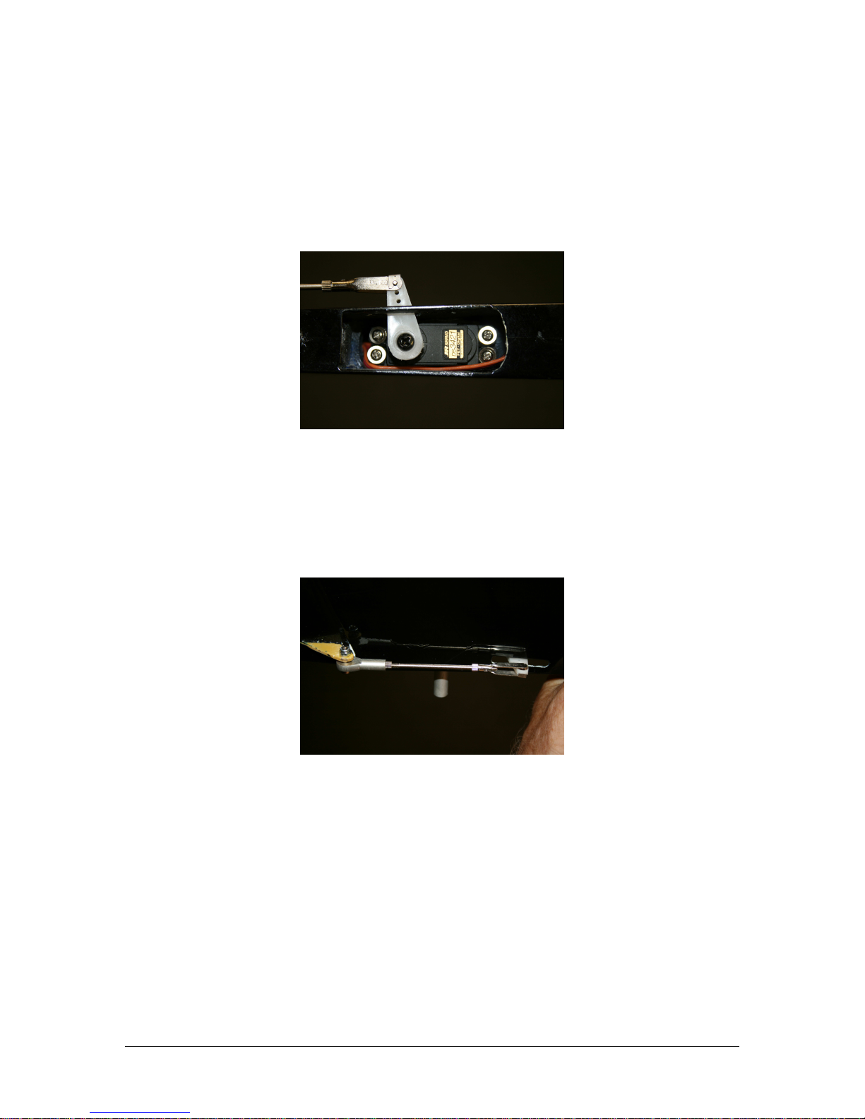
Mount the rudder servo, with the spindle toward the rear of the fin. You may need to
enlarge the mounting hole just slightly.
Photo 6
Using a JR Matchbox or your receiver, power up the servo and set it at neutral. Attach the
control arm at a vertical position. Enlarge the strut slot size in the fin slightly with a small file
if the arm binds.
Assemble the rudder linkage. Use the rod that is approximately 190 mm long. You will need
to enlarge the hole in the control horn with a 7/64 inch drill for the rod bolt. Do not over
tighten this bolt as the rod will bind as the rudder is actuated.
Photo 7
Connect your servo extension and secure with tape or heat shrink tubing.
Secure fin to aft fuselage with 12mm bolts and large 12mm washers. Use Loctite on the
threads.
 Loading...