

Page 1
F E I B A O F 1 8 – f
FEI BAO JETS
F18-f Assembly Manual
Written by Jeff DeCaluwe
In collaboration with R/C Jet Models
1
Page 2

F E I B A O F 1 8 - f
DISCLAIMER:
THIS IS NOT A TOY. This is a high-performance miniature aircraft, capable of high speeds
and damage to life, limb, and property. The manufacturer and its distributors cannot control how
you assemble this model, what equipment you use to fit it out, or how you fly it, and can assume
no liability whatsoever for any damages that may occur when you fly your aircraft. By
assembling this model, you are agreeing to indemnify and hold blameless the manufacturer
and/or his agents from any and all torts and liability associated with the use of this product.
Please inspect all parts before beginning assembly. If any parts appear to be suspect, contact your
dealer or the manufacturer for repair or replacement BEFORE you begin. Once you have
assembled the aircraft, you are the pilot in command and assume any and all responsibility for
the use of the model and any damages that might occur by flying or attempting to fly this
aircraft. R/C model jets require a high level of skill in both their assembly and their flying.
If you do not feel confident in either your building or flying skills, PLEASE seek assistance from
more experienced modelers. It is a wise idea, no matter what level of skills you possess, to have
a second experienced modeler go over your installation after assembly. A second set of eyes may
spot a problem you have missed. If you have not flown a model like this before, it is HIGHLY
recommended that you get an experienced turbine pilot to do your maiden flight. Very often, the
first few seconds of a maiden flight are critical until the aircraft is trimmed out, and having an
experienced pilot at the controls can make the difference between a wrecked aircraft and one that
enjoys many hundreds of flights. Be sure to select a suitable field for flying...take the time to find
a large paved runway if at all possible, especially for test flights, until you feel comfortable
getting the aircraft in and out of smaller grass fields.
Congratulations on your purchase of the Fei Bao F18-f Jet.
BEFORE YOU BEGIN:
· Clean and inspect all parts. Inventory them against the parts list at the end of the manual
and notify the kit supplier of any missing components as soon as possible.
· If the paint scheme you have selected is glossy, it is recommended that you apply a coat of
wax. This will help resist dirt, stains and fingerprints during construction, and will provide some
limited protection against errant glue.
· Vacuum out the remnants of packing materials that remain in the fuselage.
While the kit is comprehensive, there are additional parts required, as follows:
· Recommended Servo List (Hitec)
· Elevators: (2) 5955TG
· Aileron: (2) 5245mg
· Flaps: (2) 5955TG
· Rudder: (2) 5125mg
· Nose Steering: (1) 5955TG
· Retracts: (1)HS81mg or equivalent
· Brakes: (1) HS81mg or equivalent
· Air Brakes: (1) HS81mg or equivalent
Page 3

F E I B A O F 1 8 - f
2
· Other Parts
· Buna smoke tubing for inside the fuel tanks
· BVM UAT or alike highly recommended
· Wire twist tie (optional) but recommended or alike
· Blue Loctite
· Glues: Medium CA with accelerator, 35 minute epoxy, Aeropoxy or Hysol kit
· UP3 Control Valve or Electronic gear sequencer
· Brake valve
· Batteries, regulator and switch
· Servo extensions (length may vary, depending on receiver placement)
· Smoke system (Optional)
· 3mm Air line, 5 different colors, approx.. 1 to 2 meters each.
· Cockpit with pilots (Optional)
Keep this in mind as you proceed: Look at EVERY assembly step you finish, and ask yourself:
“Could this step cause my airplane to crash?”
A chain is only as strong as its weakest link, and this is a high-performance aircraft that will be
very intolerant of sloppy assembly techniques. Even the smallest component is important and can
cause the loss of your airplane, so take the time to do things right. Or Redo them if they are
wrong. Careful work will result in a long-lasting plane that gives you years of pleasure, one loose
component could result in the complete loss of the aircraft and all the components inside it, and
someone can even get hurt. So pause every once in a while when building it and double-check
your workmanship.
Introduction:
You have chosen a model that represents the pinnacle of ARF technology. While there is not a
lot of building to do, there is enough to keep you busy for more than a few evenings.
Even if you have assembled other ARF jets, we still highly recommend following our assembly
sequence and procedures anyway. Chances are it will save you a lot of time, prevent you from
running down dead ends, and perhaps remind you of a few small things that might end up saving
your aircraft.
We have tried to arrange a construction sequence that will allow you to keep moving forward,
rather than standing around waiting for glue to dry before you can proceed to the next step.
Just because the model is almost completely built does not mean you can rush through the final
assembly. You need to employ fine craftsmanship every step of the way, turbine models are
critical. Keep this in mind with everything you do, every part you install...look at the work you
just did, evaluate it critically, and ask yourself "is this going to potentially crash my airplane?" If
there is any doubt about the work you have done, back up, and re-do it properly.
Page 4

F E I B A O F 1 8 - f
3
We start assembly in a sequence as:
1. Installing door hinges, doors and all air cylinders, for a minimal fee, the factory will
install them all for you, which I believe is well worth every cent.
2. Pneumatic lines for doors, retracts, brakes and air brakes.
3. Fuel tanks, replacing internal lines and installing external lines with a vent exiting the
fuselage, (Optional) Smoke tank with fuel lines and vent to exit fuselage.
4. Gluing the flap hinges, aileron hinges and rudder hinges also all control horns.
5. Elevator balancing, servos, extensions and linkages
6. Wing and rudder servo covers, servos, extensions and then linkages to each horn
7. Installing Ordnance on wings.
8. Front wheel servo with pull-pull linkages or another Non pull-pull assembly (Optional)
9. Cockpit with pilots (Optional)
10. Preparing the Equipment tray, Header tank, ECU, turbine valves, Fuel pump with shutoff
valve, Air valves, Servos for the air valves, receiver, voltage regulators with switches,
(Optional) Smoke pump with shutoff valve. (Optional) Air failsafe, and or (Optional)
Steering Gyro.
11. Installing equipment tray and making room for cockpit
12. Connecting the forward to the aft fuselage
13. Carbon fiber bypass, thrust pipe & engine
14. CG (Center of Gravity), Batteries and Air tanks
15. Transmitter setup & Maiden Flight
Before we start, Some info about Adhesives:
The correct adhesive to use for most procedures is either white Hysol 9462 made by Locktite or
white Aeropoxy made by BVM and for a little faster setting time there is a clear Vpoxy made by
BVM. These are very strong epoxies which are thixotropic. "Thixotropic" means it does not run,
Hence it stays where you put it. It is infinitely superior to regular epoxy, even slow-setting
epoxy, for our purposes, because of this characteristic. Regular epoxy will run down hill with
gravity as it dries, usually taking it away from where it is supposed to be. We will be using this
process with regular epoxy only once to balance the elevators. A good example is in the
hinges...using regular epoxy, a good portion of the glue will migrate down away from the hinge
into the inside of the wing as it dries, and you won't even know it is happening. Hysol or BVM’s
poxy stays where you put it. The downside is it takes overnight to dry properly, but we have tried
to arrange things to keep you busy while waiting for the glue to dry. We also highly recommend
that you only use a proper dispensing gun, and only the long-type mixing nozzles.
We have found over extended use that the short nozzles do not mix this glue enough, and only a
thin nozzle and gun will let you fill the hinge and control horn holes properly with glue, you can
not do it by mixing it on a flat surface and then trying to get the glue in the proper place by a
brush or stick. You can buy a complete kit with a gun, nozzles, and two cartridges of
glue from your dealer for approximately $60 to $80. Consider it a great investment, the glue is
the best you will use. One cartridge is plenty to assemble your F18-f.
4
Page 5

F E I B A O F 1 8 - f
1: INSTALLING DOOR HINGES, DOORS AND CYLINDERS:
This ARF has the doors and all cylinders already installed by the factory and has been omitted
from the manual at this time. If you have to install the cylinders and doors, try to view the next 5
pictures for there placement. As they say a picture can say a thousand words.
WORKING WITH PNEUMATIC SYSTEMS
The F18-f uses pneumatic brakes and retracts. If you follow a few tips, you should have very
reliable, leak-free operation. Neatness counts.
All airlines should be secured to the airframe to keep them from flopping around or getting
kinked. Use tie wraps or holders for this. The other very important thing is to cut off the end of
each airline as square as possible before installing it on the nipple. You can either purchase a
professional tube cutter from your dealer (they are approximately $10), or you can make up a
little jig to hold the airline and keep a sharp, new razor blade perfectly upright as you cut.
Either one works, just ensure that all ends of all airlines are cut off dead square.
Make sure all airlines are pushed ALL THE WAY onto their nipples. They should not need to be
secured otherwise, but you can add fine wire, safeties wraps or even shrink tubing if you like.
Make sure all left and right matching airlines are the same length, particularly the brake lines, or
you will get uneven retraction or braking action. It's worth taking the time to get everything
pneumatic right the first time, as having your landing gear fail to retract is not THAT bad, but
having it fail to deploy can really ruin your day and the paint on the bottom of your model.
2: PNEUMATIC LINES FOR DOORS, RETRACTS & AIR BRAKE.
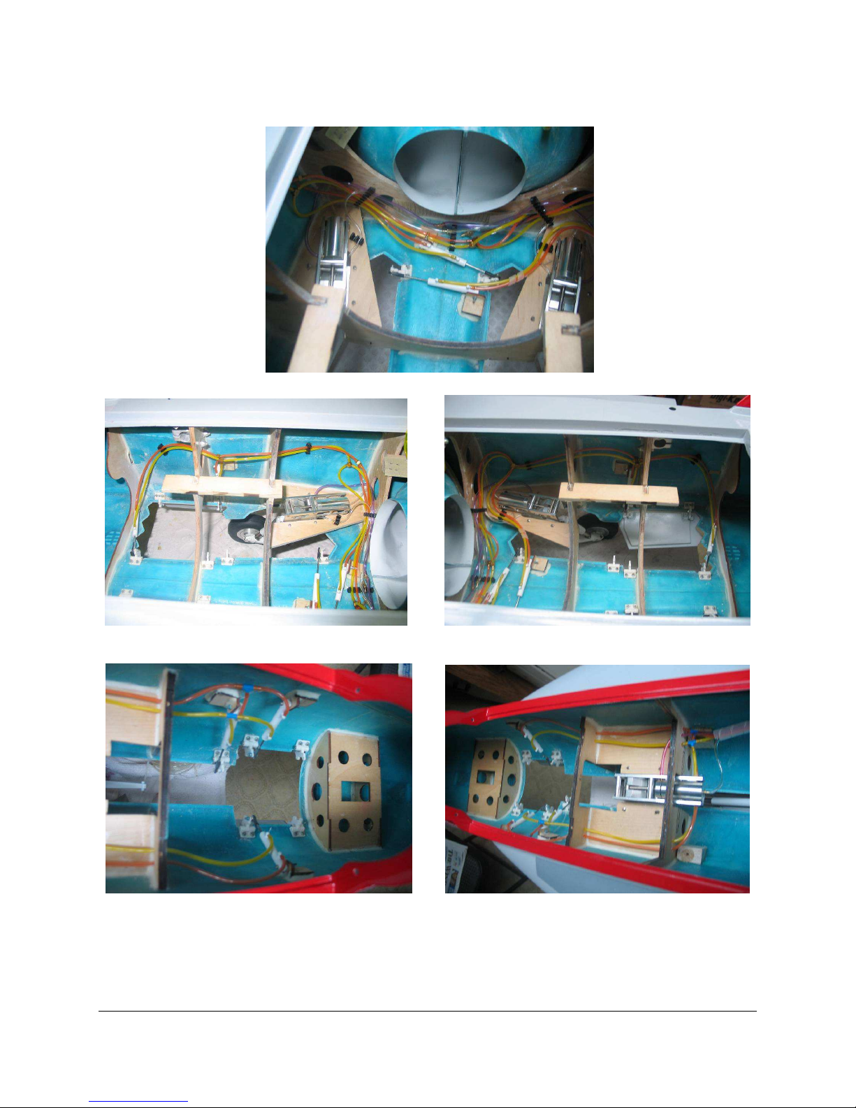
Attach Orange air line to each door cylinder so that when air is applied it will cause the gear
doors to open. Do this for each door cylinder. To understand how to route and show
approximately how much line is needed for each cylinder, view the next 5 pictures.
Repeat last step but use Yellow air line on the opposite side of each cylinder which will make
the doors close.
Next connect the same colors with “Y” adapters ending with that color exiting the front of the
mid section of the fuselage and having approx. 1 foot extra length sticking out to connect to the
air valves later.
Repeat again for the front nose section. But only have the end of the lines be about even with
the rear of the mid section to connect to the air values later. Remember neatness is vital, using
tube holders at key points helps a lot, as the following pictures show.
5
Page 6
F E I B A O F 1 8 - f
.
Connect 2 - 8" pieces of any colored airline (I have used blue on one side and white airline on
the other side for clarity, but that is not included in the kit) to both air brake cylinders then tee
the same colors together and add an other piece about 12” to extend forward from the center of
the fuselage to the nose like the other lines to connect to a air control valve later.
6
Page 7
F E I B A O F 1 8 - f
Attach Red air line to each retract cylinder so that when air is applied it will cause the gears to
deploy. Use enough line to have the lines exit 1 foot as the previous door lines did before.
Repeat the previous again but use Purple air line on the retract side of the gear cylinders.
Attach a 14" length of CLEAR tubing to each brake nipple.
Like you did for the other airline colors, connect the remainder of the clear brake line to a Y
connector and to the two brake lines.
Secure the brake lines to the struts by using clear tape or tie wraps. Do not over tighten the tie
wraps and restrict the air flow through the lines. There are also clips especially designed for this
that can be purchased from you dealer.
Check that each retract is properly secured into place.
Check the wheel alignment for toe in and toe out. The first spring should be compressed before
you adjust the wheels by putting the weight of the model on a table. The wheels should be
pointing straight forward. If they are not straight, loosen the trunion bolts to straighten them and
then retighten the trunion bolts. It is good practice to recheck tightness of all bolts just in case
the factory missed something.
Blue thread lock is also a good practice to use on any threaded bolts as it works like a lock
washer.
Never use the Red thread lock as it is for a permanent install and requires lots of heat to be
removed.
3: FUEL TANK SYSTEM
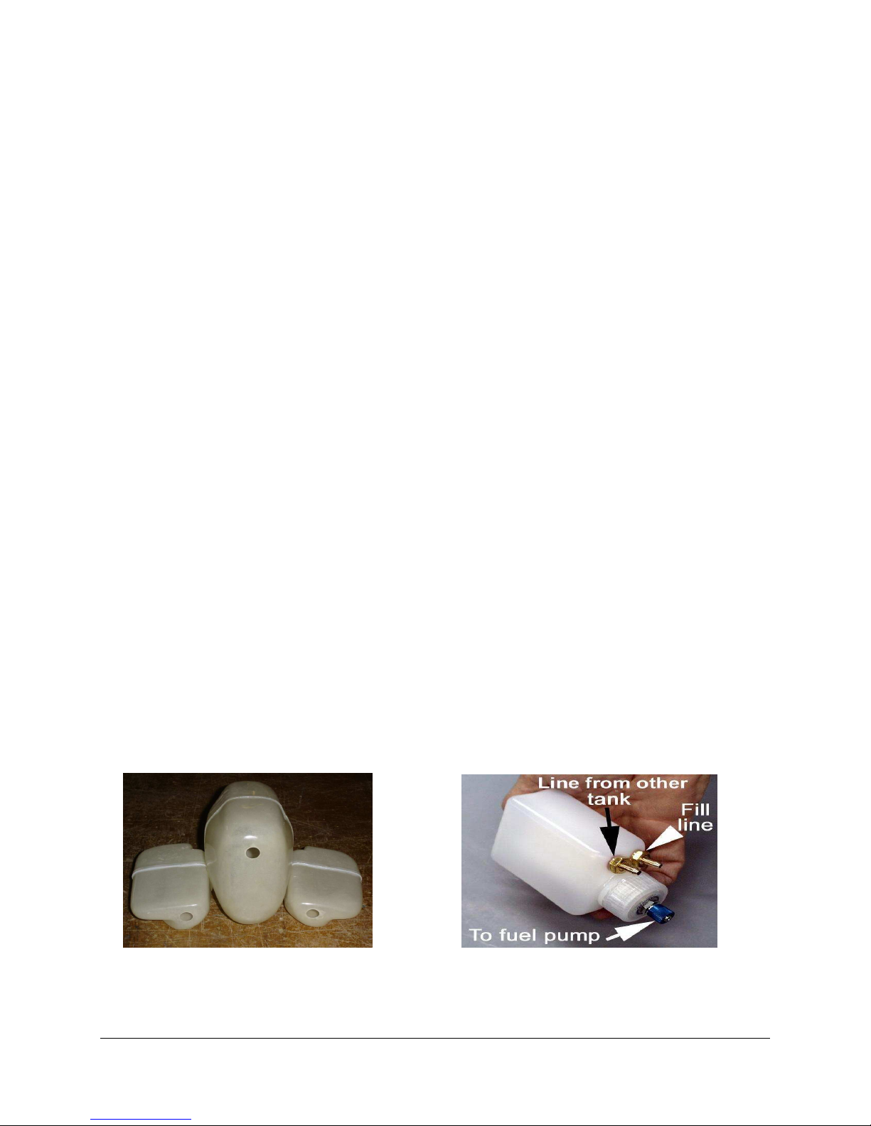
The F18-f has a 3 tank fuel system. The main is 88 oz with 2 - 40oz saddle tanks which are just
behind the CG of approx. 5½” to 6¼” from the wings leading edge. They are connected in
parallel, then “Y” connected to the main tank and then to a UAT or similar header tank of choice.
The total capacity is 168oz or 5.25 Liters. BVM UAT
There is not much to go wrong, but like the pneumatic system it does need to be done right the
first time with some careful craftsmanship. Like the airlines, all fuel lines should be cut off
square. Each fuel connection must be given a tie-wrap or fine wire for extra leak security.
Page 8
F E I B A O F 1 8 - f
7
Everything needs to be very clean, especially the inside of the tanks. Depending on the kind of
header tank you use, The BVM UAT as shown above should be installed at an approx. 45-degree
angle to allow air bubbles to exit from the top fill line. You can also make up your own header
tank with a bubbles filter, or a geometrically centered pickup, but any way you do it, you should
not attempt to fly without a header tank system or you will most likely have flame outs all the
time caused by air bubbles.
The tanks will be installed in the fuselage and secured with Velcro but you should double
check each one by removing them and then removing the stoppers as explained next, then blow
them out, be sure that no debris of any sort is left in them before proceeding. This is a vital step,
do not omit this step.
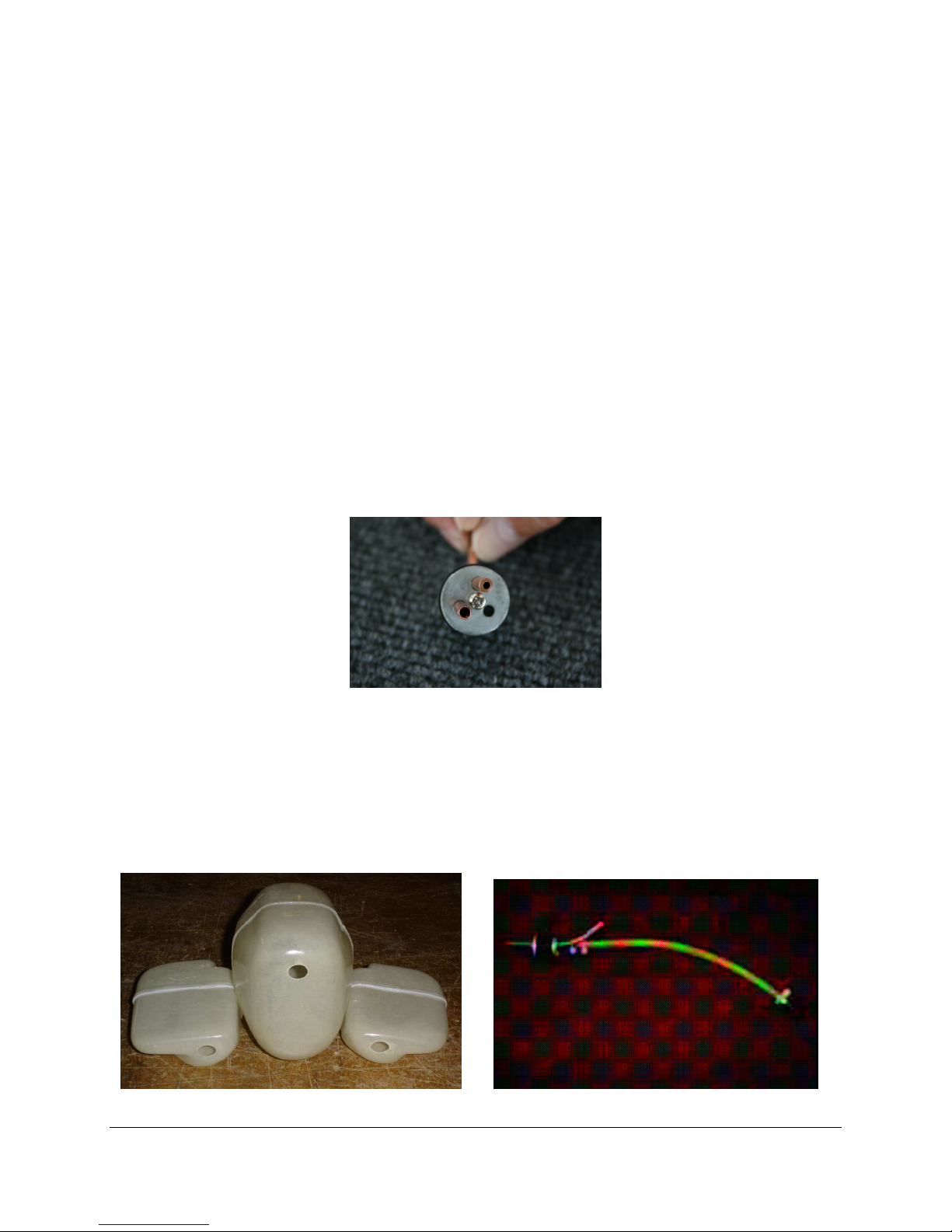
It is recommended that you disassemble and inspect the tank cap hardware also as the next
picture shows, the process used to cut the tubes may leave behind a rim that constricts fuel flow
and could result in excess tank pressure and leakage. The vent tube to the top of the picture
shows what the constriction looks like before repair, while the fuel tube on the lower left shows
what the tubing should look like after clean up.
To remove the stoppers loosen the center screw about 10 or 15 turns and then try to wiggle the
stopper back and forth as you pull on the tubes and rubber stopper slightly, you may need to use
a screw driver to pry on the rubber to break the seal..
If the tubing is not constricted, skip to the next step. Use a small, round Perma-Grit rat tail file
or an Exacto knife to remove the excess metal. You will need to inspect the ends of all tubes.
When finished, make sure to blow out the metal fragments and clean up any sharp edges.
Page 9
F E I B A O F 1 8 - f
8
There is also a problem with the internal tubing supplied at the factory in the tanks. After some
time in kerosene the tubing tends to get stiff and hard. We recommend changing these lines with
flexible black buna smoke tubing which remains flexible.
After getting the assembly out, remove the factory provided tubing and reinstall with the
recommended tubing, Assemble as the above right picture shows. Insert the assembly and check
that you use enough tubing to allow the clunk to touch in the bottom back corners. When
satisfied, use tie wraps or fine safety wire for security to prevent the tubing and clunk from
falling off. Gently bend the vent line to reach the top of each tank, You should also notch the
vent tube with a small file to provide for continued air flow should the tube come into contact
with the top of the tank.
Insert the stopper and clunk assembly into the tanks and tighten the screw. Do not over tighten
the screw and strip out the stopper assembly. It only needs to be tight enough to prevent leaks.
Mark a “V” over the vent line on each tank to remind you where the vent line is.
Testing tanks for leaks, attach some tubing to one of the tanks, immerse the tank into water,
and blow into the tubing to check for leaks. Do this for each tank. When satisfied there are no
leaks, put the tanks aside. Do not use a compressor or hand pump to test the tanks as too much
pressure could blow the tanks apart at the seams. Then you will have a big job to repair them
which would be to scuff, clean and glue them again with an epoxy. The next step is not required
but may be done to your liking just as an extra security seal on the tanks.
Optional Fuel Tank Reinforcement
It has been experienced on a couple of occasions were the fuel tanks have leaked. They were
caused by too much pressure during the fueling process. The concave side of the tanks, tend to
flex under this pressure and may crack the lapped glue joint. The following modification has
cured the problem. It is also sensible to be careful during the fueling procedure to slow the rate
of fuel going in as the tank becomes near full.
a) Solvent clean outside surface then use #80 grit sandpaper to scuff the surface area.
Page 10
F E I B A O F 1 8 – f
9
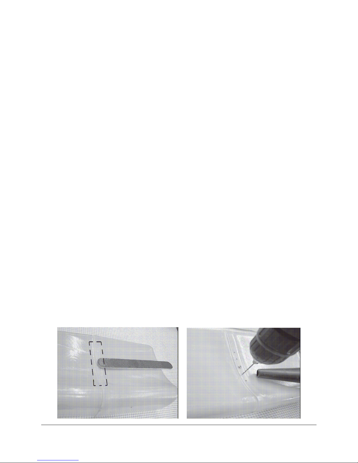
b) Drill (5) 1/16” holes about 1/2” apart with the middle hole near the center of the concave side
of the tank. Center the holes fore and aft on the lap joint. Have a helper hold a vacuum nozzle
such that the drilled residue is removed.
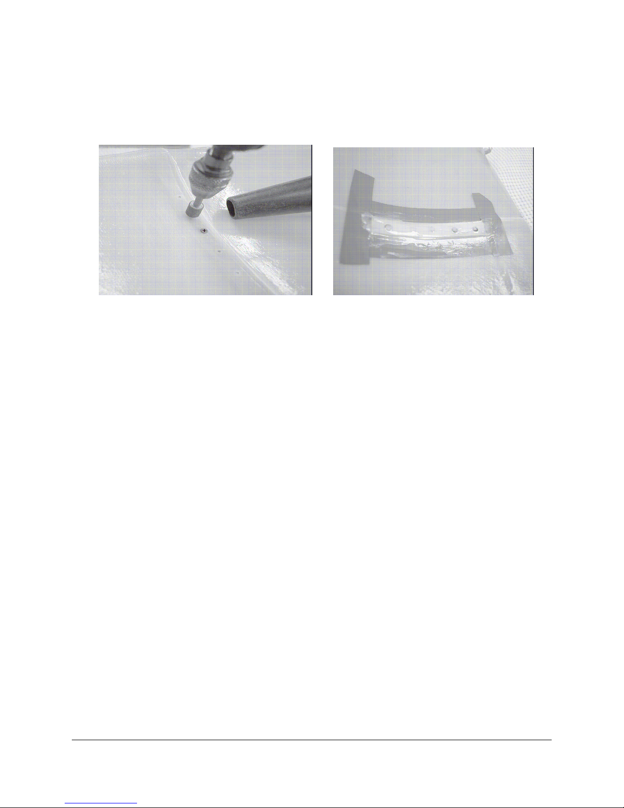
c) Use a PermaGrit # RF9UF countersink tool (with vacuum) to allow the Poly Ply Screw head
(BVM Part# 5725) to seat near flush with tank surface. Solvent clean 10 Poly Ply screws then
apply a small amount of poxy to each hole and insert the screws.
d) Tape the area as shown and apply a coat of epoxy. Remove the tape while glue is wet.
Put aside overnight to dry / cure.
4: GLUING FLAP, AILERON, RUDDER HINGES & CONTROL HORNS
While there are many ways of doing this, this method will let you do all the surfaces at once,
assures proper alignment and movement, and lets you move on to other assembly work while the
glue on the hinges dries. Most techniques involve gluing one side of the hinges, letting it dry and
then doing the other side the next night. This method lets you do both sides at once, and
guarantees proper alignment if needed. This model has the control surface hinges pre glued on
the control surface sides by the factory for alignment purposes and to help keep each surface in it
placement left and right. All you have to do is glue the other half to the wings and rudders.
Follow the procedure fully for best results whether gluing both sides or not.
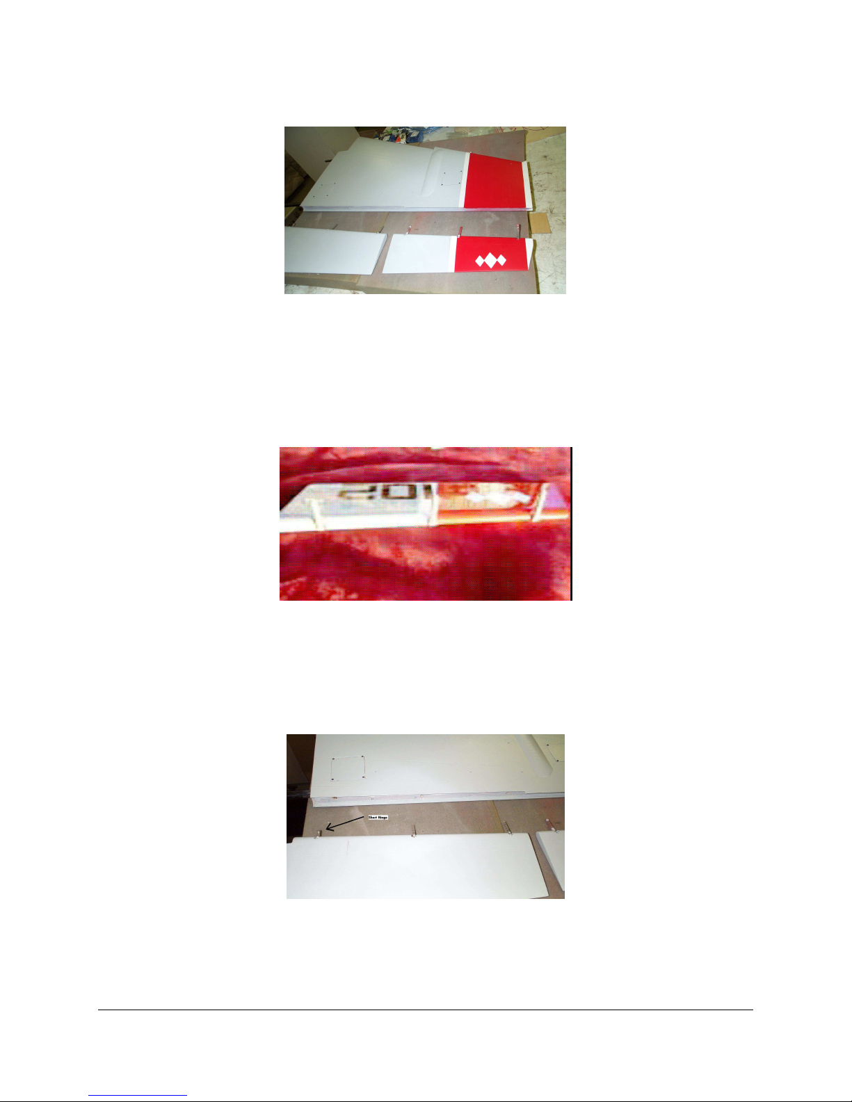
Put a towel, cloth or something soft like foam down on your bench to prevent the painted
surfaces from being scratched. If not in place, locate all the control surfaces to their correct place
on the wings and rudders. Check for proper mating, hinge location, and movement on all
surfaces. Starting with either wing
Remove the control surfaces.
Page 11
F E I B A O F 1 8 - f
10
Coat the center portion of each hinge with petroleum jelly. Use enough to keep any glue from
sticking, but make sure you do not get any petroleum jelly on the ribbed portion of the hinge that
needs to be glued. If you get any on this portion you must clean it off with Acetone or some
other kind of strong cleaner, then sand / scuff to allow adhesion. If you do not get proper
adhesion, the control surface could come out in flight, which in turn would most likely cause a
crash, depending on your flying skills.
. Coat the leading edge of each control surface with a thin layer of petroleum jelly to keep any
glue from sticking.
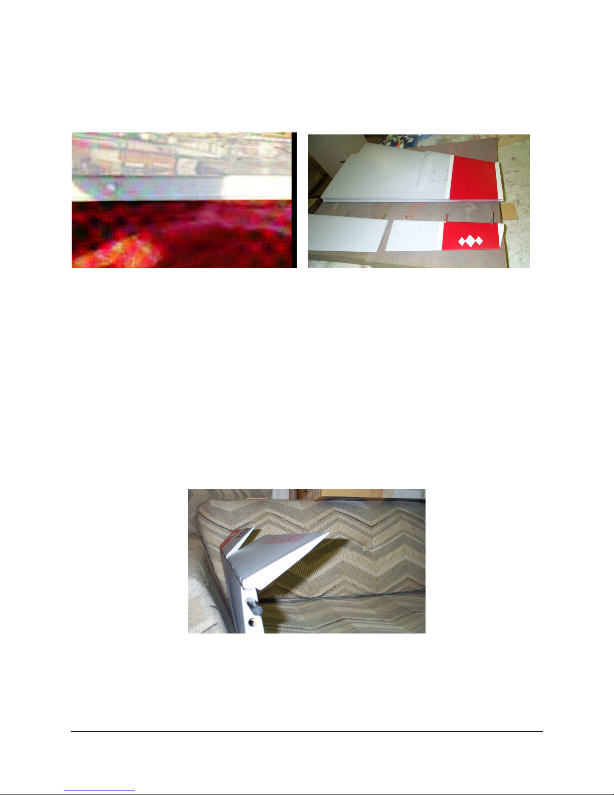
Note the flap hinges closest to the fuselage has been shortened at the factory to prevent them
from protruding into the carbon fiber spar.
Use a piece of 40 grid sand paper to scuff up the short ends by sanding them in a round
motion to roughen in a grove that gives a ribbed affect, like the larger ones have. Giving some
extra attention on these should give you proper adhesion.
Page 12
F E I B A O F 1 8 - f
11
Get a wing and fill the three holes with Hysol or BVM epoxy. Be fairly generous with the
glue. The ONLY place where glue should be is in the hole itself...clean up any excess right away.
To help for an even better adhesion you may want to put some glue around each hinge staying
away from the pinned area with petroleum jelly on it.. Only use enough to get the hinge covered
with a thin film using to much glue just adds weight and will collect around the holes entrance.
Keeping the hinges at 90 degrees to the control surface, gently push the control surface into
place on the wing / rudder. Keeping it at right angles keeps the hinges from getting pushed
further into the surface and getting misaligned. When you get to the final quarter inch or so of
insertion, start reducing the angle of the surface until the surface slides home the final bit.
Carefully align the trailing edges of the flap and aileron surfaces, using the trailing edge of the
wing at the tip, and the paint stripes, as a guide.
Check for adequate freeness and movement on the surfaces, paying particular attention to
having enough downward movement on the flaps.
When you are satisfied, tape both the flap and aileron into place with masking tape to prevent
any misalignment while drying, set this assembly aside, and do the same procedures to the other
wing.
Repeat last 8 steps for the rudders. When completed set all these assemblies aside to dry
overnight.
Page 13
F E I B A O F 1 8 – f
12
5: ELEVATOR BALANCING, SERVOS, EXTENSIONS & LINKAGES
Some may say not to balance your elevators because it may cause flutter but I tend to differ, If
your servo gear mesh and linkage is tight with out any play there should not be a problem
whether it is balanced or not and if there is play in the gear mesh or linkage then you will
probably get flutter either way. By balancing the elevators you reduce the extra strain on the
servos gear train and with the precise digital servos we have today, balancing will stop the
bussing sound you will get from the weight of the elevators pushing down from the gravity.
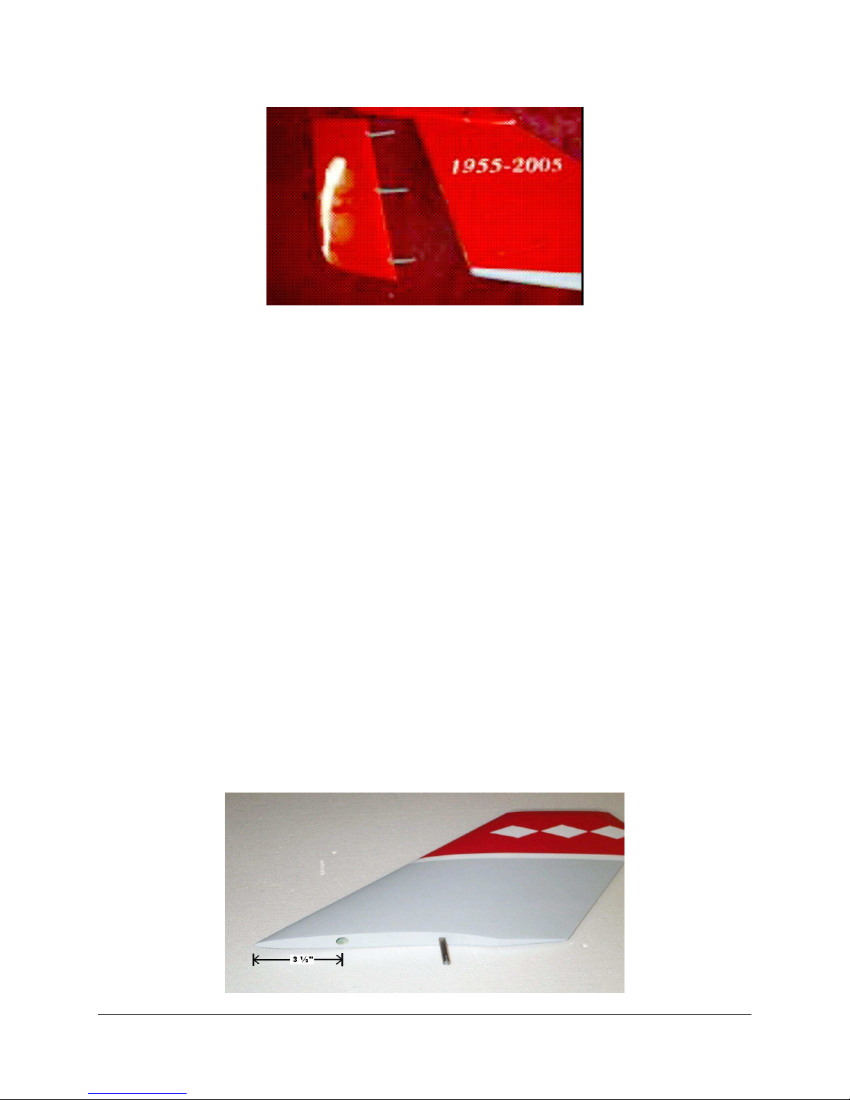
To balance the elevators drill a hole approx. ½” in diameter with either a dremel or a drill on
the inside flat edge of the elevator, approx. 3½” from the corner of the leading edge, view picture
below. If you decide to use a drill, a tip to prevent breaking the elevators seam is to start out
with a smaller bit and then go bigger till it is approx. ½”. I have used about 80 grams of BB’s for
weight but anything like small pieces of lead, pellets, buckshot or birdshot will work in the hole
to get the elevator to balance. To create a centerline, use a ruler and make a mark with a pencil at
the edge of the elevator straight inline with the center of the shaft protruding from the elevator.
Use your finger on this pencil spot as a balance point and another finger as a resting area for the
shaft. Keep adding weight till it starts to stay down or not move in a horizontal position. Do not
let the elevator fall backwards from a horizontal position to prevent the weights falling to the
trailing edge. After you get it close to balance. You will need to take out enough weight to
account for the epoxy you are going to put in the hole to secure the weight inside. Approx. 1oz of
30 minute epoxy which weighs about 30 grams should do the trick. Mix and pour the epoxy in
the hole then cover the hole with some tape and let it stand vertical so the weight is on the
bottom but at a slight angle to allow the epoxy to cover the hole as it dries.
Page 14
F E I B A O F 1 8 - f
13
Repeat previous step for the other elevator.
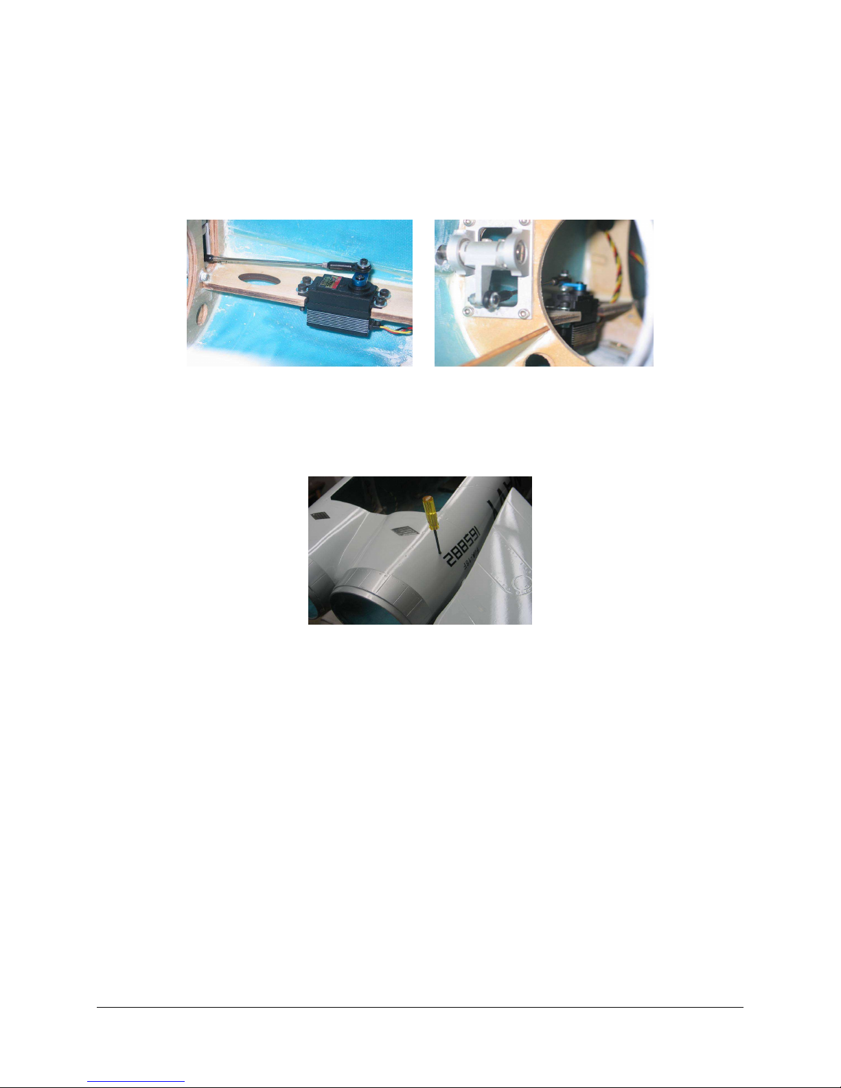
Install the elevator servos as show in the pictures below and do not use the rubber grommets as
they may cause flutter if there is to much play.
Attach a 36" heavy-duty 22-gauge extension to each servo. Tape the connections for safety.
You can also drill a hole through the bottom on each side of the rear fuselage to allow easy
access to the hex bolts that secure the elevators which allows easy removal to transport your
model..
6: WING & RUDDER SERVO COVERS, SERVOS, EXTENTIONS
Remove the servo cover from the rudder servo bay. Keep the orientation of the servo cover
correct, do not flip or rotate the servo covers, as there may be slight variations in the screw holes
and they may not fit perfectly if you rotate the covers. You can do both rudder servo assemblies
at the same time, if you like.
Test fit your rudder servos. You want a metal-geared, high-powered mini servo. A standard
servo will not fit, and full micro servos generally lack enough mounting area on their ears to
make them really safe, even though many of them have plenty of power for your rudders. You
could also fit a surface-mounted flat servo. In this case, the Hitec 5125MG is excellent for this
application. Beware of just gluing the servos into place...if you break a servo gear and have to
remove the servo for maintenance, you are in big trouble.
Attach a 36" heavy-duty 22 gauge extension to the servo. Tape the connection for safety.
Feed the extension through the rudder
Page 15
F E I B A O F 1 8 - f
14
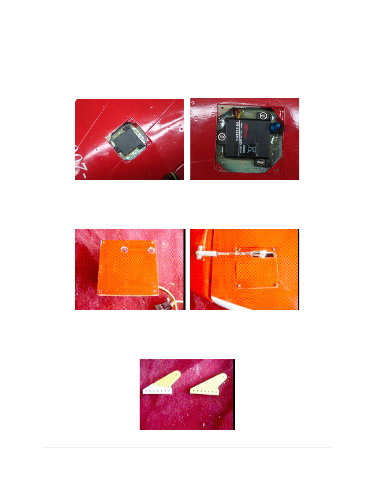
You can hold the servo with wooden blocks by cutting 3 for each side then drill holes through
them then screw them to the servo, then put a little epoxy on the side that goes to the inner wing.
And clamp it there over night to dry or you can purchase servo wing holders from your dealer
that glue on the inside of the wing and then there is 3 screws that hold the servo in place as seen
in the pictures.
Cut a slot in the cover for the servo horn approx. 1” long which should do for the movement of
the servo then drill a hole at each end like the lower picture shows and draw a line on each side
as shown then use a new sharp exacto blade to cut the lines. After satisfied with the slot screw
the cover back in place.
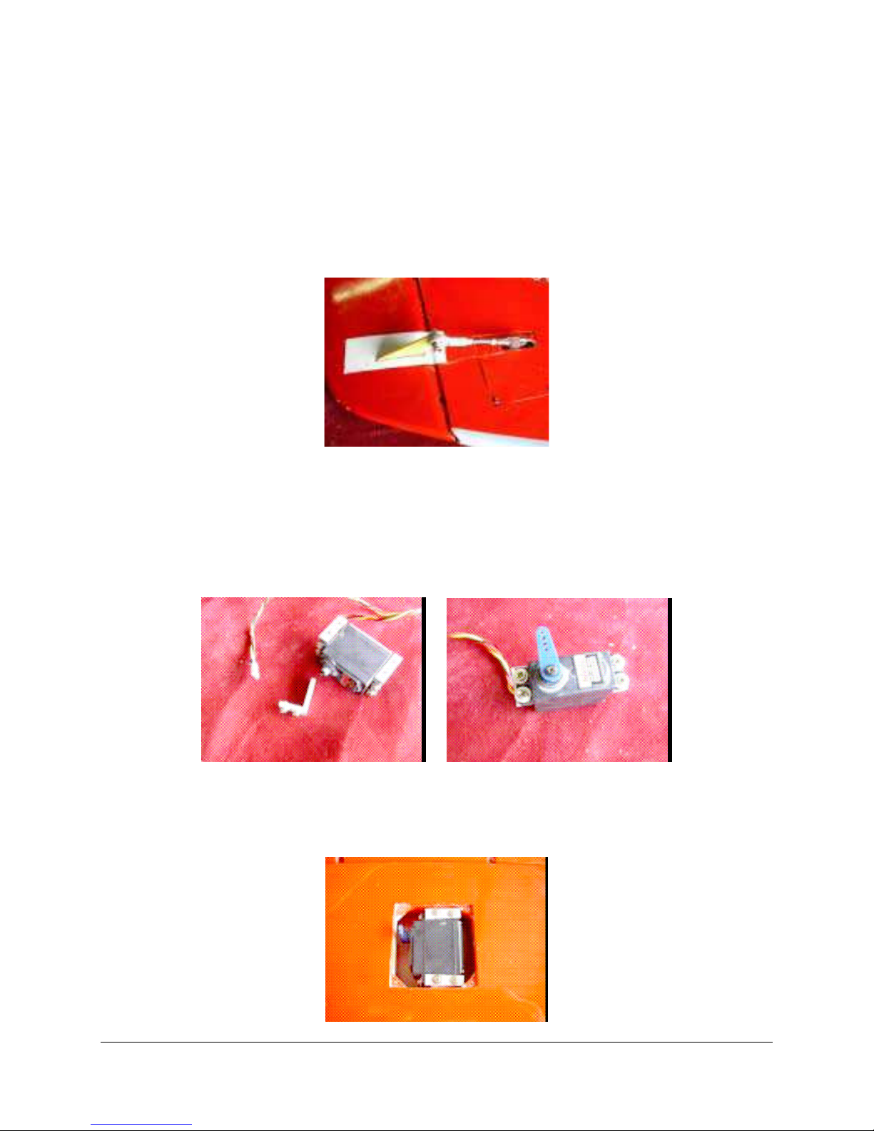
Attach the provided linkage to the servo horn
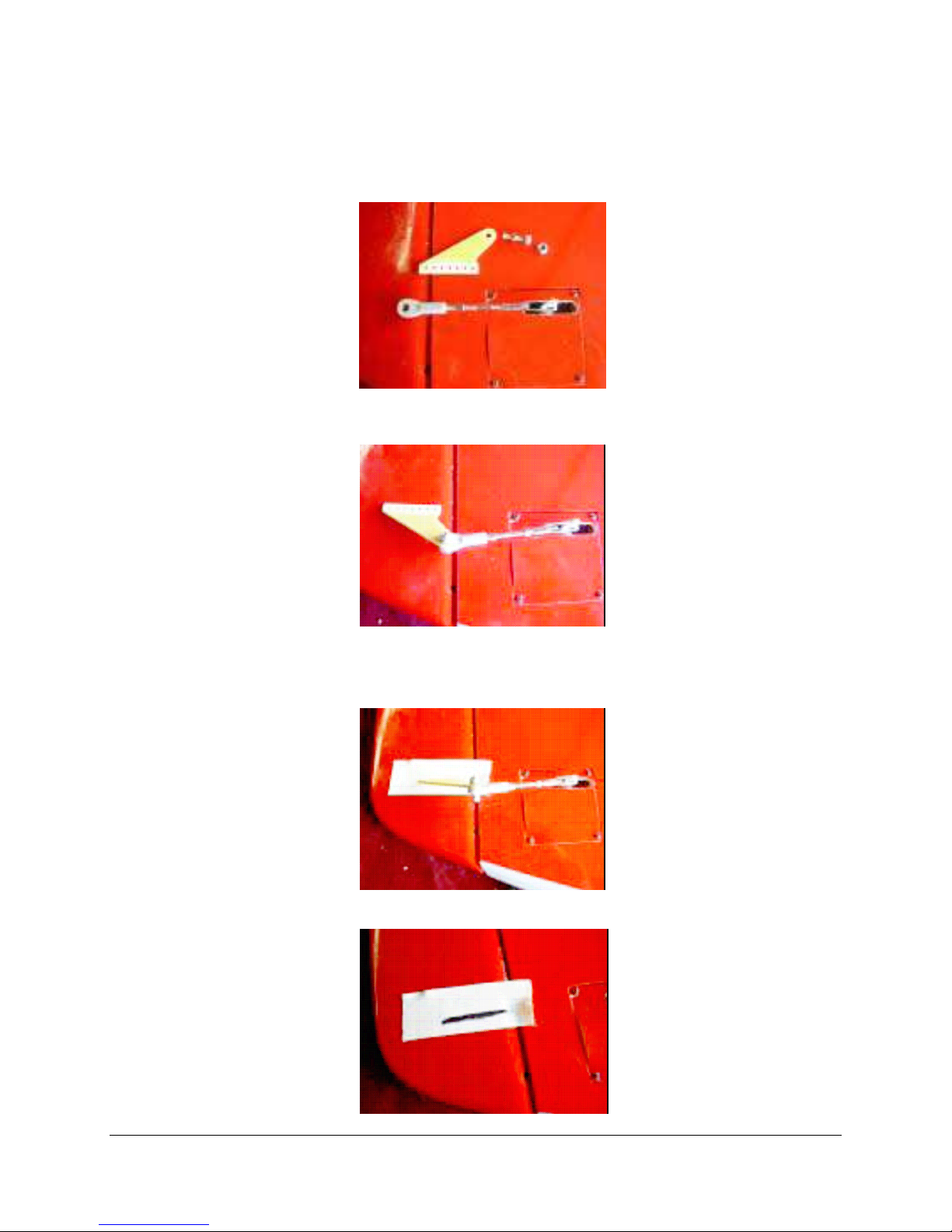
Prepare all 6-control horns. Roughen up the bottom portion on both sides by using 40 grit
sandpaper or a dremel to give you a better gluing bond.
Page 16
F E I B A O F 1 8 - f
You will also need to open up the top holes to accommodate the bolts for the ball links. Go
15
very slowly on this, if the holes end up oversize, you will need to replace them. Or they will give
you flutter. Do all 6 control horns at once.
Bolt a horn into place, and adjust the linkage to the correct length
Put a piece of masking tape on the surface of the rudder where the horn will go. This tape will
protect the surface while you work there, and keep any markings you need to make from being
on the surface itself.
Mark the location of the horn.
Page 17
F E I B A O F 1 8 - f
Cut the slot for the horn. Power tools are a little dangerous here, as if they slip. you can drill all
16
the way through to the other side of the surface. Use an exacto and many small strokes, only
resort to the Dremel if you run into a really hard portion. You do not want the slot to be a super
tight fit on the horn, you want room for glue in there, but nor do you want huge gaps.
If you wait until all the horns on all the surfaces are done, you can glue them all at once, which
will save you glue, glue tips, and time. So hold off for now on gluing.
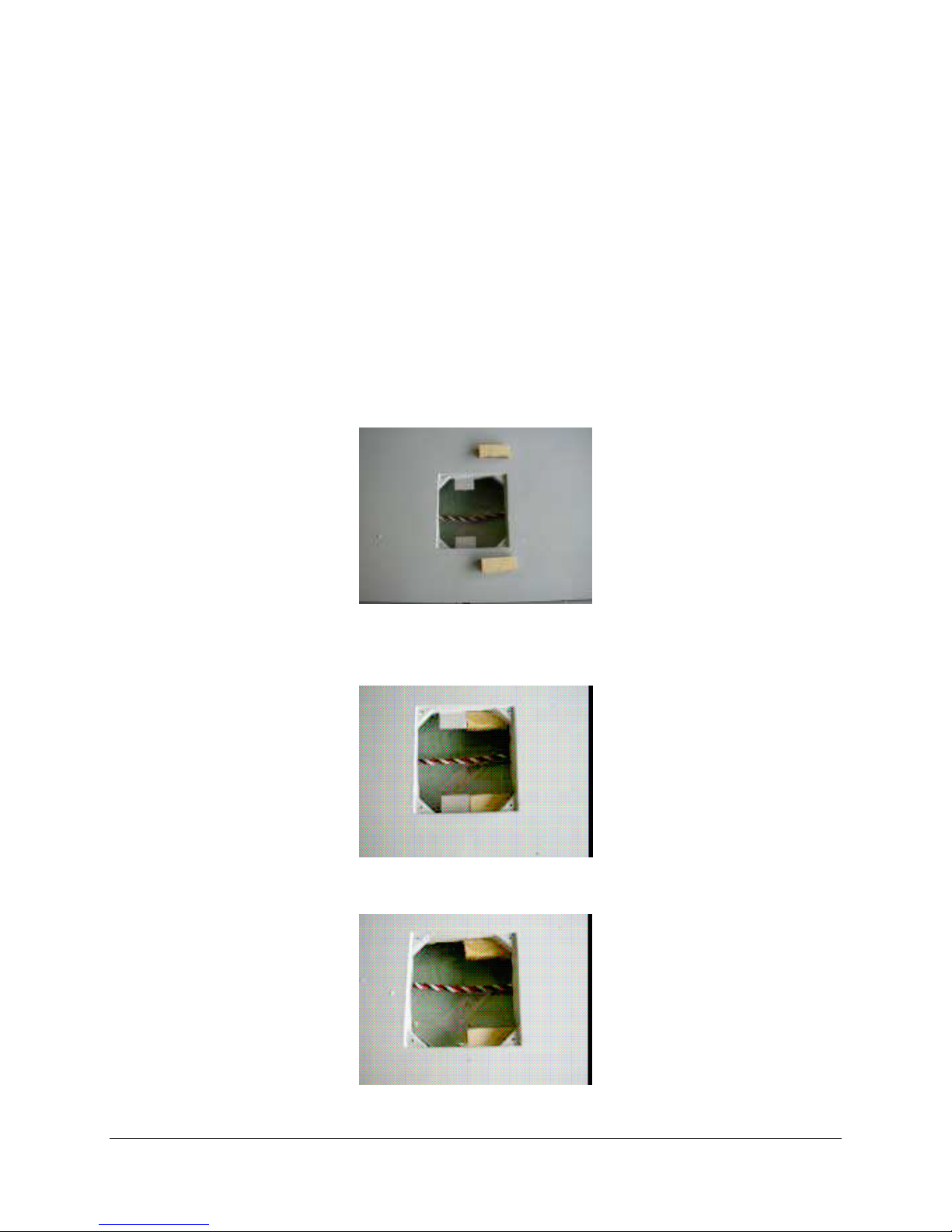
Place a wing on your towel to install the servos for the flaps and ailerons.
Fit the supplied aluminum mounts to the servo, using the supplied screws. Do not over tighten
and strip the screws. The screws appear to be smaller than the hole and strip easily. You may
need to get new screws if they strip. Do not use any grommets or other servo hardware.
As any play could cause flutter. Secure the screws with the medium strength blue thread
locktite.
Drill pilot holes in the wooden mounts and secure the servo with the kit-provided screws.
Do not over tighten and strip the screw holes. You may wish to strengthen the wooden threads by
unscrewing the screws and then putting a drop of thin CA in the holes then let it dry before you
screw the servos back in.
Page 18
F E I B A O F 1 8 - f
Repeat the last 8 steps for the flaps and ailerons when you are done mounting the servos.
You will need 12" extensions on the aileron servos. The flap servos, of course, only travel
17
down, so adjust your linkages and servos accordingly, so that they are all the way at one end
when the flaps are up(neutral, level with the wing), and all the way at the other end when flaps
are down. Note that you will need a servo reverse / programmer, a JR Matchbox, a reversed
servo, or two separate channels for normal setup of the flaps, or one will work backwards. If you
are using the now popular Spektrum DX7 radio, you will not have a spare channel to program
the second flap to move correctly. Here is a trick to allow you to run both flap servos off one
channel with just a regular servo y-harness.
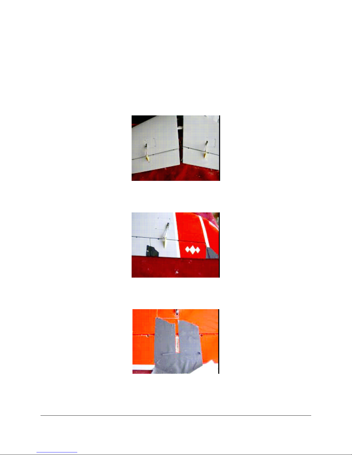
Install the flap servo into the right wing normally. For the left wing, do this: Cut two scrap
plywood blocks as shown, the same width as the existing servo mounts, but about 1" long.
Epoxy those blocks into place, level with the existing mounts. Do not epoxy them to the
mounts, but only to the wings and to the little corner triangular blocks that hold the servo cover
hold-down screws.
when the new blocks are thoroughly dry, cut away the old ones. A few strokes of a sharp
exacto will do it.
Trim the blocks for your servo. Make a cutout for the servo lead
Page 19
F E I B A O F 1 8 - f
18
Install the flap servo as shown, along with the linkage and horn. Note that they may not be
much structure beneath this new slot to hold the horn, pay extra attention to using lots of Hysol
or epoxy glue when you glue this horn in or you could use blocks that are bigger to go a bit
under the wing foil.
Now you have both flap servos facing the same direction and traveling the same way. After the
horns are glued in, you can plug both wings into a y-harness and adjust the linkages for matched
travel.
All of your servos are installed, now it is time to glue in the horns. Follow the same procedures
for all six horns. First use masking tape to tape the control surfaces to keep them from moving.
Surround each control horn slot with masking tape, leaving a 1/8" border all around. Do not
tape the area in front of the horn, only the two sides and the rear
Fill the slot completely with Hysol. Inject the glue as far in as you can go, it's much better to
have excess glue here than too little. This application is another great reason to use the Hysol
glue gun and nozzles; It is very difficult to get the glue down inside the slot without a glue gun.
19
Page 20

F E I B A O F 1 8 – f
Add a bead of glue to each side of the control horn. Be sure to use your nozzle to inject glue
into the small holes in the horn, they need to be filled with glue for proper strength of the joint.
Insert the control horn into the slot, making sure it is 90' to the surface, and not too deep and not too
shallow in the slot.
Smooth out the fillet of glue on each side of the horn with a dowel or your finger. If you do not
have a nice, complete fillet on both sides of the horn, add more glue until you do.
Remove the masking tape before the glue dries, and all the excess glue will go with it, leaving
you a nice 1/8" fillet around the horn.
Page 21

F E I B A O F 1 8 - f
This may not be necessary because of the epoxy glue used but just for security you can use
20
masking tape to hold the horn and linkage at 90' to the surface while drying.
Install the rudders with the supplied flat washers and hex 3mm bolts
For the flap and aileron servos you will need 12" extensions on the aileron servos. The flap
servos, of course, only travel down, so adjust your linkages and servos accordingly, so that they
are all the way at one end when the flaps are up(neutral, level with the wing), and all the way at
the other end when flaps are down. Note that you will need a servo reverse, a JR Matchbox, a
reversed servo, or two separate channels for normal setup of the flaps, or one will work
backwards. If you are using the popular Spektrum DX7 radio, you will not have a spare channel
to program the second flap to move correctly. Here is a trick to allow you to run both flap servos
off one channel with just a regular servo y-harness.
7: INSTALLING ORDNANCE ON WINGS
Using the supplied hardware, screw the wing tip missile holders in place then screw the
missiles in place, repeat this for the other wing.
Using the supplies hardware again screw on the drop tank / missile holders, they may be either
3mm thread or 4-40 threads depending on what the factory has in stock for blind nuts at the time
of making the wings. Take you time to check the threads before you mount the holders by gently
screwing in a 4-40 hex bolt first and if it is to loose then try a 3mm hex bolt.
Install them as the pictures shows. The missiles use self taping wood screws.
Page 22
F E I B A O F 1 8 - f
21
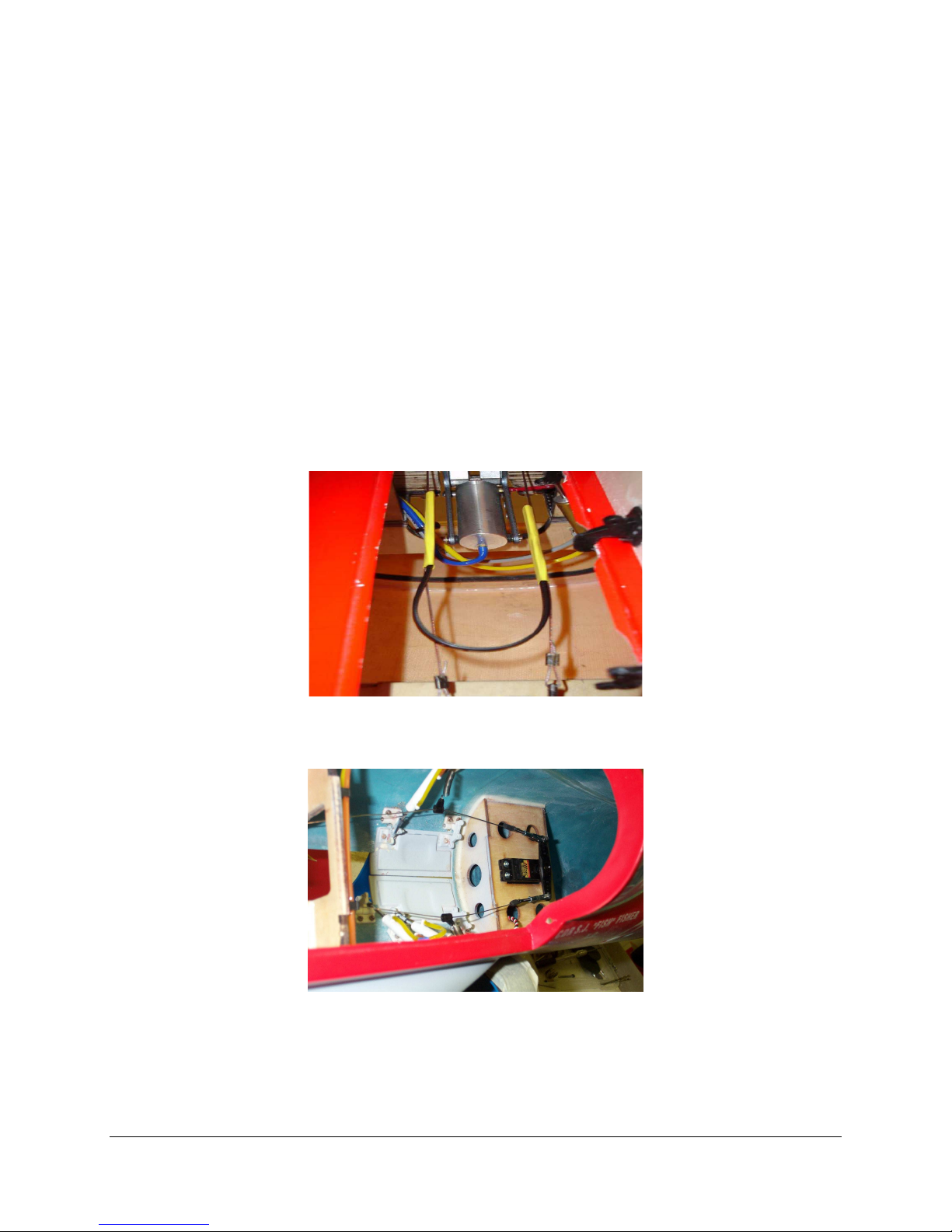
8: FRONT WHEEL SERVO & PULL-PULL LINKAGE
Install the nose gear steering servo with the hardware that is supplied with the servo
Use your hand pump to unlock the nose gear retract so it can move freely up and down. Insert
the nose gear assembly in the fuselage and check location and clearance in the fuselage.
There is a couple of ways in which you can spring the nose cables out of the way when the
gear retracts.
a) While rigging the cables of the nose gear steering, slide a length of heat shrink on to the cable
and continue with the normal setup of connecting the steering cables. Once the cables are
installed take a large zip tie and cut off the locking end. Slide each side of the cable tie into the
heat shrink and shrink them up, locking the tie to the cables. When the gear retracts the natural
spring action of the tie will spread the cables out of the way of the strut.
b) Use 2 Aileron Connectors and put them over each pull-pull cable before you crimp the ends on. You
want them in the middle area to pull the cable with a spring away from the steering strut. When it is in the
retract position.
Crimp the steering cables into place on the outer holes on the steering arm on the nose gear. Use a
double crimp, with the line going through the crimping tube twice.
Screw the nose gear assembly back into place on the mount.
Page 23
F E I B A O F 1 8 – f
22
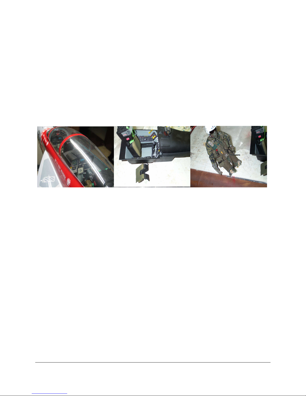
9: COCKPIT WITH PILOTS (OPTIONAL)
If you purchased the F18-f cockpit then you will need to also purchase some pilots. You can
put a couple George Bush 1/7 scale dolls in there but you will have to cut off the legs, and if you
get some F4 jet dolls then you will have to shorten there body and cut off there legs, Also the
bottom of the seat needs to be removed. Just look at the pictures below for clarification. You can
use some epoxy to secure them in after you check for clearance in the canopy.
You may have to trim the edges of the cockpit to get it to fit in the fuselage, try to have it just
sit on the indented edge so the canopy can keep it in place when installed. After you get a good
fit continue on with the pilots if you choose to do so.
10: PREPARING THE EQUIPMENT TRAY:
There are a number of different ways to setup your equipment tray including the air system, there are
fail-safe valves for the retracts, electronic valves that do not require a servo. The list can go on which is to
lengthy for us to review in this manual, so to keep it basic we will only install mainly the basics that come
with the combo package. The best thing to do is get every thing you are going to install in your model and
try to fit it on the tray first before you proceed, keeping in mind the Center of Gravity (CG). The batteries
are usually the last things to install and usually go in the nose but that would depend also if you are
installing the cockpit with Doll pilots or not.
One option is you could use one valve to operate the gears and the pneumatic brakes by the amount of
servo movement. Behotec sells this valve if you are going to be short on Radio channels. Also you could
use this same valve for the doors, retracts and brakes by having a stop valve that the retract touches when
it retracts. This stop valve only lets air pass through to close the doors after the retracts have retracted.
There is also a UP3 valve that has a delay valve in it for your doors. It is some times best to study what is
out there first before you proceed.
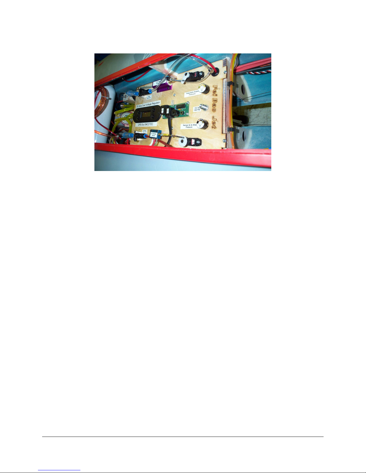
We will be using a UP3, a Proportional brake valve made by BVM and one of the valves that is
included in the combo package with 3 ports for the air brakes. If you are going to put in a cockpit then the
main tray will not give you very much room and it will be a lot easier if you put in another tray. The new
tray can be placed in front of the main fuel tank in the nose section like the next picture shows. You can
use 4 blocks on each corner of the tray and glue them to the fuselage then screw the tray in place after you
install every thing you want on it. Also making sure you mark the holes where the mounting screws go.
Page 24
F E I B A O F 1 8 – f
23
If you notice all the stuff on the main tray, it has been placed on the outer edges to prevent the
cockpit from touching them. The UP3, Receiver, Gyro and air failsafe are just under the main
tray in front of the UAT on the new made tray. You can see by the above picture the UAT, then
we put the fuel pump on one side and a smoke pump on the other side of the UAT, the ECU and
turbine valves are just behind the UAT.
Putting every thing in place so it all connects and works properly is the hardest part. So take
you time and try to plan it all out first before you start cutting holes in your tray, as was said
before neatness counts and is a must.
In the above picture it shows air tanks above the UAT. We had to exchange there place with
our batteries in the nose because of the extra weight from the cockpit with pilots. We had to
much weight forward and it was hard to get the proper CG.
11: INSTALLING EQUIPMENT TRAY
Cut out the servo holes. Depending on the type of wood tray you are using, It might be easy to
do with a few strokes of a new exacto knife or a cutting bit on a Dremel rotary tool.
Mount the servos in place using the hardware provided with the servos.
Make up some scrap plywood blocks for under your air valves. What you want to do is raise
the valves up so they are level with the servo arms, so that there are no side loads on the valves.
You want as straight as possible a link from the servos to the valves.
Drill holes through the blocks and the equipment tray and use 2-56 blind nuts under the tray to
secure the valves to the tray. Use 3/4” 2-56 screws to mount the valves in to the blind nuts on the
tray. You can use a little dab of epoxy or CA on the blocks to secure the blocks to the radio tray.
Notice how the valves are staggered to keep from hitting each other, and to keep the airlines
that will be attached from interfering with each other.
Page 25

F E I B A O F 1 8 – f
24
Link the valves to the servos using scrap pushrod wire.
Secure the fuel pump and smoke pump with a tie wrap next to the UAT You want the pumps
away from the receiver and ECU as far as possible to prevent any possible electronic interference
Connect the input side of the fuel pump to the UAT
Run the output side of the fuel pump to your manual shutoff valve and then to the fuel
solenoid.
Also Velcro is a really good way to attach some of your equipment, like the ECU, Receiver, air
failsafe and Gyro.
We used only one air fill valve as shown in the previous picture and then it “Y’s underneath to
one air gauge and then to a one-way check valve to the other air gauge this makes two separate
systems. Depending on were you wind up putting your air tanks just add a “Y” to that system
and put one tank to that system. This way if you had a leak you would still have the other system
working.
The small air gauges can be purchased from your dealer, that way you can see how much
pressure you have at all times. You can install them in the two holes provided already in the
main tray like is show in the previous picture. This location seems to be the best location as it
prevents interfering with the cockpit and also gives easy access to the filler valve.
After you are all done with your trays it is time to connect the forward and Aft fuselage
bulkheads together so you can finish connecting every thing to the trays.
12: CONNECTING FORWARD & AFT FUSELAGE
Make sure you have all the servo extensions from each servo and they are long enough after
you “Y” connect most of them to your receiver you could use tie’s or automotive spiro wrap to
help keep things neat and tidy.
Also if you notice in the picture we used a vodka bottle for our smoke fuel tank and put it on
top of the main tank.
25
Page 26

F E I B A O F 1 8 – f
After you know every thing is in place for aft fuselage then it is time to bolt the front of the
fuse to the Aft using 6 of the supplied 4mm bolts and also it is a good practice to use some blue
locktite on the threads first.
Now it is time to mount the trays in place, be extra careful not to pinch or kink any air lines or
extensions.
Check your pneumatic system for any leaks. Pump up the systems to approx. 100 psi. You
should be able to hold a full charge of air for days or even weeks. If you have any air bleeding
whatsoever, fix it now. You can try to spray a little Windex but you must dry it up a quick as
possible. Try to use a large gauge and some hemostats
by pinching off each section of airline, starting at the "outside" of the system by the retracts, and
testing each section one by one, until the leak or leaks are found.
Cut the tubing coming from the tank and connect it to the UAT , secure it with a tie wrap.
Cut the tubing coming from the smoke tank and connect it to the input of the smoke pump,
secure it with a tie wrap
Connect two high quality batteries to the regulators with switches you put on the tray before.
Wrap the batteries in foam and stuff them in the nose of the aircraft for now. Do not secure them
permanently yet, wait until you are ready to set the center of gravity.
Now is a good time to double check the installation of all servo extensions, airlines and turbine
electronics in and through the fuselage.
13: CARBON FIBER BYPASS, THRUST PIPE & ENGINE
Clean the fuselage thoroughly before installing the engine. If you need to trim the intake for
engine clearance, use a vacuum while you work. This will reduce the chance of having a foreign
object finding its way into your engine.
Test fit your turbine, check carefully for centering, and drill pilot holes for mounting screws.
Do not mount the turbine yet.
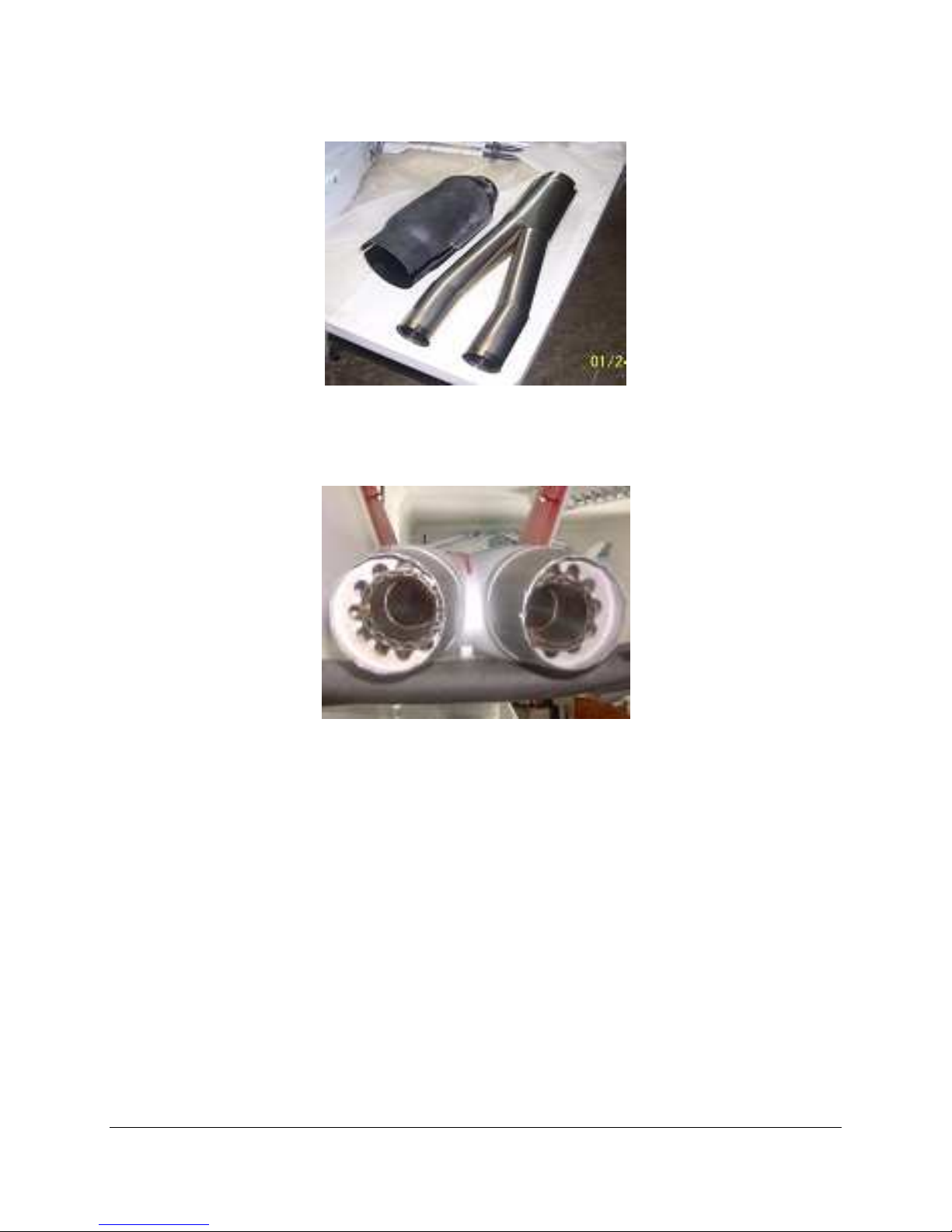
Drill two holes on each side of the thrust pipes mounting tabs. The first should be just in front
of the pipe mouth, the other approximately 50 mm further forward. Since the metal is very hard
stainless steal you should use a titanium or carbide bit to drill the holes.
The tabs are positioned just above the centerline of the pipe and this is the top. Insert the pipe
into the fuselage and position the aft end about 5 mm from the end of the exhaust cones.
26
Page 27
F E I B A O F 1 8 – f
You can either glue or use 4 to 6 small screws to mount each cone to the fuselage. Note the
arrows are on the tail cone formers, point them towards the center of the fuse, if not it will be
hard to fit the pipe, the holes are on a offset in the cones.
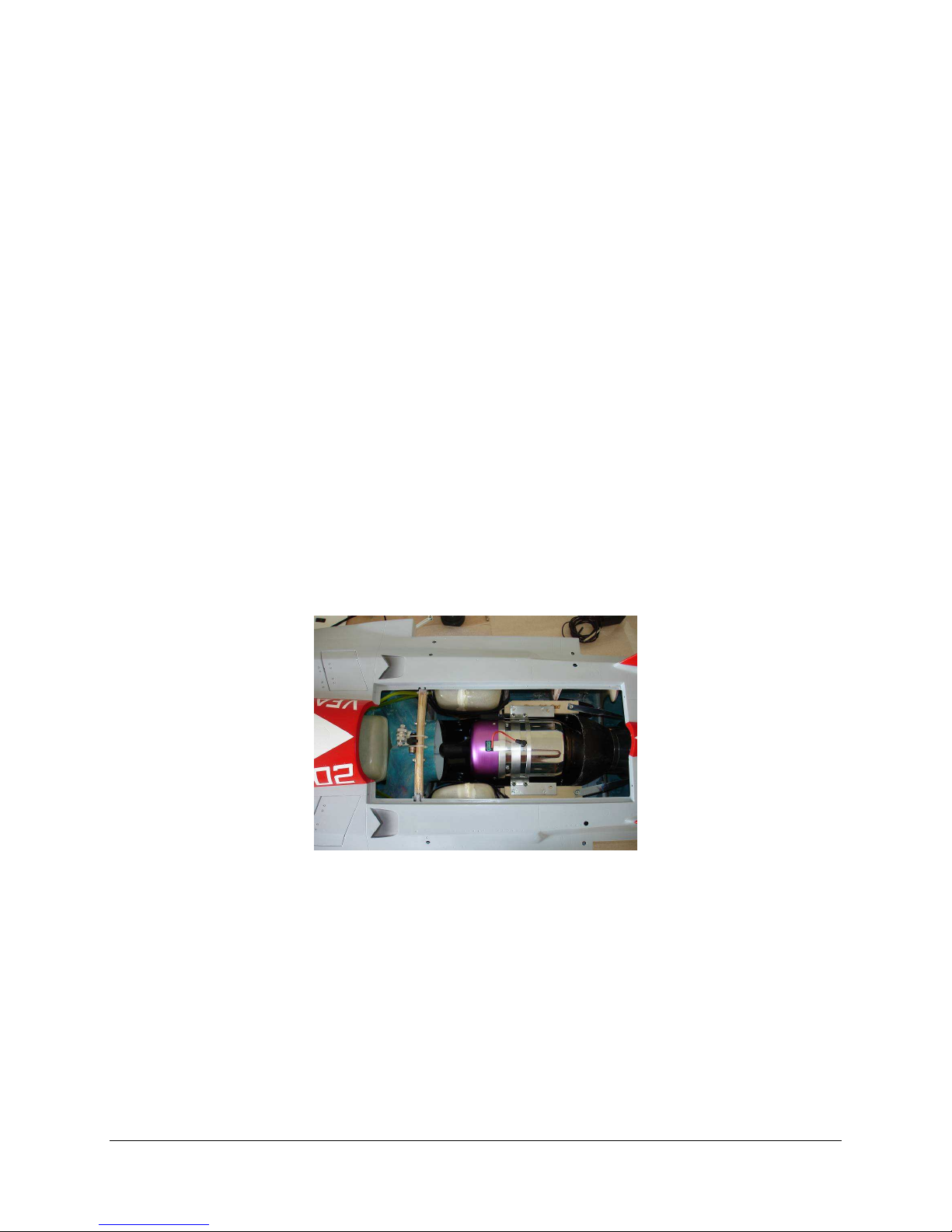
Place the lower bypass on the engine mounting rails. Slip the pipe forward over the aft end of
the bypass.
Position your engine on the mounting rails. Set the gap between the rear of the exhaust cone
and the mouth of the pipe to manufacturers specifications. This is usually around 20 mm. You
may need to trim some material off the intakes to allow the engine to sit far enough forward.
If required, marks the bypass for the positions of the engine mounting tabs and trim away
material such that the engine exhaust is centered on the pipe. Shims may be required under the
front engine-mounting tab to insure that the angle of the engine is on line with the angle of down
thrust of the pipe.
When you are satisfied, bolt the engine to the side frames with either blind nuts or
appropriately sized wood screws, if the later is preferred. Install the screws and then remove.
Coat the threaded holes with thin CA. This will harden the wood around the screw holes
themselves. Permanently reinstall the engine mounting screws.
Page 28
F E I B A O F 1 8 – f
27
Drill and secure the bypass to the engine mounting rails with four wood screws.
Finally, drill the rear of the bypass for the pipe mounting straps and bolt in place. The heads of
the bolts should be on the inside of the bypass.
Drill a hole where the lines and wires need to go through to the turbine. The hole needs to be
large enough to accommodate any connectors on any leads coming from your turbine. About one
inch in diameter will do for the Multiplex connectors used on most engines.
Take a scrap piece of airline tubing about four inches long. Cut a slice on the side of it with a
sharp razor, and fit it around the edges of the hole you made, and CA it into place. This will
serve as a grommet to keep the sharp edges of the fiberglass hole from cutting your wiring and
tubing.
Remove the plates. Put a fuel proof finish on them in case of fuel spills.
Remount the plates with all six screws and tighten firmly.
Put all your turbine wire leads and tubes through the hole you made and mount the turbine
with four screws.
Connect fuel, gas and electrical lines up to the turbine
.
Test fit the Carbon fiber bypass cover, mark and cut or drill a hole if needed for the glow plug
or kero start plug.
Mount the carbon bypass engine cover with four screws.
14: CG (CENTER OR GRAVITY), BATTERIES & AIR TANKS
Fit the wings into place. Connect up the extensions for the ailerons and flaps.
Tuck the excess cable back into the wing, not the fuselage.
Secure the wings into place and tighten the 4 hex bolts for each wing
Page 29

F E I B A O F 1 8 – f
28
Place your ECU and Radio batteries in the nose for now. Do not secure them yet. You will
need to move them either forward or Aft to achieve the recommended CG. Once the balance is
properly achieved and the batteries can be installed in the nose you might want to get a piece of
aluminum flat bar to dissipate any heat then bend the rear of aluminum 90 degrees to butt it up to
front former and secure with a bolt and wing nut for easy removal for recharging or you could
just mount them to the fuselage with heavy duty Velcro.
Congratulations, you have now completed construction of your F18-f.
The next step is programming your transmitter, and setting the servo throws.
See the Technical Data next for balance and control throws.
TECHNICAL DATA:
Length: 90"
Wingspan: 67"
Dry Weight: 26 lbs
Fuel Capacity: 168 oz or 5.25 Liters, not including UAT
Servos used:
Flaps------(2) 5955TG
Ailerons---(2) 5245mg
Rudders--- (2) 5125mg
Steering---(1) 5955TG
Elevators---(2) 5955TG
Valves---(3) HS81mg
Recommended CG should be 5” to 6” from the wings leading edge and for the first maiden flight
a good starting point would be 5”
Balance with tanks empty and UAT full also landing gear up.
Control Throws
These are good place to start.
Aileron: 1/2” to 5/8” up and down
Elevator: 1-1/2” to 1-7/8” up and down
Rudders: 1/2” to 5/8” right and left
Flaps: Take off 3/4” to 1” down, Landing 2-1/8” to 2-3/8” down
You may want an up-elevator mix with flap application, as the nose pitches down. You may also
want some additional up-elevator throw available with full flaps, as you may not have enough
elevator to flare with full flaps. A "landing" mix will reduce the pilot workload. These settings, flapto-elevator, will change if you move the CG back. You can also increase the rudder throw, to allow
for straighter knife edges.
Page 30

F E I B A O F 1 8 – f
Credits:
Written by Jeff DeCaluwe
Test Pilot: Peter Doupnik
Maiden
at Leamington Airport, Ontario, Canada
29
NOTES!______________________________________________________________________________________
_____________________________________________________________________________________________
_____________________________________________________________________________________________
_____________________________________________________________________________________________
_____________________________________________________________________________________________
_____________________________________________________________________________________________
_____________________________________________________________________________________________
_____________________________________________________________________________________________
_____________________________________________________________________________________________
_____________________________________________________________________________________________
_____________________________________________________________________________________________
_____________________________________________________________________________________________
_____________________________________________________________________________________________
_____________________________________________________________________________________________
_____________________________________________________________________________________________
_____________________________________________________________________________________________
_____________________________________________________________________________________________
_____________________________________________________________________________________________
_____________________________________________________________________________________________
_____________________________________________________________________________________________
_____________________________________________________________________________________________
_____________________________________________________________________________________________
_____________________________________________________________________________________________
_____________________________________________________________________________________________
_____________________________________________________________________________________________
_____________________________________________________________________________________________
_____________________________________________________________________________________________
_____________________________________________________________________________________________
_____________________________________________________________________________________________
_____________________________________________________________________________________________
_____________________________________________________________________________________________
_____________________________________________________________________________________________
_____________________________________________________________________________________________
_____________________________________________________________________________________________
_____________________________________________________________________________________________
_____________________________________________________________________________________________
_____________________________________________________________________________________________
_____________________________________________________________________________________________
_____________________________________________________________________________________________
_____________________________________________________________________________________________
_____________________________________________________________________________________________
30
Page 31

 Loading...