

Feeney DesignRail Installation Instructions Manual
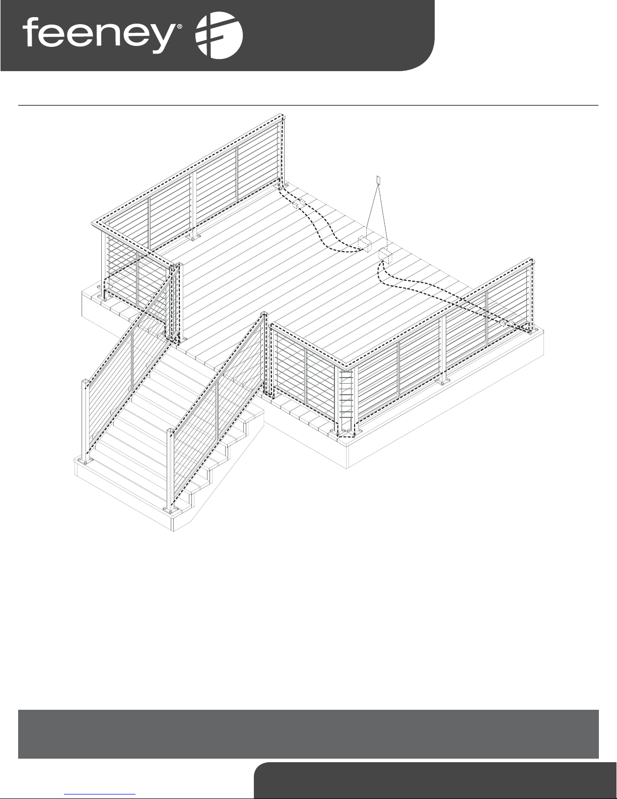
Installa on Instruc ons
for DesignRail® 24VDC LED Ligh ng
Drivers are available in a variety of wa ages. In general a driver should not exceed more than 80% of its rated wa age.
(Example: 60W Driver = 60 x 0.8 = 48W Max).
Strip Lights require 1.44 wa s per foot. A er determining the necessary length of strip ligh ng, calculate the wa age and ensure the
driver being used has adequate capacity. (Example: 10’ = 10 x 1.44 = 14.4W)
The maximum length of strip ligh ng that can be connected in one run is 25 feet. If one sec on of ligh ng is longer than 25 feet, it
must be broken into mul ple smaller sec ons and run on separate circuits.
Building codes vary by loca on and jurisdic on. Consult all applicable codes before installing DesignRail® LED Ligh ng.DesignRail®
LED Ligh ng may not be suitable for every applica on and it is the sole responsibility of the installer to ensure that DesignRail® LED
Ligh ng is used for its intended purpose.
WARNING: ELECTRIC SHOCK IS ALWAYS POSSIBLE WHEN WORKING WITH ELECTRICITY. THIS CAN CAUSE SERIOUS PERSONAL
INJURIES OR DEATH. ELECTRICAL SHORTS CAN ALSO CAUSE FIRES AND PROPERTY DAMAGE. ALWAYS MAKE SURE THE
ELECTRICAL OUTLET YOU ARE PLUGGING INTO IS GROUNDED.
1-800-888-2418 | www.feeneyinc.com 1
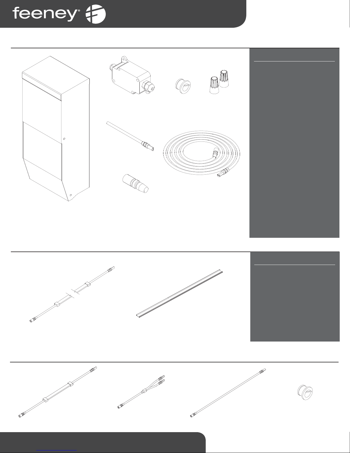
Power Kits - Package Contents
COMMERCIAL GRADE
WET LOCATION
MINI JUNCTION BOX
(SKU #7680)
SOLDER CONNECTOR (UL)
(MALE ONLY)
(SKU #7673)
ISOLATION
BUSHING
(SKU #1114)
WIRE NUTS
(PAIR)
(SKU #7670)
POWER KIT OPTIONS
SKU #7683 - 96w Power Kit
1x 96w Dimmable Driver
2x Mini Junc on Box
2x 11' Extension Cable
2x Wire Nuts
2x Solder Connector
2x Isola on Bushing
2x Terminator Cap
SKU #7682 - 60w Power Kit
1x 60w Dimmable Driver
2x Mini Junc on Box
2x 11' Extension Cable
2x Wire Nuts
2x Solder Connector
2x Isola on Bushing
2x Terminator Cap
(Pair)
(1114)
(Pair)
(1114)
TERMINATOR CAP
(FEMALE ONLY)
24V MAGNETIC DIMMABLE DRIVER
(SKU # VARIES BY WATTAGE)
(SKU #7671)
Light Kits - Package Contents
LED LIGHT STRIP (UL)
(SKU # VARIES BY LEGNTH)
11' EXTENSION CABLE (UL)
(SKU #7650)
48" FROSTED
DIFFUSER LENS
(SKU #7662)
SKU #7681 - 40w Power Kit
1x 40w Dimmable Driver
1x Mini Junc on Box
1x 11' Extension Cable
1x Wire Nuts
(Pair)
1x Solder Connector
1x Isola on Bushing
(1114)
1x Terminator Cap
LIGHT KIT OPTIONS
SKU #7653 - 32" LED Kit
1x 32" LED Light Strip*
1x 48" Frosted Diff user Lens
SKU #7652 - 20" LED Kit
1x 20" LED Light Strip*
1x 48" Frosted Diff user Lens
*All Light Strips are 3000K/24V
Addi onal Items
4" LED LIGHT STRIP (UL)
(SKU #7684)
1-800-888-2418 | www.feeneyinc.com2
2 WAY WATERPROOF
SPLITTER (UL)
(SKU #7668)
12" EXTENSION CABLE (UL)
(SKU #7719)
40" EXTENSION CABLE (UL)
(SKU #7669)
ISOLATION BUSHING FOR
BOTTOM RAIL/100 SERIES
LIGHTING
(SKU #1114)
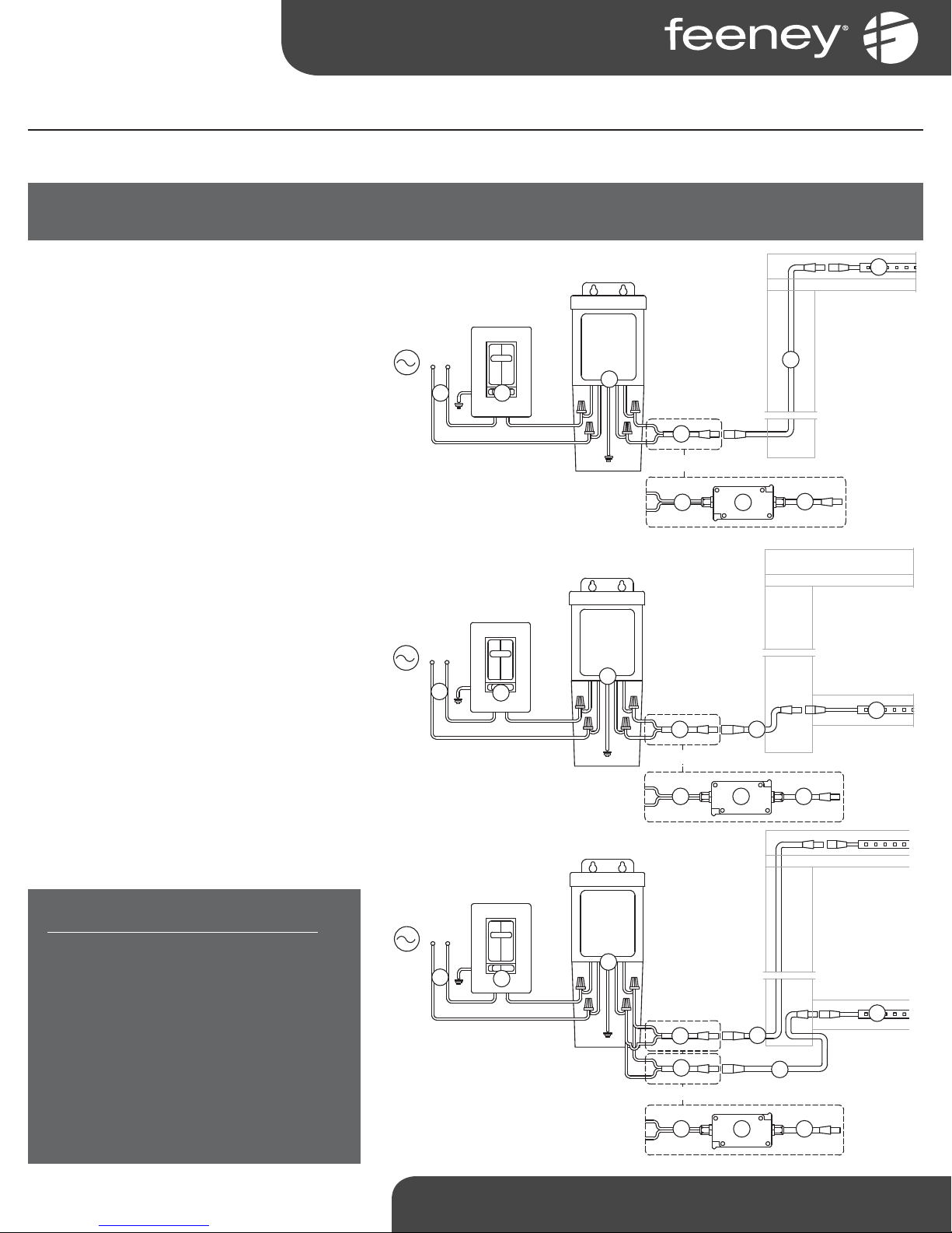
Power Kits - Installa on
Step 1 – Connect Source Power to Driver
IMPORTANT SAFETY NOTE: TO REDUCE RISK OF ELECTRICAL SHOCK, TURN OFF AC CIRCUIT BREAKER PRIOR TO COMMENCING ANY ELECTRICAL WORK AND
CONNECTING DRIVER(S) TO AC POWER SOURCE. VERIFY THAT LIVE POWER IS NOT PRESENT AT JUNCTION BOX WHEN MAKING CONNECTIONS.
Determine loca on of driver.
Note: It is best to locate the drivers as close as
possible to the lighࢼ ng to reduce the possibility
of voltage drop occuring. If possible, the driver
enclosure should be within 5 feet of the post that
will accept the 11' extension cable, acࢼ ng as the
lead wire to the fi rst strip light. If necessary, up
to 30 feet of 14 AWG wire can be used between
the driver and the 11' extension cable.
Route exterior rated wiring from compa ble
dimmer switch/AC power source to loca on of
driver.
Connect drivers to dimmer switch/AC power
source using wire nuts.
Connect 11' extension cable(s) and route outside
of driver to post.
If necessary, run up to 30 feet of 14 AWG wire
to a wet-loca on mini junc on box and transi -
on to solder connector.
TOP RAIL LIGHTING - WIRING DIAGRAM
3
1 2
BOTTOM RAIL LIGHTING - WIRING DIAGRAM
3
1
2
6
OR
4
6
8
7
5
6
8
7
LIGHTING COMPONENTS
1. Power (by customer)
2. Light Switch (by customer)
3. 24v Dimmable Driver
1
2
4. 14 Gauge Wire (by customer)
5. Mini Junc on Box
6. Solder Connector
7. 11' Extension Cable
8. LED Light Strip
1. Mount ver cally only. See Switch Compatabilty Spec Sheet at
www.feeneyinc.com
2. See Driver Spec Sheet at www.feeneyinc.com
OR
4 6
TOP & BOTTOM RAIL LIGHTING - WIRING DIAGRAM
5
3
1
2
6
6
OR
4 6
Note: If using both top and bo om rail lighࢼ ng, run each on their own circuit.
7
7
5
1-800-888-2418 | www.feeneyinc.com 3
8
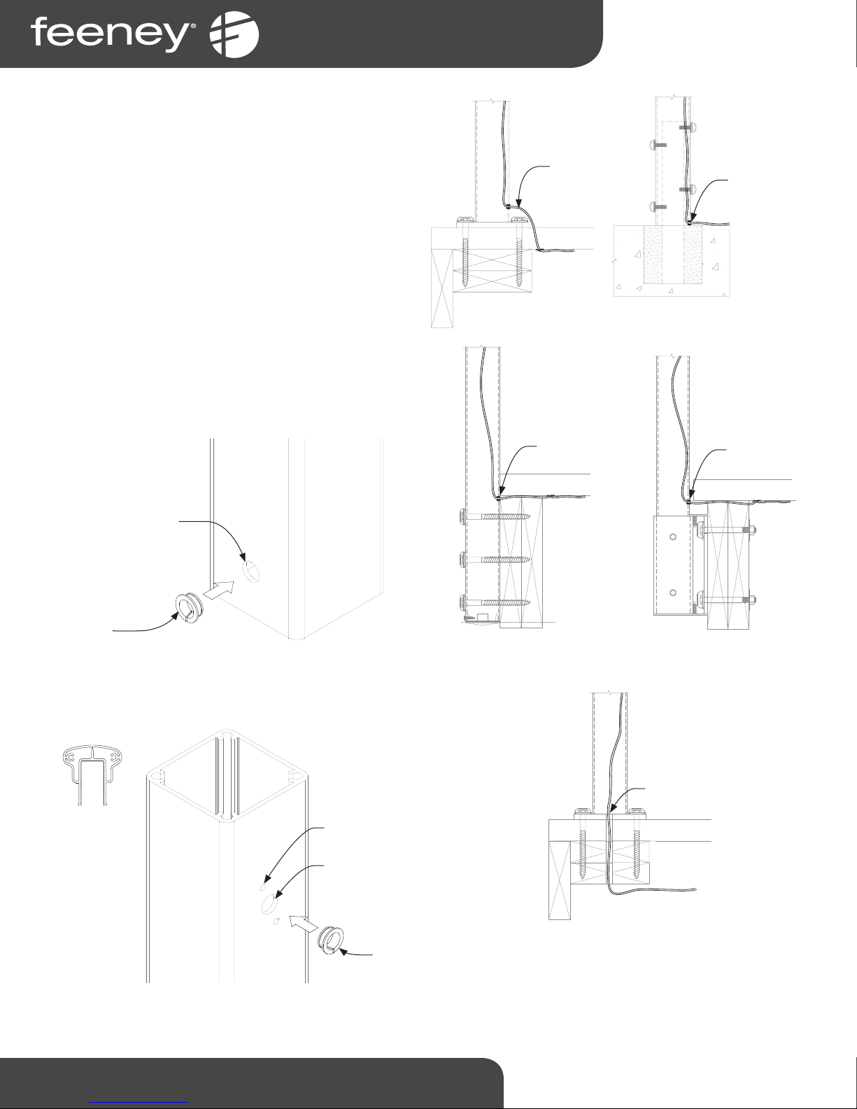
STEP 2 - DRILL POSTS AND ROUTE LEAD WIRE
Note: Running the lead wire through the post is easier when done
prior to mounࢼ ng post.
Determine loca on that lead wire will enter post.
Note: Depending on the post mounࢼ ng method, and enclosure
locaࢼ on relaࢼ ve to the post, the lead wire entrance point may
vary. (See Figure 1.2 for typical recommendaࢼ ons)
Drill 1/2” diameter hole in post at desired lead wire entrance
loca on and insert supplied grommet, part #1114. (See Figure 1.1)
For Series 150: drill a 1/2” diameter hole ver cally centered
between the top RCB holes and insert supplied grommet (See
Figure 1.3).
the RCB hollow. Repeat this step for each post which will have
light strips running through it.
This will allow the light strip wiring to pass through
WIRE COMES
UP THROUGH
DECKING AND
INTO POST.
WIRE RUNS UNDER
DECK THROUGH
FASCIA BOARDS
AND ENTERS POST
BELOW DECKING
DURFACE BETWEEN
FACSIA AND POST
FACE.
WIRE CAN BE RUN
IN CONDUIT BURIED
IN CONCRETE, OR
RUN DIRECTLY
FROM ENCLOSURE
TO POST. WIRE
INSIDE POST RUNS
BETWEEN INSIDE
POST WALL AND
STANCHION.
WIRE RUNS
UNDER DECK AND
ENTERS POST
ABOVE FASICA
BRACKET BELOW
DECKING.
GROMMET
PAR T # 1114
SERIES 150
1/2" DIA.
HOLE
Figure 1.1
SERIES 150 TOP RAIL
RCB SCREW HOLES
1/2" DIA. HOLE (CENTER
BETWEEN RCB HOLES)
WIRE RUNS UNDER
DECK THROUGH 3/4"
HOLE IN BASEPLATE
AND BLOCKING.
(3/4" HOLE DRILLED BY
CUSTOMER)
Figure 1.3
1-800-888-2418 | www.feeneyinc.com4
GROMMET
PAR T # 1114
Figure 1.2
 Loading...