

Feelsafe OMNI 3000 Programming Instructions Manual
0
tructions
SEPT '86.
F&Safe, Inc., 50 Engineers Road, Houppauge. New York 11788
(516) 5826161
(803) 6455430
Copyright @ ‘85 FeelSafe. Inc.
Printed in U S.A.’
; r;
’ 4’
.
.
..’ Many of-the panels functions including zone types and operations, audible or silent outputs.,
etc. are prom programmable.
Therefore, it is imperative that these instructions are read
and followed very carefully.
Many of the options available will require programming in
several different locations of different fields.
It is advisable to utilize the BLANK
PROGRAMMING SHEET MARKED WITH-LOCATIONS (Ll, L2, etc.) to write out the entire
program before attempting to actually program.
The first and MOST IMPORTANT decision
which must be made prior to programming is what each of the 12 general purpose zones are
planned to be.
There are several options such as 24 HR ALARM ZONES, 24 HR TROUBLE
ZONES, or CONTROLLED ZONES (Delay, Instant, Interior).
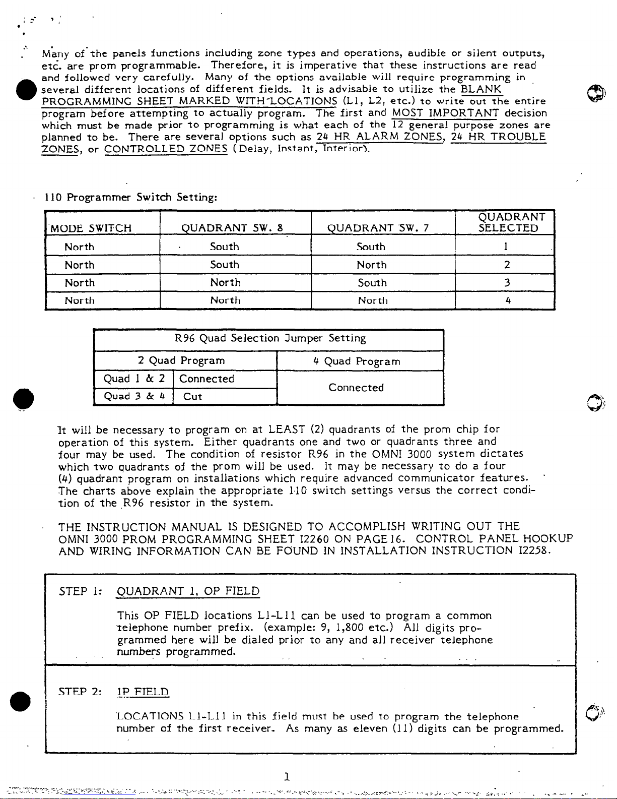
110 Programmer Switch Setting:
.
‘MODE SWITCH
QUADRANT SW. 8
North
South
North
South
North
North
North
North
,
QUADRANT SW. 7
South
North
South
North
QUADRANT
SELECTED
1
2
3
4
I
R96 Quad Selection Jumper Setting
1
2 Quad Program 4 Quad Program
Quad 1 h 2 Connected
Connected
Quad 3 & 4 cut
,
It will be necessary to program on at LEAST (2) quadrants of the prom chip for
operation of this system.
Either quadrants one and two or quadrants three and
four may be used.
The condition of resistor R96 in the OMNI 3000 system dictates
which two quadrants of the prom will be used.
It may be necessary to do a four
(4) quadrant program on installations which require advanced communicator features.
.
The charts above explain the appropriate 1210 switch settings versus the correct condition of the .R96 resistor in the system.
THE INSTRUCTION MANUAL IS DESIGNED TO ACCOMPLISH WRITING OUT THE
OMNI 3000 PROM PROGRAMMING SHEET 12260 ON PAGE 16. CONTROL PANEL HOOKUP
AND WIRING INFORMATION CAN BE FOUND IN INSTALLATION INSTRUCTION 12258.
STEP 1:
QUADRANT 1, OP FIELD
This OP FIELD locations Ll-Lll can be used to program a common
telephone number prefix.
(example: 9, 1,800 etc.) All digits pro-
grammed here will be dialed prior to any and all receiver telephone
. .
numbers programmed.
.
STEP 2:
L! FIELD
‘LOCATIONS Ll-Lll in this field must be used to program the telephone
number of the first receiver- As many as eleven (11) digits can be programmed.
I
, STEP 3: 2P FIELD
.
LOCATIONS Ll-Lll can be used to program the telephone number of the
second receiver.
As many as eleven (11) digits can be programmed. If
there is no second receiver, leave this field blank on
the
program sheet.
STEP 4:
3P FIELD
LOCATIONS Ll-Lll can be used to program the telephone number of
receiver three.
As many as eleven (11) digits
can be programmed.
If
there is no third receiver, leave this field blank on the program sheet.
STEP 5:
AF FIELD
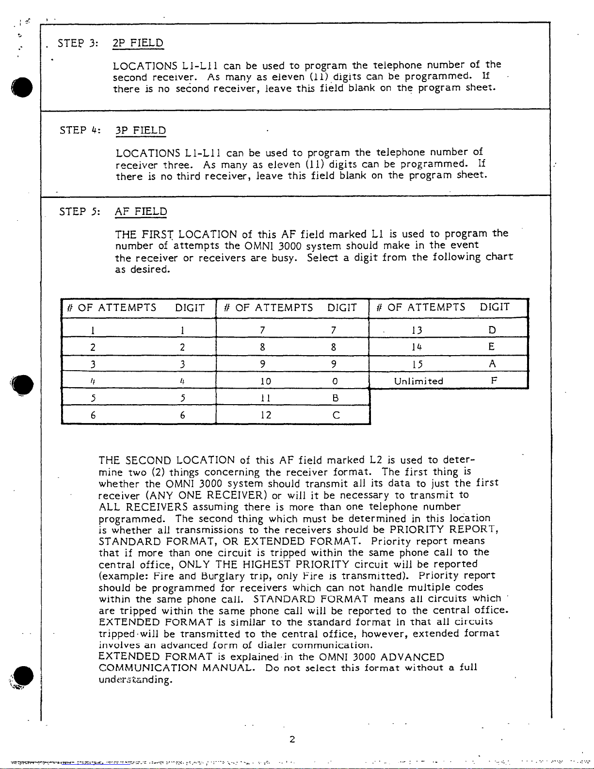
THE FIRST LOCATION of this AF field marked Ll is used to program the
number of attempts the
OMNI 3000
system should make in the event
the receiver or receivers are busy.
Select a digit from the following chart
as desired.
.
// OF ATTEMPTS
DIGIT // OF ATTEMPTS DIGIT
# OF ATTEMPTS DIGIT
1 1
7 7 13
D
2 2
8 8 14
E
3
3
9 9
15
A
4 4
10 0
*
1
Unlimited
F
5 5
I1 B
1
6 6
12 C
THE SECOND LOCATION of this AF field marked L2 is used to determine two (2) things concerning the receiver format. The first thing is
whether the
OMNI 3000 system should transmit all its data to just the first
receiver (ANY ONE RECEIVER) or will it be necessary to transmit to
ALL RECEIVERS assuming there is more than one telephone number
programmed.
The second thing which must be determined in this location
is whether all transmissions io the receivers should be PRIORITY REPORT,
STANDARD FORMAT, OR EXTENDED FORMAT. Priority report means
that if more than one circuit is tripped within the same phone call to the
central office, ONLY THE HIGHEST PRIORITY circuit will be reported
(example: Fire and Burglary trip, only Fire is transmitted). Priority report
should be programmed for receivers which can not handle multiple codes
within the same
phone
call. STANDARD FORMAT means all circuits which
are tripped within the same phone call will be reported to the central office.
EXTENDED FORMAT is similar to the standard format in that all circuits
tripped.will be transmitted to the central office, however, extended format
involves an advanced form of dialer communication.
EXTENDED FORMAT is explained.in the
OMNI 3000 ADVANCED
COMMUNICATION MANUAL. Do not select this format without a full
underz&nding.
2
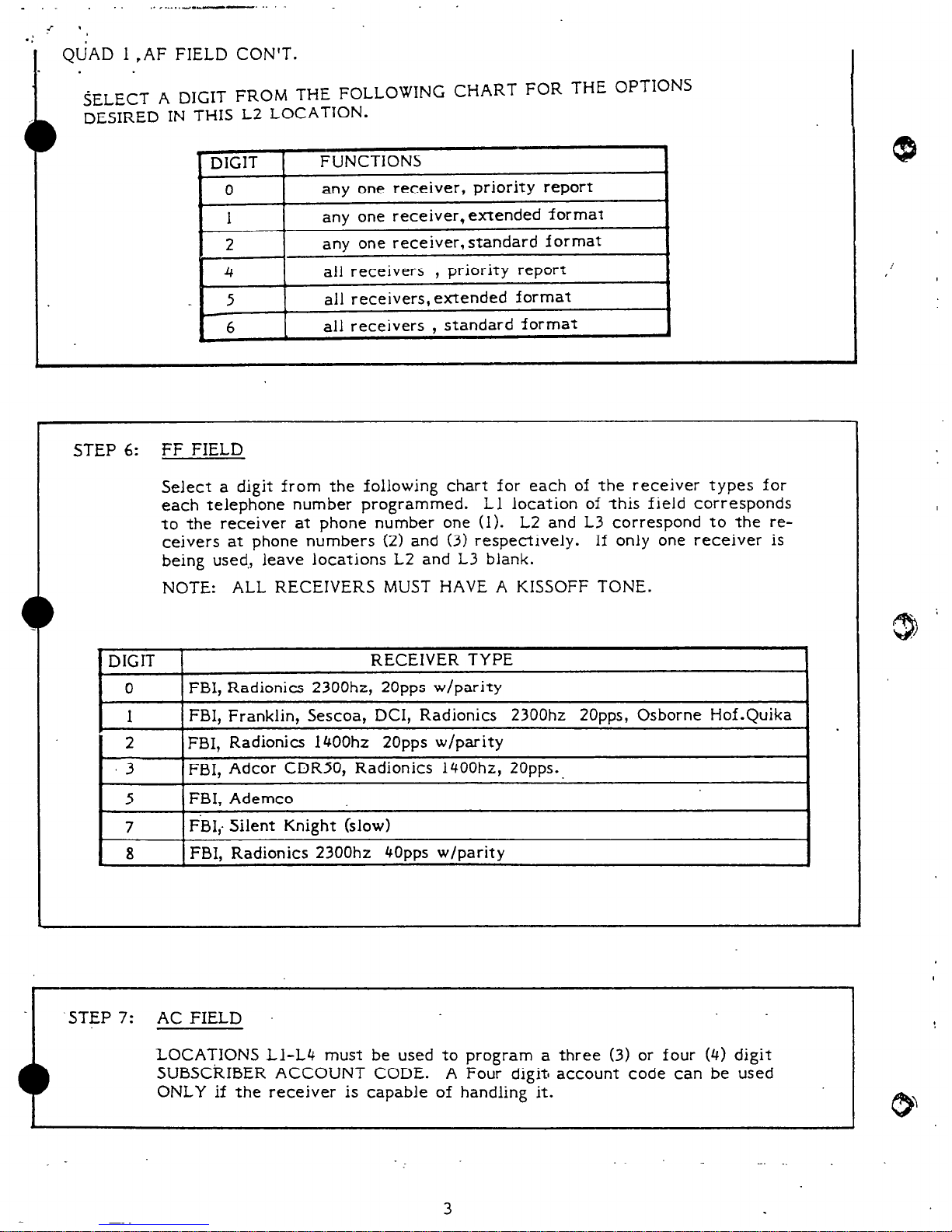
QUAD 1 ,AF FIELD CON’T.
SELECT A DIGIT FROM THE FOLLOWING CHART FOR THE OPTIONS
DESIRED IN THIS L2 LOCATION.
.
DIGIT
0
1
b
2
4
5
1 6
f
FUNCTIONS
any one receiver, priority report
any one receiver, extended format
any one receiver, standard format
all receivers , priority report
all receivers, extended format
all receivers ,
standard format
,
STEP 6:
FF FIELD
Select a digit from the following chart for each of the receiver types for
each telephone number programmed. Ll location of this field corresponds
to the receiver at phone number one (1).
L2 and L3 correspond to the receivers at phone numbers (2) and (3) respectively. If only one receiver is
being used,, leave locations L2 and L3 blank.
NOTE: ALL RECEIVERS MUST HAVE A KISSOFF TONE.
DIGIT
RECEIVER TYPE
0
FBI, Radionics 2300hz, 2Opps w/parity
1
FBI, Franklin, Sescoa, DCI, Radionics 2300hz 2Opps, Osborne Hof.Quika
2 FBI, Radionics 1400hz 2Opps w/parity
3 FBI, Adcor CDRSO, Radionics 1400hz, 20~~s..
5
FBI, Ademco
7
FBI,- Silent Knight (slow)
8
FBI, Radionics 2300hz 4Opps w/parity
.STEP 7:
C’
AC FIELD
LOCATIONS Ll-L4 must be used to program a three (3) or four (4) digit
SUBSCRIBER ACCOUNT CODE. A Four digit account code can be used
ONLY if the receiver is capable of handling it.
J
I
-.
3

STEP 8: AL FIELD
This AL field locations Ll-Lll must be used to program the DESIRED ALARM
CODES for all zones listed from the chart below in all the respective locations.
Zones one (1) through five (5) can all be. programmed to report separate alarm
codes. Zones six (6) through twelve (12) will ALL REPORT THE SAME ALARM
CODE. Program an (F) in the locations of all zones which are NOT desired to
transmit to the central office.
Program an (F) in the respective locations of all
zones which will be programmed as 24 HR. TROUBLE ZONES. Program location
Lll, (F) until reading the ADVANCED COMMUNICATION MANUAL.
LOCATION DESCRIPTION
CODE
_ -... _
Ll
Keypad AMBUSH
o-9
L2
Keypad PANIC
o-9
L3
Keypad Medical o-9
L4
Fire Zone Alarm Code
o-9
LS
Zone 1 Alarm Code
o-9
L6
Zone 2 Alarm Code
o-9
L7
Zone 3 Alarm Code
o-9
L8 Zone 4 Alarm Code
o-9
L9
Zone 5 Alarm Code
o-9
110
Zone 6- 12 Alarm Code o-9
Lll
Always F
Always F
QUADRANT ONE HAS BEEN SUCCESSFULLY FILLED OUT AT THIS POINT.
Step 9:
QUADRANT 2, OP FIELD
This OP Field Quadrant two (2) can be used to program several of the
communicator codes including CLOSING/OPENING, ZONE BY PASS/TROUBLE,
and THE COMMON TROUBLE CODE. The closing/opening codes which are
programmed here will be reported when ANY of the eight (8) Users of this
system ARM/DISARM. The Zone Bypass/Trouble codes which are programmed.
in locations L4-L8 for zones one (1) through five (5) can actually be two different things depending on the zone types.
If any of zones one (1) through five. _
(5) -are programmed to be burglary zones, (delay, instant, interior) these codes
will be reported to the central office as BYPASS CODES. If any of zones
ttio (2) through four (4) have been programmed as 24 HR. TROUBLE ZONES,
these codes will represent the actual ALARM CODES for those zones.
Program’
an (F) in the L9 location of this field because zones six (6) through twelve (12)
cannot transmit a bypass code.
Program a code in the LlO location that will be
transmitted whenever the COMMON TROUBLE ZONE senses a violation. The
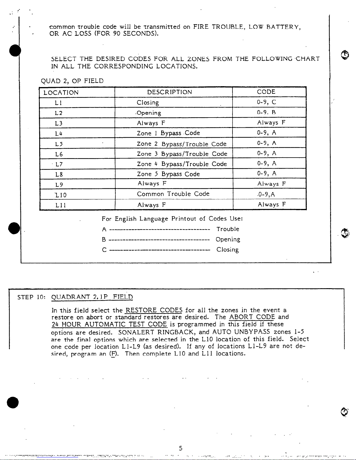
common trouble code will be transmitted on FIRE TROUBLE, LOW BATTERY,
OR AC LOSS (FOR 90 SECONDS).
SELECT THE DESIRED CODES FOR ALL ZONES FROM THE FOLLOWING CHART
IN ALL THE CORRESPONDING LOCATIONS.
QUAD 2, OP FIELD
For English Language Printout of Codes Use:
A _- ______ - ________________________
Trouble
B
___--------------------------------
Opening
C
--- ___- - ___________ - _____ -
Closing
I
STEP 10: QUADRANT 2,1 P FIELD
In this field select the RESTORE CODES for all the zones in the event a
restore on abort or standard restores are desired. The ABORT CODE and
24 HOUR AUTOMATIC TEST CODE is programmed in this field if these
ootions are desired. SONALERT RINGBACK, and AUTO UNBYPASS zones l-5
are the final options which .are selected in the LlO location of this field. Select
one code per location Ll-L9 (as desired).
If any of locations Ll-L9 are not de-
sired, program an (E).
Then complete LlO and Ll 1 locations.
_
. .
 Loading...