

Page 1
FeelChip-D Manual
Maurice Op de Beek
version 1 , 20190607
Page 2

Table of Contents
Introduction 3
Programming 4
Tag-Connect PCB Pads 4
Board Overview TOP 5
TOP Parts 6
TOP Pads 7
Board overview BOTTOM 8
BOTTOM Parts 9
BOTTOM Pads 9
USB Battery Charger 10
LDO Power 10
Battery power 10
DC motor 10
FCC information 11
Page 3

Introduction
The FeelChip D is PCBA board designed for the haptic industry. It has 3 motor channels and
5 touch channels. The FeelChip D is equipped with:
1. a LIPO charging unit
a. 5 volt
2. RGB LED light
a. Charging (red)
b. Almost empty (blinking red)
c. Bluetooth (blue)
d. Charged (green)
3. Press Button
a. Turn the device on/off
b. Switch through patterns
4. Programmer
a. Pin to program the ESP32
5. MPR121
a. ReceiPintove up to 5 capacitive touch inputs
6. Bluetooth and Main processor (Espressif ESP32)
a. Get firmware version
b. Get hardware version
c. Get battery level
d. Control up to 1 to 3 motors
e. Read up to 5 touch sensors
Page 4
Programming
The FeelChip-D-2p can be programmed with a Tag connect TC2030-IDC-NL or a
1
TC2030-MCP-NL on the small footprint PCB Tag-Connect PAD. Alternatively it can be
2
programmed using the test pads with the aid of a Pogo Pin test setup.
There are two methods to programming the FeelChipD:
,
1) Via Tag-Connect PCB pads
2) Via Pogo-Pin Test pads
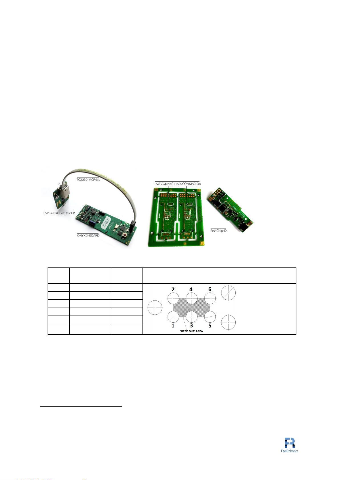
Tag-Connect PCB Pads
For manual programming, the Feel Robotics ESP32 programmer is used which is only
compatible with the TC2030-MCP-NL cable. The programmer features an FT232RL USB
3
to UART.
Figure 1 - ESP32 Programmer
Pad
#
Net Name
Test
PAD
Layout
4
1
GND
TP2
2
EN
TP7
3
2V8
TP1
4
ESP_RX
TP10
5
EPS_TX
TP11
6
IO0/PwrOn
TP8
Table 1 – Tag Connect Pinout
ESP_RX and EPS_TX are used for serial communication from the FT232RL to the ESP32.
EN and IO0 are used to toggle the ESP32 during boot go into bootloader modus so the
FT232RL can upload to code to the flash memory. For programming either the ESP32
Flash-Tool or the python script from Espressif. 2V8 and GND are used to power up the
ESP32 during programming.
1
http://www.tag-connect.com/TC2030-IDC-NL
2
http://www.tag-connect.com/TC2030-MCP-NL
3
https://nl.mouser.com/datasheet/2/163/DS_FT232R-11534.pdf
4
http://www.tag-connect.com/Materials/TC2030-IDC-NL.pdf
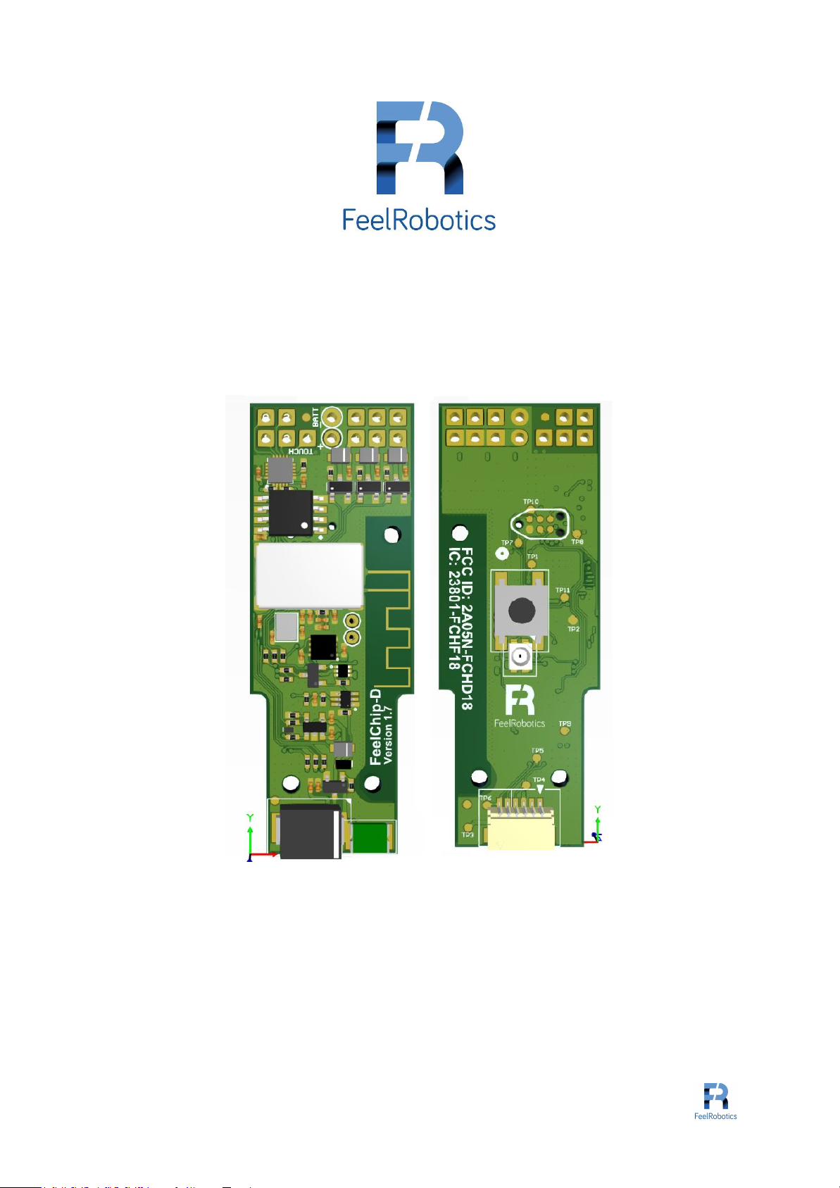
Page 5

Board Overview TOP
Page 6

TOP Parts
PART
UNIT
PART NUMBER
FUNCTION
DESCRIPTION
PART
U1
ESP32-D0WDQ6
MCU
Main processor
PART
U2
WS25Q32JVSSIQ
FLASH
Flash memory
PART
U3
AP7361
LDO
Voltage regulator
PART
U4
Removed
Removed
PART
U5
MPC7382
Lipo Charger
PART
U6
MPR121QR2
TOUCH
Touch sensor
Table 2 - Main units
PART
UNIT
PART NUMBER
FUNCTION
DESCRIPTION
PART
RT1
MSMF050
PTC Reset Fuse
PART
Y1
CLOCK
CLOCK
Table 3 - Miscellaneous
PART
UNIT
PART NUMBER
FUNCTION
DESCRIPTION
PART
Q1
BSS806N
N-Channel Mosfet
Drives Motor 1
PART
Q2
BSS806N
N-Channel Mosfet
Drives Motor 2
PART
Q3
BSS806N
N-Channel Mosfet
Drives Motor 3
PART
Q4
NX3008NBKS
(Dual)
N-Channel Mosfet
On/Off Control
PART
Q5
BSS84LT1G
P-Channel Mosfet
Voltage divider
PART
Q6
DMP2104V
P-Channel Mosfet
Powers LDO
PART
Q7
FDN335N
N-Channel Mosfet
ESD Protector
Table 4 - Switches
PART
UNIT
PART NUMBER
FUNCTION
DESCRIPTION
PART
D1
SMCJ5.0CA-TR
ESD Suppressor
ESD Suppressor
PART
D2
BZX88-B2V7
Zener diode
PART
D3
NSR1020MW
Flyback diode
MTR1
For Motor 1
PART
D4
NSR1020MW
Flyback diode
MTR3
For Motor 3
PART
D5
NSR1020MW
Flyback diode
MTR2
For Motor 2
PART
D6
BAT54WS
Skotty Diode
PART
D7
CD0603-B00340
Skotty Diode
Table 5 - Diodes
Page 7

TOP Pads
PAD
PAD
PART NUMBER
NET
DESCRIPTION
PAD
J1(1)
Touch PAD 1
Touch 4
MPR121 Electrode 6
PAD
J1(2)
Touch PAD 2
Touch 5
MPR121 Electrode 7
PAD
J1(3)
Touch PAD 3
Touch 2
MPR121 Electrode 4
PAD
J1(4)
Touch PAD 4
Touch 3
MPR121 Electrode 5
PAD
J1(5)
Touch PAD 5
Touch 1
MPR121 Electrode 3
Table 6 - Touch Pads
PAD
PAD
PART NUMBER
NET
DESCRIPTION
PAD
J2(1)
Motor PAD 1
VBATT
PAD
J2(2)
Motor PAD 2
MTR 1
For Motor 1
PAD
J2(3)
Motor PAD 3
VBATT
PAD
J2(4)
Motor PAD 4
MTR 2
For Motor 2
PAD
J2(5)
Motor PAD 5
VBATT
PAD
J2(6)
Motor PAD 6
MTR 3
For Motor 3
Table 7 - Motor Pads
TPAD
PAD
PART NUMBER
NET
DESCRIPTION
PAD
W1
Button PAD 1
Short button
PAD
W2
Button PAD 1
Short button
Table 8 - Switch Pads
PAD
PAD
PART NUMBER
NET
DESCRIPTION
PAD
+
Battery PAD
VBATT
PAD
-
Battery PAD
GND
Table 9 - Battery Pads
Page 8

Board overview BOTTOM
Page 9

BOTTOM Parts
PART
UNIT
PART NUMBER
FUNCTION
DESCRIPTION
PART
S1
B3FS-1010
Tactile Switch
Tactile Switch
PART
DS1
AAA3528LSEEZGK
QBKS
RGB LED
RGB LED
PART
J4
SM02B-SRSS-TB
Shrouded Header
USB 5V
Table 10 - Switches
BOTTOM Pads
Testpoint
Net Name
Function
Function
TP1
2V8
LDO Voltage source
2.8V
Programming, Power
Test
TP2
GND
Ground
Programming
TP3
5Vin
USB Voltage source
5.0V
Power Test
TP4
RED 2
Rgb led red
RGB2 Test
TP5
BLUE 2
Rgb led blue
RGB2 Test
TP6
GREEN 2
Rgb led green
RGB2 Test
TP7
EN
ESP32 Enable
Programming
TP8
IO0/PwrOn
ESP32 IO0
Programming
TP9
2V8
LDO Voltage source
2.8V
Programming, Power
Test
TP10
ESP_RX
ESP32 RX programming
Programming
TP11
ESP_TX
ESP32 TX programming
Programming
Table 11 – Pinout
PAD
PAD
PART NUMBER
NET
DESCRIPTION
PAD
J1(1)
TouchPAD1
Touch 4
MPR121 Electrode 6
PAD
J1(2)
TouchPAD 2
Touch 5
MPR121 Electrode 7
PAD
J1(3)
TouchPAD 3
Touch 2
MPR121 Electrode 4
PAD
J1(4)
TouchPAD 4
Touch 3
MPR121 Electrode 5
PAD
J1(5)
TouchPAD 5
Touch 1
MPR121 Electrode 3
Table 12 - TTouchPads
PAD
PAD
PART NUMBER
NET
DESCRIPTION
PAD
J2(1)
Motor PAD 1
VBATT
PAD
J2(2)
Motor PAD 2
MTR 1
For Motor 1
PAD
J2(3)
Motor PAD 3
VBATT
PAD
J2(4)
Motor PAD 4
MTR 2
For Motor 2
PAD
J2(5)
Motor PAD 5
VBATT
PAD
J2(6)
Motor PAD 6
MTR 3
For Motor 3
Table 13 - Motor Pads
Alternative to Tag-Connect PCB Pads the test pads can be used for programming and basic
power testing as described in 5.
Page 10

USB Battery Charger
To test if the battery charger is working 5V is applied over TP3(5V) and TP2(GND). If pads
5
+(VBATT) and –(GND) will have approx. 4.2V across the battery charger is functioning
properly.
LDO Power
To test if the battery charger is working 5V is applied over with POGO pins connected to
6
TP3(5V) and TP2(GND). If POGO pins connected to TP(1) or TP9(2V8) will have 2.8V
across it to TP2(GND) the LDO is functioning properly.
Battery power
To test if the battery power is functioning 4,2V is applied over pads +(VBATT) and –(GND). If
TP(1) or TP9(2V8) will have 2.8V across it to TP2(GND) battery power is functioning
properly.
DC motor
Up to three small brushed DC motors can be controlled by the FeelChip D board. The motors
are driven by three N-channel MOSFETs with designators Q1, Q2, Q3 (MPN: BSS806N) with
a maximum voltage of 3.3V and a maximum current of 3A. PWM can be applied to each of
these channels.
5
Designator in schematic = U5 and part number is MPC7382
6
Designator in schematic = U5 and part number is MPC7382
Page 11

FCC information
The OEM integrator is still responsible for testing their end-product for any additional
compliance requirements required with this module installed.
Host manufacturer (OEM) is responsible for ensuring that the host continues to be compliant
with the Part 15 subpart B unintentional radiator requirements after the module is installed
and operational.
The grantee's FCC ID can be used only when all FCC compliance requirements are met.
End Product Labeling
This transmitter module is authorized only for use in a portable configuration where the
antenna may be installed such that 0 cm may be maintained between the antenna and users.
The final end product must be labeled in a visible area with the following: “Contains FCC ID:
2AO5N -FCHD18”.
Manual Information To the End User
The OEM integrator has to be aware not to provide information to the end user regarding
how to install or remove this RF module in the user’s manual of the end product which
integrates this module.
The end user manual shall include all required regulatory information/warning as shown in
this manual.
 Loading...