

Page 1

Installation, Operation and Maintenance Manual
Steambath Generator Systems
Residential
____________________
IMPORTANT:
Leave this material with the homeowner.
____________________
mr.steam
Models: MX4E-6E
®
Feel Good Inc.
®
Page 2

RESIDENTIAL STEAMBATH GENERATOR SYSTEMS
U S A
Designed, Engineered
and Assembled in the
MODEL ____________________________
Installation, Operation and Maintenance Manual
MODELS: MX4E, MX5E, MX6E
INSTALLER'S SECTION:
IMPORTANT SAFETY INFORMATION . . . . . . . . . . . . . .2-3
PRE-INSTALLATION INFORMATION
Steam Room Guidelines
Water Quality
STEAM GENERATOR
Locating the Steam Generator
Sizing
Clearance Specifications
Generator Dimensions
Replacement Parts
PLUMBING
General Plumbing
Steam Supply Plumbing
Steamheads
ELECTRICAL
Instructions and Electrical Chart
Wiring Diagrams
Connecting Multiple Generators
POST-INSTALLATION INFORMATION
Generator and Start-Up Checkout
Troubleshooting
OPTIONS & ACCESSORIES
Controls
SERIAL NO. __________________________
. . . . . . . . . . . . . . . . . . . . . . . .4
. . . . . . . . . . . . . . . . . . . . . . . . . . . . . . . .4
. . . . . . . . . . . . . . . . . . . .5
. . . . . . . . . . . . . . . . . . . . . . . . . . . . . . . . . . . . .6
. . . . . . . . . . . . . . . . . . . . . . . .7
. . . . . . . . . . . . . . . . . . . . . . . . .8
. . . . . . . . . . . . . . . . . . . . . . . . . . . .9
. . . . . . . . . . . . . . . . . . . . . . . . . . . .10
. . . . . . . . . . . . . . . . . . . . . . .11
. . . . . . . . . . . . . . . . . . . . . . . . . . . . . . . .12
. . . . . . . . . . . . . . . . . .13
. . . . . . . . . . . . . . . . . . . . . . . . . . . .14
. . . . . . . . . . . . . . . . .15
. . . . . . . . . . . . . . . .15
. . . . . . . . . . . . . . . . . . . . . . . . . .16-17
. . . . . . . . . . . . . . . . . . . . . . . . . . . . . . . . . . .18
®
mr.steam
43-20 34th Street, Long Island City, NY 11101
9410 S. La Cienega Blvd. Inglewood CA 90301
Sussman-Automatic Corporation®[email protected] www.mrsteam.com
TEL
: 1 800 76 STEAM
TEL
: 1 800 72 STEAM
AutoFlush . . . . . . . . . . . . . . . . . . . . . . . . . . . . . . 19-20
Condensation Pan
Other Accessories/Options . . . . . . . . . . . . . . . . . . .21
. . . . . . . . . . . . . . . . . . . . . . . . . . .20
HOMEOWNER'S SECTION:
Important
Care Tips
Essential Oils . . . . . . . . . . . . . . . . . . . . . . . . . . . . . .24
Warranty . . . . . . . . . . . . . . . . . . . . . . . . . . . . . . . . .24
Safety Information . . . . . . . . . . . . . . . . . . .22-23
. . . . . . . . . . . . . . . . . . . . . . . . . . . . . . . . . .24
PUR 100420A Rev 1.21
Page 3
mr.steam
®
Installation, Operation & Maintenance Manual
__________________________________________________________________________
I N S T A L L E R S E C T I O N
IMPORTANT SAFETY INFORMATION
As you follow these instructions, you will notice warning and
caution symbols. This blocked information is important for
the safe and efficient installation and operation of this steam
bath systems. These are types of potential hazards that may
occur during installation and operation:
Indicates a potentially hazardous situation,
which, if not avoided, could result in death or serious injury.
Applies to 1-13
1. Never use damaged equipment, doing so may result in an
inoperative or hazardous installation.
2. Discontinue use of the steam generator and control if the
steam generator or control are damaged or otherwise not
functioning properly. Using damaged equipment may
result in an inoperative or hazardous installation.
3. The MAX series of steam generators are for residential use
only. Commercial or other nonresidential applications
void the warranty and may adversely affect product performance and may represent a safety hazard.
4. Read these instructions before installation, operation or
service.
5. Although the MAX steambath generators have been fully
qualified for shipment by MrSteam
be reviewed for proper, safe and enjoyable steam
bathing:
- Verify that the model and accessories specifications are
correct for the incoming line voltage.
- Insure steambath generator has been correctly sized for
the steam room. Pay particular attention to room volume
and construction. If any questions, please refer to
MrSteam sizing and selection guide on page 6 or call
MrSteam.
6. Supervise children at all times.
7. Steam is hot and can cause injury or death if improperly
used. Steam rooms contain steam and elevated temperatures. Please read and observe all warnings in this manual
before installing or using a steam room.
8. Prolonged use of the steam system can raise excessively
the internal human body temperature and impair the
body’s ability to regulate its internal temperature (hyperthermia). Limit your use of steam to 10-15 minutes until
you are certain of your body’s reaction.
9. Excessive temperatures have a high potential for causing
fetal damage during the early months of pregnancy.
Pregnancy or possibly pregnant women should consult a
physician before using a steam bath.
®
, the following must
Indicates a potentially hazardous situation, which, if
not avoided may result in minor or moderate injury or product damage.
This highlights information that is especially relevant
to a problem-free installation.
All information in these instructions is based on the latest product
information available at the time of publication. Sussman-Automatic
Corporation reserves the right to make changes at any time without
notice. More current instructions may be available at
10. Obese persons and persons with a history of heart disease, low or high blood pressure, circulatory system
problems, or diabetes should consult a physician before
using a steambath.
11. Persons using medication should consult a physician
before using a steambath since some medication may
induce drowsiness while other medications may affect
heart rate, blood pressure and circulation.
12. Electric shock hazard. MrSteam steam generators are
connected to high voltage and contain live electrical
components. All installation and service to be performed by qualified and licensed electricians and
plumbers only. Installation or service by unqualified persons or failure to use MrSteam parts may result in property damage or in a personal injury.
13. If you are pregnant, have a coronary condition, are in
poor health, are being treated for any other medical
condition, or are using medication or drugs, MrSteam
recommends that you obtain the approval of a physician before use.
Applies to 14-17
14. The wet surfaces of steam enclosures may be slippery.
Use care when entering or leaving. To prevent slip and
fall hazards non-skip strips must be installed on the
steam room floor.
15. The steamhead is hot. Do not touch the steamhead
and avoid the steam near the steamhead.
16. The information in this manual should be used in conjunction with consultations with an architect, designer
and contractor in determining factors necessary in providing a suitable and safe steam room.
17. MrSteam steam generators must be operated with
MrSteam controls and accessories only, and are to be
installed strictly in accordance with the specific instructions contained in this manual and as supplied in the
manuals provided with the controls or accessories.
www.mrsteam.com.
2
Page 4
mr.steam
®
Installation, Operation & Maintenance Manual
__________________________________________________________________________
IMPORTANT SAFETY INFORMATION (cont.)
Applies to 18-23
18. This document contains important safety, operation
and maintenance information. Leave this document
with the homeowner. Do not discard this document.
19. Consider any controls and accessories before installation. Read the Installation and Operation Manual
of all controls and accessories available at
www.mrsteam.com.
20. Record the model and serial number of the steam
generator in the space provided in the table of
contents of this manual.
21. If acrylic, fiberglass or other non-heat resistant materials
are used as part of the steam room enclosure, consult
with the material manufacture and see page 12,
“Steamhead Installation" for additional details.
22. Carefully inspect the steam generator and packaging for
shipping damage. In the event of shipping damage,
please contact the carrier for claim information.
MrSteam customer service department can assist you
with any missing or damaged parts.
23. The physical size of the steam generator, clearance for
plumbing servicing, and its distance from the steam
room must all be considered before installation.
I N S T A L L E R
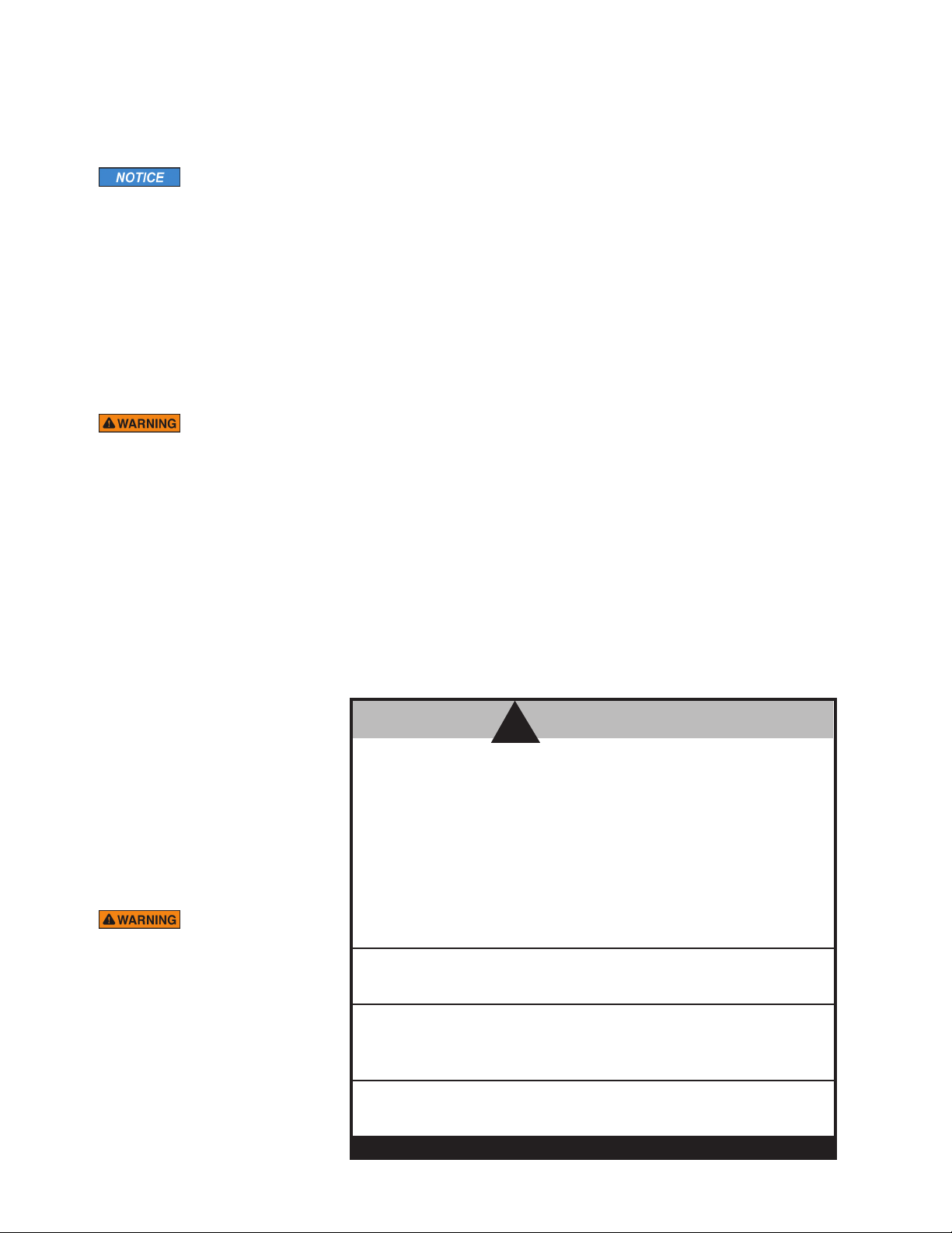
HYPERTHERMIA
degrees above the normal body temperature of 98.6° F. The symptoms of hyperthermia include
an increase in the internal temperature of the body, dizziness, lethargy, drowsiness, and fainting.
The effects of hyperthermia include:
a) Failure to perceive heat.
b) Failure to recognize the need to exit the steambath.
c) Unawareness of impending risk.
d) Fetal damage in pregnant women.
e) Physical inability to exit the steambath.
f) Unconsciousness.
The use of alcohol, drugs, or medication can greatly increase the risk of hyperthermia.
occurs when the internal temperature of the body reaches a level several
WARNING
!
REDUCE THE RISK OF OVERHEATING AND SCALDING
1.
EXIT IMMEDIATELY IF UNCOMFORTABLE, DIZZY OR SLEEPY.
STAYING TOO LONG IN A HEATED AREA IS CAPABLE OF CAUSING OVERHEATING.
2. SUPERVISE CHILDREN AT ALL TIMES.
3. CHECK WITH A DOCTOR BEFORE USE IF PREGNANT, DIABETIC, IN POOR HEALTH
OR UNDER MEDICAL CARE.
4. BREATHING HEATED AIR IN CONJUNCTION WITH CONSUMPTION OF ALCOHOL,
DRUGS, OR MEDICATION IS CAPABLE OF CAUSING UNCONSCIOUSNESS.
The manual supplied with
the generator includes a peel and stick
warning label. Its proper use is an essential
part of providing a safe environment for
steam room users. The peel and stick
warning label must be applied to the wall
of the shower or steam enclosure, at a
point that is visible to all users. Failure to
install this sticker may result in serious
injury or death. The location where this
owner's manual is kept shall be written in
the space provided on the label using
permanent ink. For a replacement warning
label contact MrSteam customer service at
1-800-76-STEAM or [email protected].
5. DO NOT CONTACT STEAMHEAD OR STEAM AT THE STEAMHEAD.
REDUCE THE RISK OF SLIPPING AND FALL INJURY
1. USE CARE WHEN ENTERING OR EXITING THE STEAM ROOM. FLOOR MAY BE SLIPPERY
NOTE: FOR ADDITIONAL SAFETY CONSIDERATIONS SEE OWNER’S MANUAL
WHICH IS KEPT:_______________________________________
THE OWNER’S MANUAL CAN BE FOUND AT WWW.MRSTEAM.COM
USE OF STEAM ROOM IN CONJUNCTION WITH CONSUMPTION OF ALCOHOL CAN BE
DANGEROUS AND CAN RESULT IN INJURY THROUGH SLIP AND FALL OR OTHERWISE.
mr.steam
®
43-20 34th Street , Long Island City NY 11101 1 800 76 STEAM www.mrsteam.com PUR100378 8.18
3
Page 5

mr.steam
®
Installation, Operation & Maintenance Manuals
______________________________________________________________________________
PRE-INSTALLATION CONSIDERATIONS
STEAM ROOM GUIDELINES
To prevent slip and fall hazards, non-slip flooring
or non-slip floor strips must be installed in the steam room.
Applies to 1-9
1. The steam room must be completely enclosed, with full walls,
I N S T A L L E R
door, floor and ceiling as required to contain the steam and
prevent moisture damage outside the steam room.
2. It is recommended that a gasketed door is used for steam
containment.
3. Check the suitability of any materials with the
manufacturer. All steam room surfaces and products must be
constructed of heat-resistant and water-resistant, non-corrosive surface, such as tile, marble, molded acrylic, or other
non-porous material.
4. Provide a floor drain for condensate gravity drainage.
5. No heating, venting or air conditioning devices
should be installed inside the steam room.
WATER QUALITY
Applies to 1-5
1. The water supply should be tested prior to installation. If
the mineral content exceeds the following recommended
limits, water treatment is recommended.
RECOMMENDED FEEDWATER QUALIT Y
Hardness, ppm 8 – 85 (~0.5 – 5 gpg)
P-Alkalinity, ppm 85 – 410 (~5 – 24 gpg)
T. Alkalinity, ppm 200 – 500 (~12 – 30 gpg)
pH (strength of alkalinity) 8.0 – 11.4
6. Steam room tile construction information is available
from the Tile Council of America, Inc. by purchasing
the TCA Handbook for Ceramic Tile Installation.
Tel. (864) 646-8453 or www.tileusa.com.
7. Steam room windows should be double paned and
tempered safety glass.
8. For optimal results, limit steam room ceiling height
to 8 feet. Exceeding 8 feet may require a higherrated steam generator. See page 6 for additional
steam generator sizing information.
9. The information in this manual should be used in
conjunction with consultations with an architect,
designer and contractor in determining factors necessary in providing a suitable and safe steam room.
4. In “hard” water areas, the manual drain valve should
opened as required to fully flush out accumulated
be
materials, salts and other particles which are natural
by-products of boiling water.
5. The optional AutoFlush automatically drains the
generator following each use. A time delay allows the
water to cool down (about two hours) before it drains
by gravity for a safe and gentle operation. See page
19 for additional AutoFlush information.
2. An analysis of the water must be made by a recognized and
reliable water treatment company to ascertain the condition
and treatment required.
3. Poor water quality can affect steam generator efficiency
and/or result in steam generator damage. Water contains
impurities in solution and suspension. These impurities concentrate in the generator. The concentration of these impurities increases as more water is introduced into the generator and steam is produced. A deposit or “scale” will form
on the generator internal surfaces. This deposit can interfere with the proper generator operation and cause generator failure. The concentration of these impurities is generally
controlled by the water quality and by periodic draining of
the generator.
4
Page 6

mr.steam
®
Installation, Operation & Maintenance Manuals
________________________________________________________________________
LOCATING THE STEAM GENERATOR
Applies to 1-6
1. Do not route iSteam, AirTempo, iTempo/Plus, iTempo OR
any control wiring inside conduit together with power lines
or close to hot water or steam piping. Doing so may result
in an inoperative or hazardous installation.
2. Installation or operation of the steam generator in an
ambient temperature above 113˚ F (45 °C) may result in a
hazardous condition or property damage.
3. Do not install the steambath generator inside steam room,
a shock hazard and/or equipment damage will occur.
4. Do not install steambath generator outdoors or
wherever environmental conditions may result in a
shock hazard and/or equipment damage.
5. To prevent a fire hazard, do not install the steambath generator near flammable or corrosive materials or chemicals
such as gasoline, paint thinners, or the like.
6. Installation in areas having high concentrations of chlorine
(such as pool equipment room) must be avoided.
Applies to 7-11
7. Do not install the steambath generator or plumbing line in
an unheated attic or any locations where water could freeze
and cause pipes to rupture and cause property damage.
8. Steam piping, safety valve, drain valve and plumbing
become hot during operation and remain hot after shutdown for a period of time. Provide appropriate protection,
including insulating plumbing lines. Avoid plumbing runs
and steamhead locations that can come in contact with
bathers to prevent a burn hazard.
9. Install the steambath generator on a solid and level surface.
10. Install the steambath generator in an upright position only
to prevent damage to the generator, pipes and electrical
system. Failure to install in an upright position may result
in a leak or shock hazard.
11. Do not hang the MAX steam generator on a wall. Hanging
the MAX generator on a wall may result in a leak, shock
hazard or equipment damage.
Applies to 12-18
12. Provide a minimum of 18"on the left side and 21" at
the top of the steam generator or as required for
servicing. See page 7 for complete information.
13. Select a location as near as practical to the steam
room. Typical locations include heated attic or basement.
14. The standard length of the cable for connecting the
control to the steam generator is 30 feet. The steam
generator and control must be located accordingly.
A 60 foot cable is available as a special order part for
®
iTempo
60). The maximum cable length is 60 feet.
15. Install anti-water hammer device as necessary.
16. The control cable should be run in a dedicated 1-inch
conduit to facilitate installation and service.
17. Provide unions as required to facilitate installation and
removal of the steam generator.
18. The minimum clearance from combustible surfaces is
zero all around.
(PN 103990-60) and for iSteam®(PN 104117-
I N S T A L L E R
5
Page 7
mr.steam
®
Installation, Operation & Maintenance Manuals
______________________________________________________________________________
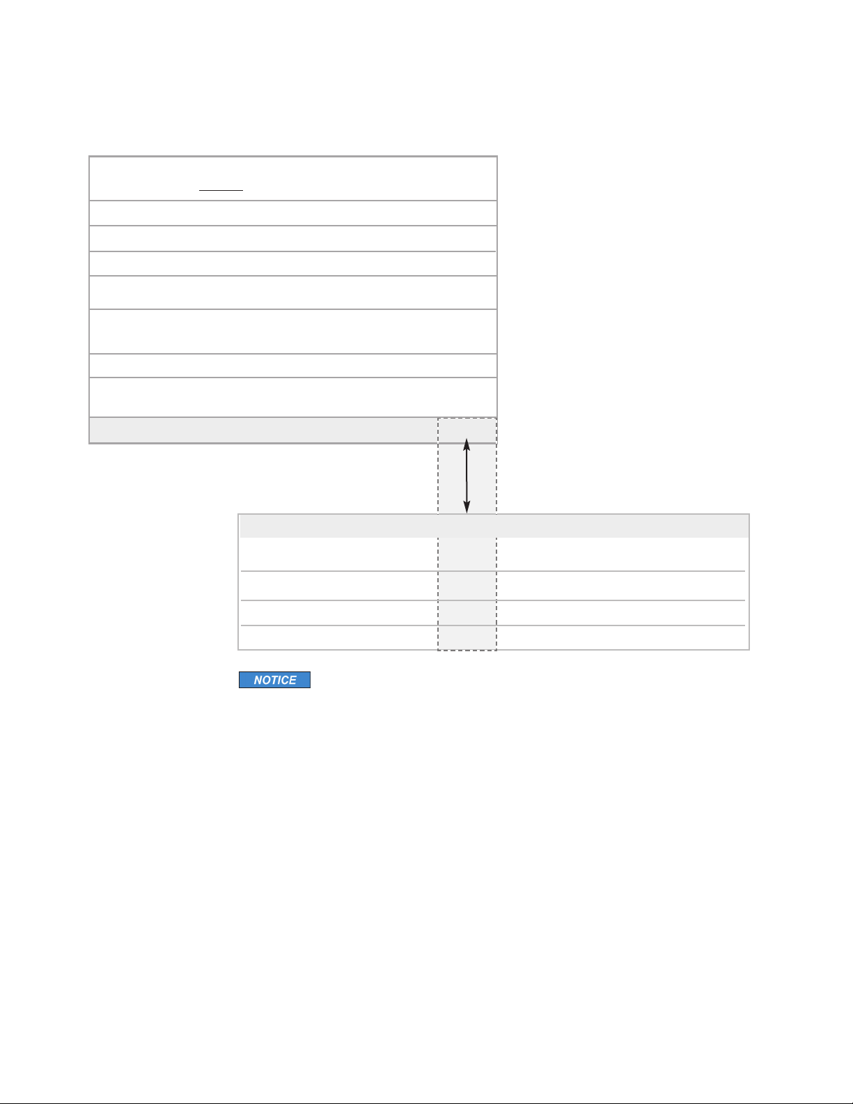
CHECKING STEAM GENERATOR FOR CORRECT SIZING
Materials of construction, room size and special design features such
as large glass areas, all affect
1.
Measure length, width & height in feet of the steam/shower or tub/shower
Multiply the Length ____ x Width_____ x Height _____ =
2.
Construction Materials:
the steam generator model selection.
ROOM VOLUME
I N S T A L L E R
For ceramic or porcelain tile on
cement board or mortar bed
For natural stones: natural marble,
stone, shale, glass block or concrete
For Acrylic or Fiberglass
3.
Ceiling Height: For each foot above 8 feet (max. of 10 feet)
4. Total Adjusted Room Volume
Compare your Room Volume to the Chart below
and select the appropriate model.
R E S I D E N T I A L S T EA M G E N E R AT O R S S P E C I F I C AT I O N C H A R T
Model No. KW 240v/1PH)† Size‡ Room Vol. Gallons†† Dimensions* Wt. (lbs)**
MX4E 20 84 3
MX5E 24 100 1
MX6E 30 125 2/0
Applies to 1-8
1. † Amps are for 240/1PH rated units.
2. ‡Wire size (AWG) based on minimum 90˚C rated THHN copper
conductors. Refer to the National Electrical Code for other types of
conductors.
3. *Dimensions are for generator only, without AutoFlush or plumbing
features. See page 8 for complete dimensional information.
4. **Shipping weight is for generator only, without control or steamhead.
5. †† Water usage based on 20 minutes of operation.
6. For steam rooms constructed of acrylic or synthetic materials, subtract
15% from the room volume.
7. The MrSteam Sizing Chart allows for up to 60 feet of insulated steam
piping from the generator to the steam room. If a 60 foot piping is
exceeded consult with factory.
8. Occasionally a steam room has unforeseeable or hidden construc-tion
that requires special sizing or other consideration. MrSteam is not
responsible if unconventional and/or unforeseeable materials or
construction details result in a unit that does not operate to specification. If the sizing chart does not include the required options, please
contact MrSteam to review sizing.
Add 0%
Add 5 0%
Subtract 40 %
To the Adjusted Room Volume
Amps (for Wire Total Adj. Water Usage Shipping
Add 15%
483-6 78
679-822
823-964
2.7 25
3.2 25
4.0 25
1
⁄8"L x 203⁄4"H x 7
1
⁄8"L x 203⁄4"H x 7
1
⁄8"L x 203⁄4"H x 7
7
⁄8"D 67
7
⁄8"D 67
7
⁄8"D 67
6
Page 8
mr.steam
24
”
Min.
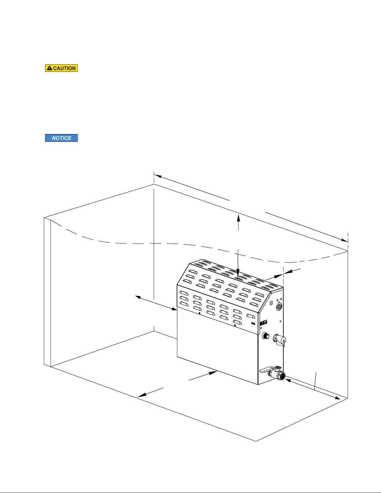
Service Area Clearance
18
”
Min.
Service Area Clearance
21
”
Min. Ceiling Height
Clearance Area
58
”
Min.
Clearance Area
0”Min.
Provide a minimum of
12 inches of clearance
as required for steam
piping, drain,
AutoFlush, water feed
and pressure
relief plumbing
®
Installation, Operation & Maintenance Manual
__________________________________________________________________________
STEAM GENERATOR CLEARANCE SPECIFICATIONS
Applies to 1-2
1. Do not install MAX series inside a vanity or other small enclosed spaces. Do
not install under the steam room bench. Installing the MAX steam generator in
a small enclosed space may result in elevated temperatures and an inoperable
steam generator.
2. Locate the MAX series generator in a room with ventilation as required to prevent an increase in ambient temperature. Failure to provide adequate ventilation may result in elevated temperature and an inoperable steam generator.
Applies to 3-4
3. Minimum Clearance from Combustible Surfaces is zero all around.
4. For ease of servicing and installation, MrSteam recommends a minimum
clearance around the steam generator as shown.
I N S T A L L E R
All drawings are for illustrative purposes only
7
Page 9
mr.steam
I
H
F
G
E
%
C
J
A
D
K
Side View Showing
Element Access Panel
18”
for servicing
L
M
®
Installation, Operation & Maintenance Manuals
______________________________________________________________________________
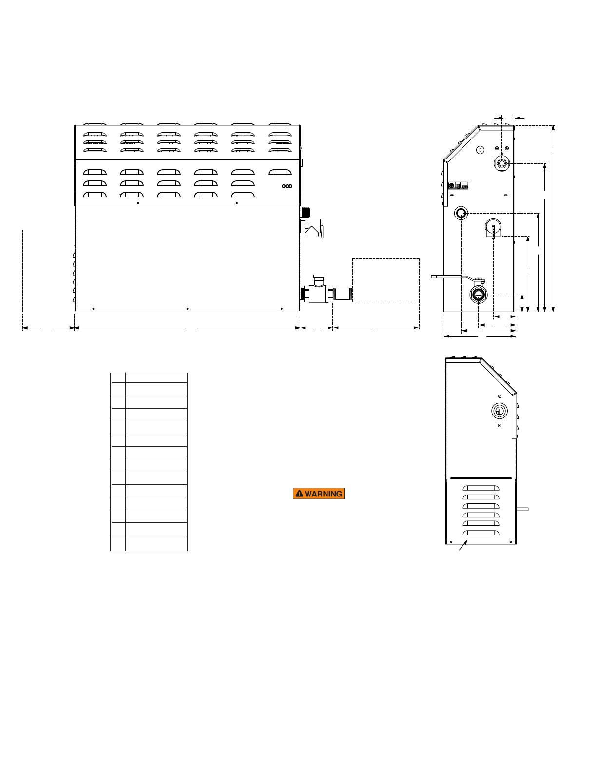
STEAM GENERATOR DIMENSIONS
I N S T A L L E R
Dimensions
MX4E-6E
3
9
⁄4 (248)
A
11 (280)
B
C
D
E
G
H
K
M
NOTES
1. M=Optional AutoFlush.
2. All units in inches (MM)
1
16
⁄2 (419)
3
20
⁄4 (527)
3
1
⁄8 (34)
3
2
⁄8 (60)
F
7
5
⁄8 (150)
7
5
⁄8 (150)
7
7
⁄8 (200)
I
7
1
⁄8 (48)
J
1
25
⁄8 (638)
3
2
⁄8 (60)
L
6
Dimension includes 3
nipple
3
⁄8 (162)
:
(not supplied
1
)
⁄2
inch
TO AVOID
EQUIPMENT DAMAGE DO NOT
CONNECT POWER SUPPLY
DIRECTLY TO ELEMENTS.
Connecting power directly to the
elements will result in a dry fire
and result in elevated temperatures and a fire hazard.
All drawings are for illustrative purposes only
8
Page 10
mr.steam
Transformer
Fuses
Transformer
Nipple
(not included)
Circuit Board
Water Feed
Solenoid
Water
Inlet
Safety Valve
AutoFlush
Valve
(optional)
Stainless Steel Tank
Heating Element
Express Steam
Heater (optional)
Element
Access
Cover
Liquid
Level
Probe
Plug and Play
Connection
Contactors
Power
Supply
Knock-Out
Power
Block
Steam Outlet
Manual
Drain Valve
®
Installation, Operation & Maintenance Manual
_________________________________________________________________________
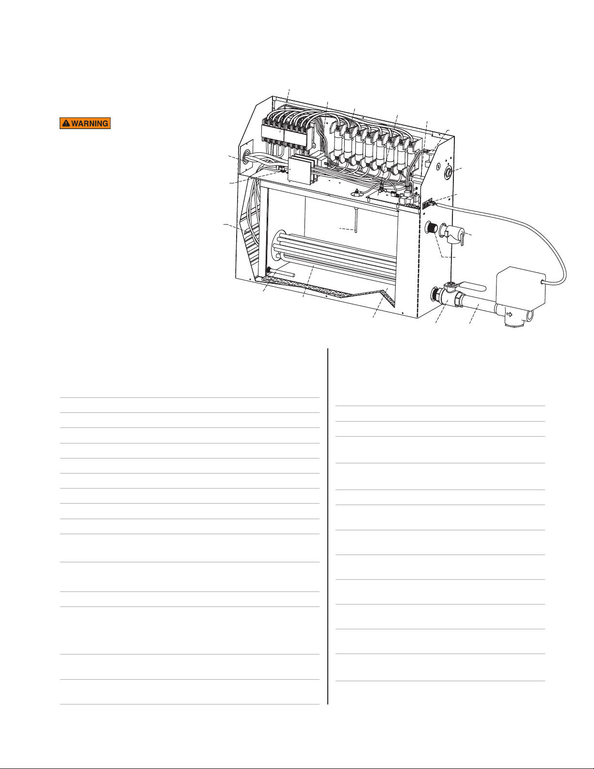
PARTS IDENTIFICATION DIAGRAM
(shown with AutoFlush®with cover removed)
ALL DRAWINGS FOR
ILLUSTRATIVE
PURPOSES ONLY.
Some components may be
omitted or altered for
clarity. Do not use for
wiring, plumbing, repair
or other purposes not
related to component
identification.
I N S T A L L E R
REPLACEMENT PARTS LIST
__________________________________________________________________________________________
Part No. Description Generator
__________________________________________________________________________________________
103036 Manual Drain Valve All Models
Part No. Description Generator
___________________________________________________________________________
103453 Contactor 50A 4-pole All 1-Phase
99297 Safety Valve 15PSI All Models
100479 Water Feed Solenoid Valve w/filter All Models
100477-3 Transformer 24VAC All Models
104288 Circuit Board All Models
103904 Tandem Cable for 2 generators (12 ft.) All Models
104423 Liquid Level Probe All Models
99096MX Heating Element Gasket All Models
103938RD Acrylic Shield for Round All Models
103938SQ Acrylic Shield for
103917 Tandem Cable for up to 5 generators (30 ft.) All Models
103990-60 Cable for iTempo & AirTempo Control (60 ft.) All Models
104117-30 Cable for iSteam, AirTempo & iTempo (30 ft.) All Models
104117-60 Cable for iSteam (60 ft) All Models
MSTS-30
MSTS-60
Remote Temperature Probe
(integral 30ft cable)
Remote Temperature Probe
All Models
All Models
(integral 60ft cable)
103660 Fuse block 2-pole All Models
104415 Power Block 175A All 1-Phase
Models
(except MX6E
99314 Power Fuse 60A 250V All Models
29201BMS
29201CMS
29241BMS
29241CMS
29301BMS
29301CMS
208V)
104419 Power Block 270A MX6E-Phase
104015 Express Steam Thermostat All Express
208V
Models
104019 Heating Element for All Express
Steamhead
Square All Models
Steamhead
Heating Element 20 KW 208V
Single Phase
Heating Element 20 KW 240V
Single Phase
Heating Element 24 KW 208V
Single Phase
Heating Element 24 KW 240V
Single Phase
Heating Element 30 KW 208V
Single Phase
Heating Element 30 KW 240V
Single Phase
Express Steam
Models
MX4E
MX4E
MX5E
MX5E
MX6E
MX6E
Models
For other voltages and phases contact MrSteam
9
Page 11

mr.steam
®
Installation, Operation & Maintenance Manuals
______________________________________________________________________________
PLUMBING
GENERAL
1. All plumbing shall be performed by a qualified licensed
plumber and in accordance with applicable National
and local codes.
Applies to 2-4
2. Use unions on all pipe connections as required for serv-
I N S T A L L E R
ice and removal of the steam generator.
3. Use only brass piping or rigid copper tubing. Use only
piping as permitted by codes.
4. Do not use black, galvanized, PVC pipe or PEX except
as noted below.
Water supply and steam piping must be
flushed to remove flux and other debris prior to
connecting the steam generator. Failure to flush the
steam piping may result in flux poisoning or a hazardous
condition. Failure to flush the steam piping may result in
blockage or an inoperable system.
WATER SUPPLY (3⁄8" NPT)
Applies to 1-9
1. Install a shut off valve in the water supply line.
2. It is recommended to install a strainer in the water
supply line.
3. Install an anti-water hammer device as required.
4. Install an approved backflow preventer as required by
local codes.
5. Connect the generator to a cold water line.
6. Water feed line may be flexible copper tubing, braided
hose, PVC or PEX if permissible by local codes.
7. Do not overheat inlet solenoid valve with solder con-
nections. Overheating will damage parts and result in
a water leak.
8. Flush inlet water line thoroughly before making
connection to the generator.
9. To reduce operating noise, reduce feed water pressure
to between 15 - 20 psi is recommended. Optional
pressure reducing valve part number 104198.
DRAIN (1" NPT)
Applies to 1-3
1. Do not connect the generator drain line to an
undersink trap.
2. Do not drain into a steam enclosure or any location where
accidental contact with drain water may occur. In the event
of a power failure the AutoFlush valve will open and may
discharge boiling water causing a scalding hazard.
3. Do not connect the drain valve to the steam piping.
Connecting the drain line to the steam piping may allow
boiling water to discharge through the steamhead causing
a scalding hazard.
Applies to 4-8
4. A drain valve is provided to facilitate maintenance and
servicing. Provide a drain line connection from steambath
generator drain valve according to National and Local Codes.
5. Check local plumbing code for receptor, trap and vent
requirements.
6. Do not connect Drain line and Safety Valve line together.
7. The steam generator drains by gravity. Plumb all drain lines
accordingly.
8. See page 20 for installation of the optional Condensation
Pan.
SAFETY VALVE (3⁄4" NPT)
Where permitted by local codes, provide an outlet plumbing
connection for safety valve.
Applies to 1-3
1. To insure proper and automatic safety valve operation do not
connect a shut off valve or a plug at safety valve outlet.
2. Do not connect a shut off valve or any obstruction
to the safety valve.
3. Do not connect the safety-valve output to the steam piping.
Plumbing Specifications
MX4E-6E
Water Inlet
Steam Outlet
Safety Valve
Manual Drain Valve 1" NPT
AutoFlush Valve 1" NPT
3
” NPT
⁄
8
3
” NPT
⁄
4
3
” NPT
⁄
4
AROMASTEAM
If the optional AromaSteam Fragrance Delivery
System (
ing fitting must be installed at a designated location on the
steam piping. See the MrSteam AromaSteam Operation and
Instruction Manual (
before the steam piping is installed at the technical downloads
section of www.mrsteam.com.
10
PN:MS AROMA
) is to be installed, a 90 degree T plumb-
PN
: 100402) for installation information
Page 12
mr.steam
STEAM R OOM
STEAM
GENERATOR
SteamHeads
Union
1/2”
Steam
Supply
Fitting
Tee
Fitting
3/4” Steam
Piping
6-12”
Above Floor
Min. 16”
Steam
Generator
Steam
Generator
Steam
Generator
Steam
Generator
Steam
Generator
Steam
Piping
Steam
Head
Steam
Piping
Steam
Head
Steam
Piping
Steam
Head
Steam
Piping
Steam
Head
Steam
Piping
Steam
Head
Steam
Generator
Steam
Piping
Steam
Head
®
Installation, Operation & Maintenance Manuals
________________________________________________________________________
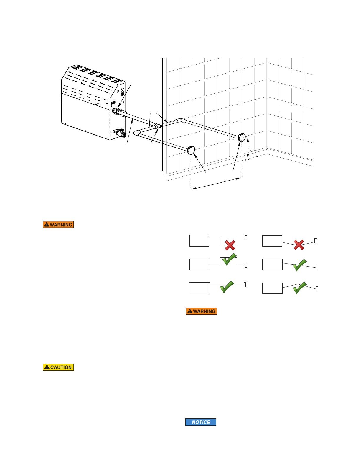
STEAM SUPPLY PLUMBING (
3
⁄4" NPT)
ALL DRAWINGS FOR ILLUSTRATIVE PURPOSES ONLY.
STEAM PIPING (1⁄2" NPT)
I N S T A L L E R
Applies to 1-5
1. Do not install any valve
in steam piping. The flow of
steam must be unobstructed.
2. MAX Steam Generators must be installed with two or
more steamheads. Using less than two steamheads will
result in too much steam coming out of one steamhead
and may result in scalding and personal injury.
3. Never use less than two steamheads.
4. Never use less than 3⁄4” steam piping from generator to
Tee fitting. Using less than 3/4” steam piping will result
in too much steam coming out of the steamheads and
may result in scalding and personal injury.
5. Install steam piping as required (including routing, fit-
tings and length of pipe) to insure an equal amount of
steam reaches each steamhead. Unequal steam piping
will result in too much steam coming out of one steamhead and may result in scalding and personal injury.
Applies to 6-10
6. Use brass pipe or copper tubing from unit to steamhead
as permitted by codes.
7. Insulate steam piping with fiberglass pipe insulation or
similar insulation rated 212° F or higher.
8. Pitch steam piping 1/4" per foot towards steamhead or
steam generator to avoid valleys and trapping of condensate. Running the steam piping down and then up will
create a steam trap blocking or restricting the flow of
steam.
Failure to pitch the steam piping as
required for condensate to drain, may cause condensate to
block the flow of steam. Blocking the steam flow may cause
steam pressure to discharge boiling water through the
steamhead, resulting in a scalding hazard. Blocking the flow
of steam may cause steam to discharge through the safety
valve, resulting in a scalding hazard.
9. Do not install piping so one steamhead has more steam
than the other steamhead. Installing piping so one
steamhead has more steam than the other steamhead
may result in an excessive amount of steam to one
steam, resulting in a scalding or burn hazard.
10. Consult with qualified designer, architect or contractor
for steam room construction details.
For the optimal distribution of steam,
steamheads should be spaced evenly throughout the steam
room.
11
Page 13
mr.steam
®
Installation, Operation & Maintenance Manual
___________________________________________________________________________
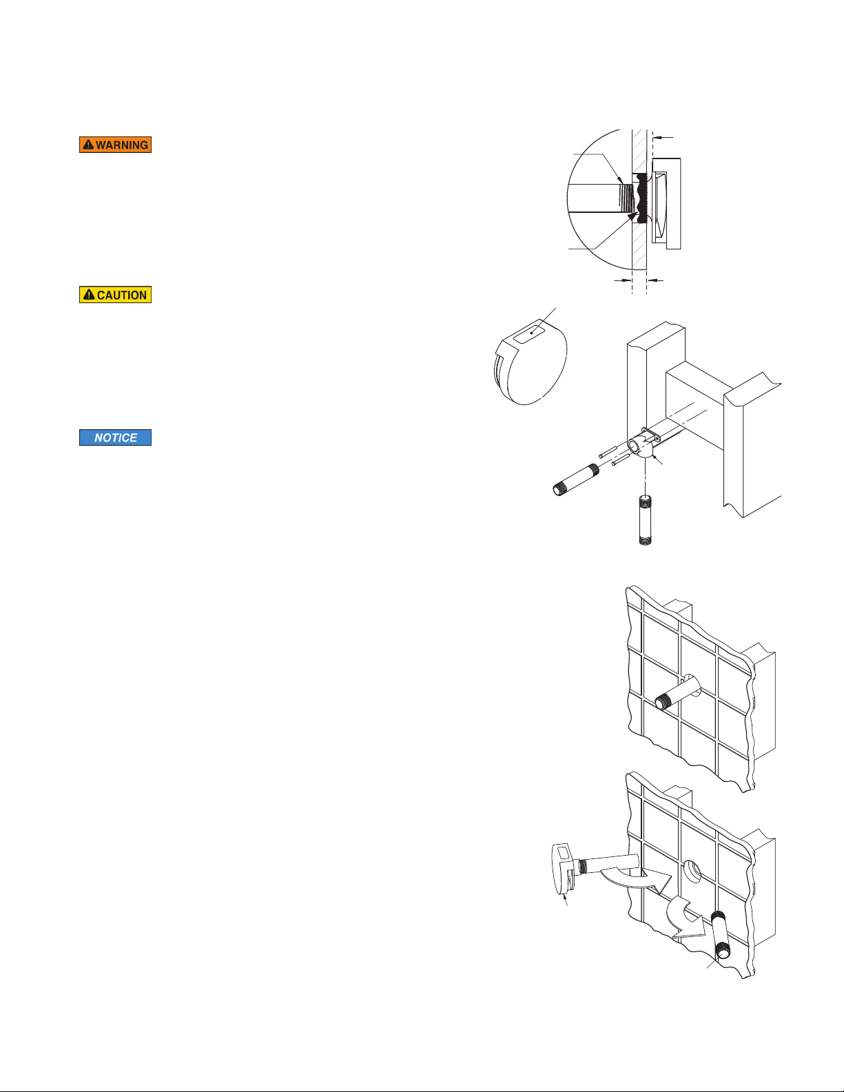
STEAMHEAD INSTALLATION
Applies to 1-2
1. MAX Steam Generators must be installed with two or more
steamheads. Using less than two steamheads will result in too
much steam coming out of one steamhead and may result in
scalding and personal injury.
2. Because the steamhead and direct steam emissions are very hot, locate
the steamheads where incidental contact by bather with the steamheads
or direct steam emission cannot occur.
I N S T A L L E R
3. Do not disassemble steamheads. The steamheads are shipped fully
assembled and requires no additional assembly. Disassembly of the
steamheads may result in a burn hazard.
4. Seal the gap between the wall and the steam supply pipe with silicone
(or other 212˚F heat resistant sealant) as required to create a moisture
seal. Failure to create a moisture seal may allow moisture to enter the
wall cavity and cause property damage.
5. To preserve the steamhead finish, do not use wrench or other tools to tighten. Do
not use abrasive cleansers or chemicals. Use only water with mild soap and a nonabrasive sponge.
6. Contact the supplier of acrylic, fiberglass and other non-heat resistant enclosures
for recommended steamhead location. Use Acrylic Shield PN 103938RD (round)
or PN 103938SQ (square). See instructions provided with steam shield.
Applies to 3-4
Applies to 5-6
Use Teflon®or
equal sealant on
pipe threads
Apply with silicone or equal
sealant as required for
moisture seal.
Oil Well
Steam
Supply Pipe
STEP 3
End of pipe to be recessed
1/4"
1/8" (with Acrylic Shield)
Drop Ear
Fitting
1/8" minimum clearance
required when Acrylic Shield
is used.
See installation
instructions provided with the
Acrylic Shield.
(without Acrylic Shield)
STEP 1
1. Locate the steamheads 6-12 inches above floor.
2. For tub/shower enclosures, install the steamheads 6 inches above tub top edge.
3. To prevent door seals or any material, product or surface from deteriorating,
do not locate the steamheads where direct steam emission would come in
direct contact with non-heat or moisture-resisitant products or materials.
4. To reduce noise, do not locate steamhead within 12" from a wall.
STEP 2
Provide 1
STEP 3
Secure a bronze drop ear fittings to a header and run a 3/4" copper steam piping
from the steam generator to tee fitting and 1/2" steam piping after tee fitting to the
drop ear fittings. Install a temporary nipples (6" or longer) in the drop ear fittings to
locate the steamheads after the wall is finished.
STEP 4
After the wall has been finished, mark the surface of the wall for both nipples.
Remove the nipples and measure the portion that was in the wall (the end to your
mark). Subtract 1⁄4" from that dimension and select a brass nipples of that length to
finish the installation.
STEP 5
Wrap teflon tape around the threads of the new nipples and screw the nipples into the
steamheads. Wrap teflon tape around the threads of the nipples and screw the nipples
and steamhead assemblies into the drop ear fittings in the wall. Hand tightening is
sufficient when teflon or equal pipe thread sealing compound is used. The steamheads
should be flush with the oil well facing up.
1
⁄2
" clearance holes around the steam pipes.
STEP 4
STEP 5
steamhead
Locating Nipple
12
All drawings are for illustrative purposes only
Page 14
mr.steam
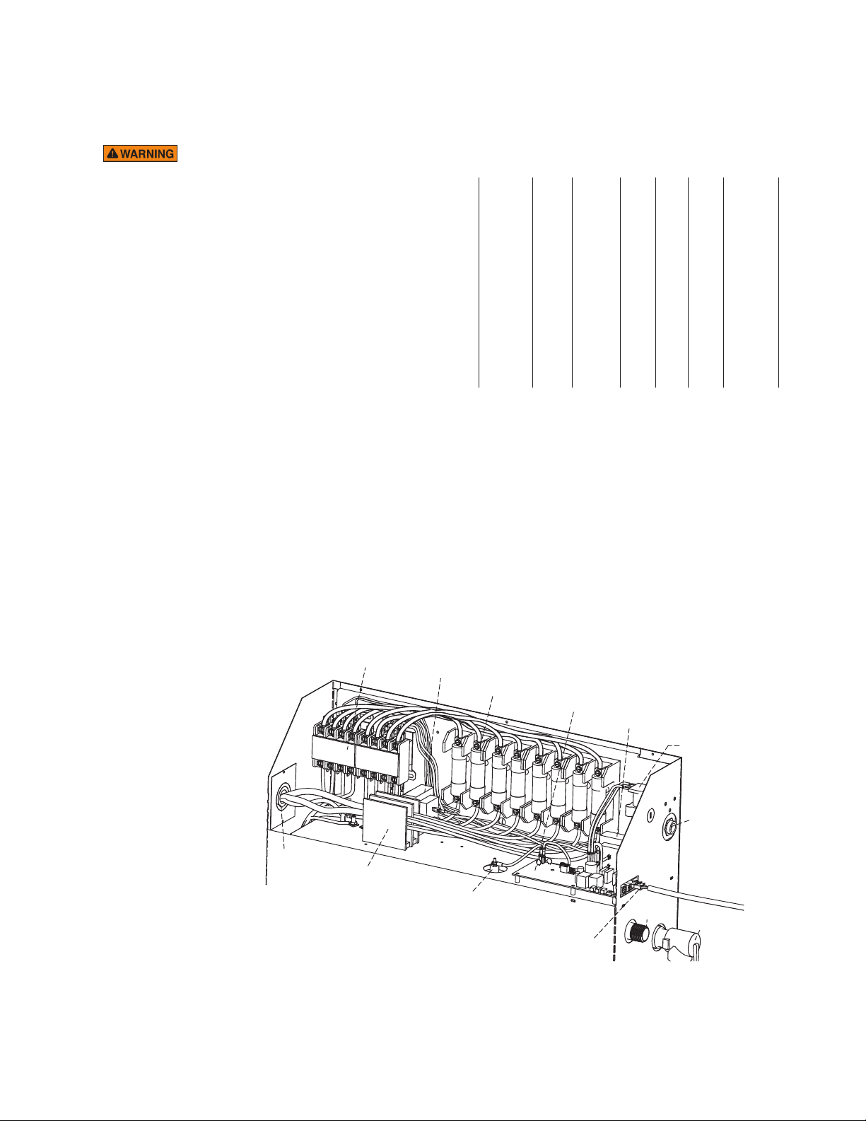
Transformer
Transformer
Circuit Board
Water Feed
Solenoid
Water
Inlet
Liquid
Level Probe
Plug and Play
Connection
Fuses
Contactors
Power Block
Steam
Outlet
Safety
Valve
Power
Supply
Knock-Out
®
Installation, Operation & Maintenance Manuals
________________________________________________________________________
ELECTRICAL
Applies to 1-9
1. Never use damaged equipment, doing so may result in an
inoperative or hazardous installation.
2. All electrical wiring installation to be performed by a qualified
licensed electrician in accordance with National Electrical
Code and Local Electrical Code.
3. Connect electrical power supply to the power block only.
Do not connect power supply directly to elements.
Connecting power directly to the elements may result in a
dry fire and result in elevated temperatures and a fire hazard.
4. For 208V units do not apply more than 218V service.
5. Use minimum 90˚ C/300V rated insulated copper conductors
only, sized in accordance with National Electrical Code and
Local Electrical Code for the current in Ampere Chart. If
allowed by codes, NM cable may require a larger wire size
than as listed on the chart.
6. Connect suitably sized equipment grounding wire to ground
terminal provided. Neutral (white) wire is not required for
208V and 240V units.
7. Provide suitable over-current protection (fuses or circuit breaker).
8. Provide a power supply disconnect within sight of the steam
generator or one that is capable of being locked in the open
position as required by code.
9. Wire size (AWG ) is based on minimum 90˚ C rated THHN
copper conductors. Refer to the National Electric Code for
other types of conductors.
__________________________________________________________________________________
Model No.
___________________________________________________________________________________
MX4E
__________________________________________________________________________________
MX5E
__________________________________________________________________________________
MX6E
__________________________________________________________________________________
* See page 6 for room sizing
†
All specifications shown are for 208V and 240V.
Consult factory for other voltage specifications.
EL EC T R I C A L CH A R T
Vol Max Room Wire Size
(Cu. Ft.*)
678
822
964
Volts†Phase Amps
KW
208 1 97 1
20 3 56 4
240 1 84 3
3 48 6
208 1 116 1/0
24 3 67 4
240 1 100 1
3 58 6
208 1 145 3/0
30 3 84 2
240 1 125 2/0
3 73 3
(AWG) for 25˚ C
I N S T A L L E R
13
All drawings are for illustrative purposes only
Page 15
I N S T A L L E R
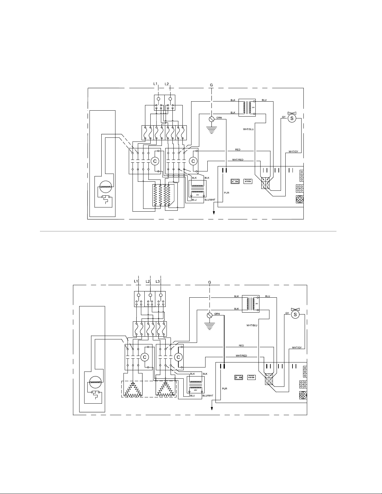
CONTACTOR
EXPRESS
STEAM
(optional)
3/4 PL
Terminal
Block
HEATING ELEMENT
TO PROBE
CIRCUIT BOARD
TRANSFORMER
TRANSFORMER
HEATER
THERMOSTAT
POWER INPUT
GROUND
WATER
FEED
SOLENOID
VALVE
FUSES
AutoFlush
(optional)
HomeWizard
iGenie (optional)
iSteam, AirTempo
iTempo/Plus or
iTempo Control
CONTACTOR
EXPRESS
S
TEAM
(
optional)
2
/4PL
Terminal
Block
H
EATING ELEMENT
T
O PROBE
CIRCUIT BOARD
AutoFlush
HomeWizard
iGenie (optional)
iSteam, AirTempo
iTempo/Plus or
iTempo Control
TRANSFORMER
TRANSFORMER
HEATER
THERMOSTAT
POWER INPUT
GROUND
WATER
FEED
S
OLENOID
VALVE
FUSES
mr.steam
®
Installation, Operation & Maintenance Manual
__________________________________________________________________________
SINGLE PHASE 208/240 VOLT WIRING DIAGRAM
ODELS MX4E, MX5E, MX6E
M
THREE PHASE 208/240 VOLT WIRING DIAGRAM
MODELS MX4E, MX5E, MX6E
14
Page 16
mr.steam
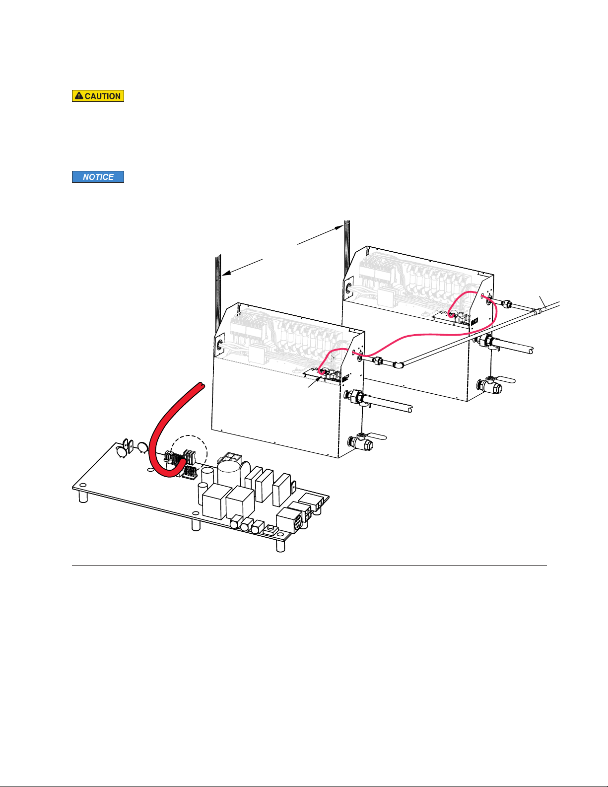
Secondary
Unit
Primary
Unit
Connector wires
will be reverse
color on secondary
generator
Power
Supply
Water
Feed Line
®
Installation, Operation & Maintenance Manuals
________________________________________________________________________
CONNECTING MULTIPLE GENERATORS
Applies to 1-2
1.
Install each unit as in a single installation. Install the genera-
ors as close to each other as possible while providing for all
t
clearances as shown on page 7.
2.
Shock hazard.
electrical supply before removing steam generator covers.
3. Connect the iSteam®, iTempo/Plus®or AirTempo®control to
either unit as per the Installation Manual supplied with each
control. The control must be connected to the primary unit.
Power must be disconnected at the main
Applies to 3-6
4. Connect the generators with a tandem cable as follows:
• Use Tandem Cable part number 103904 to connect two generators (cable is 12' long)
• Use Tandem Cable part number 103917 to connect 3-5 generators (cable is 30' long).
5. Remove one knock-out on each generator. Insert the ends of
interconnecting cable through the knock-outs.
Connect each end to the circuit board as shown.
6. Connect separate plumbing and power supplies for each unit.
I N S T A L L E R
Circuit Board
Components shown enlarged
for illustrative purposes.
Cable shown in red for clarity.
POST INSTALLATION
STEAM GENERATOR SYSTEM START-UP AND CHECKOUT
1. Turn the control ON. Follow specific instructions
2. Steam will begin to appear at the steamhead in
provided with the controls.
approximately 5 minutes (unless equipped with factoryinstalled Express Steam option). Steam will shut OFF
when desired temperature is reached and will automatically resume when room temperature drops below the
desired temperature.
3. Steam will shut OFF when control counts down to zero. To shut steam
off manually, turn control OFF. To clear steam from enclosure area, turn
shower ON before opening door.
4. If unit does not start and control does not turn ON (control display
does not light up) then turn breaker off for 20 seconds and try again.
5. Check all internal and external plumbing fittings for leaks while the
steam is ON.
15
Page 17
mr.steam
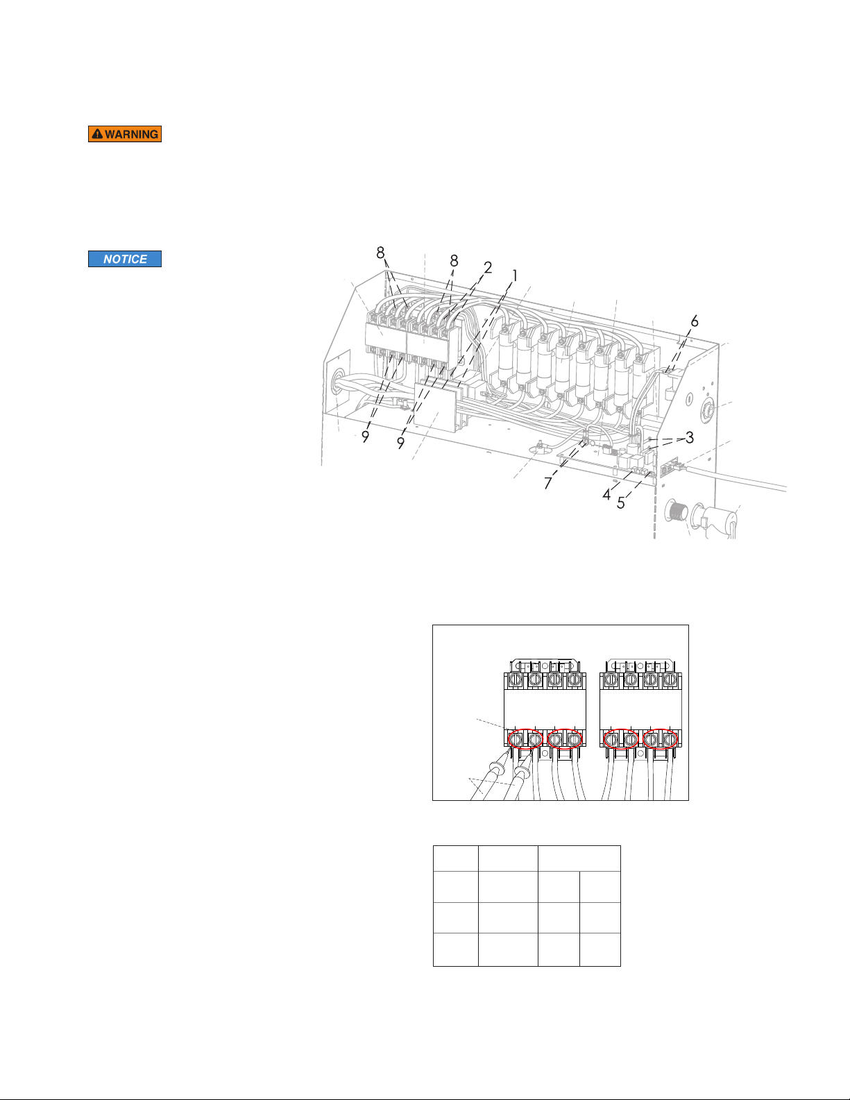
Safety Valve
Primary
T
ransformer
Secondary
Transformer
F
uses Control Board
W
ater Feed
Solenoid
Steam
Outlet
L
iquid
Level Probe
P
lug and Play
C
onnection
Primary
Contactor
Secondary
Contactor
Power
Supply
Knock-Out
P
ower Block
W
ater Inlet
Secondary
Contactor
Heating
Element Test
Points
Multimeter
Probes
Primary
Contactor
®
Installation, Operation & Maintenance Manuals
______________________________________________________________________________
TROUBLESHOOTING
Applies to 1-2
1. Electric shock hazard. MrSteam steam generators are connected to high voltage and
contain live electrical components. All installation and service to be performed by
qualified and licensed electricians only. Installation or service by unqualified persons
or failure to use MrSteam parts may result in property damage or in a personal injury.
2. Do not disassemble or service any components. Internal components contain no
serviceable parts.
The model and serial
number is printed on the data plate on
I N S T A L L E R
the front of the steam bath generator.
Please have this information available
when contacting Technical Services.
Note: Disconnect all connections
going to the steam generator.
When disconnecting the AutoFlush
connector, close manual drain valve.
Step 1 Check main incoming
power to the unit.
Step 2 Ensure the black wires from the primary side
of the transformer are connected to the quick connect tabs on the line side of the contactor.
Step 3 Verify that 24 VAC is coming
out of the transformer, WHITE & WHITE/BLUE wires,
into the circuit board.
Step 4 Verify that the green light
on the Circuit Board is ON.
Step 5 Push the white Force-On test button on the
circuit board (see page 17) to run the generator for
a 10 minute test cycle. Make sure the steam room
is empty.
Step 6 Verify 24 VAC to the water feed solenoid,
GRAY & WHITE/GRAY wires (will fill when needed).
Step 7 Temporarily short out the WLS (Purple wire)
and GROUND (Green wire) terminals and verify that
the contactor engages.
Step 8 When the red light is ON, verify 24 VAC,
RED & WHITE/RED wires, to the contactor.
Step 9 Check main voltage on the load side of the
contactor when it is engaged.
Step 10 If all steps on the power path were verified,
turn OFF power to the unit.
Step 11 Using multimeter, check the resistance
(ohms) of each heating element test point, as shown
in Resistance Range Chart.
The steam generator represented in this illustration is for reference purposes only. Please contact MrSteam for specific product information.
Contactor Test Points
Resistance Range Chart
Model Resistance
No. Voltage (V) Range (Ohms)
MX4E
MX5E
MX6E
16
208 7.8 9.5
240 10.4 12.7
208 6.5 7.9
240 8.6 10.6
208 5.2 6.3
240 6.9 8.4
Page 18
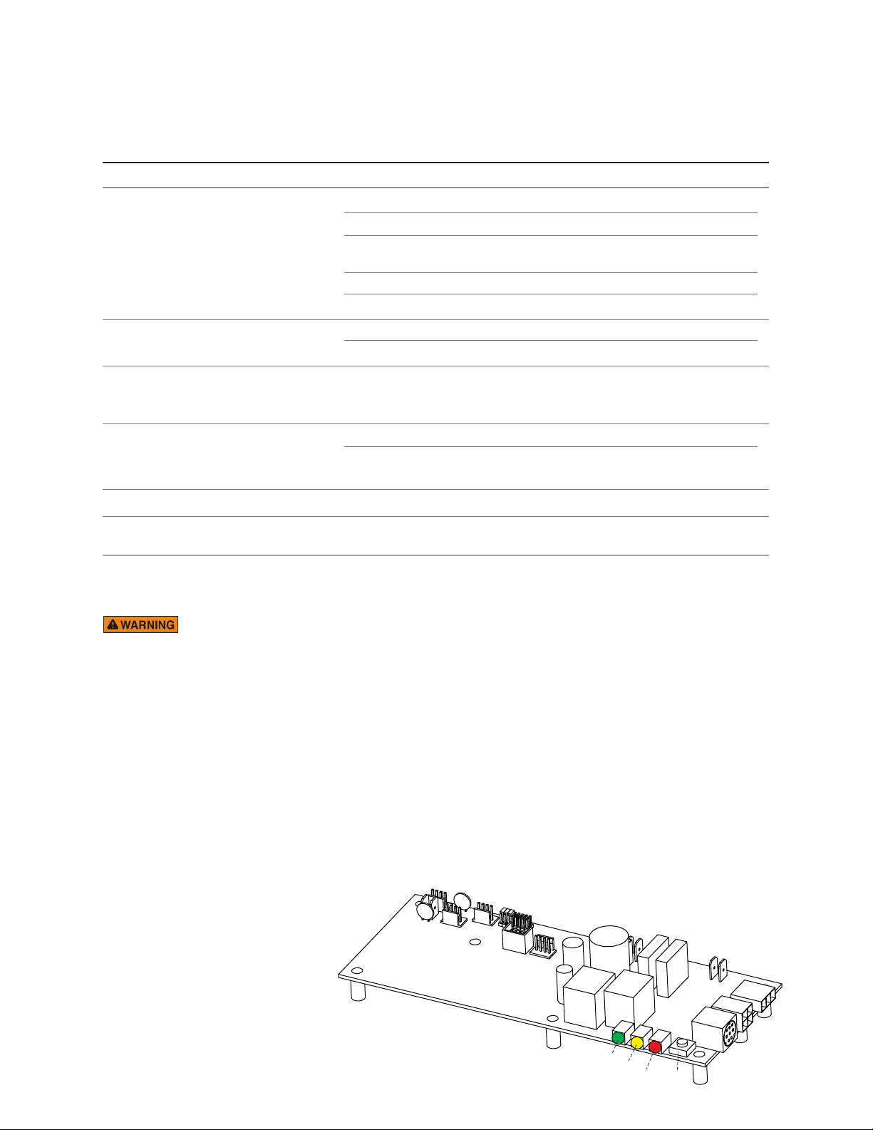
mr.steam
Force On
Test Button
Yellow
(Water Level)
Green
(Power)
Red
(Heater)
®
Installation, Operation & Maintenance Manuals
________________________________________________________________________
EXPLANATION OF THE STATUS CODES DISPLAYED ON THE CONTROL
The control (either iSteam®, AirTempo®, iTempo®or iTempo/Plus®) may display a status code if the steam generator
is not functioning properly.
Code Code Meaning Probable Cause Suggested Remedy
H20 Water level is not Water Supply is off Turn on Water Supply
satisfied within 5 minutes
Prr1 Temperature Probe Error Control cable/MSTS cable cut Replace control cable/MSTS
or Prr2
Err1 Incorrect Field Supply Voltage Incorrect voltage supplied Supply steam generator with the correct
(green light on Circuit Board to Generator voltage noted on the data plate label
will be off)
Err2 Button on control is pressed Control cover misalignment Remove and reinstall control cover
for more than 5 minutes
Defective water feed solenoid Check/replace water solenoid valve
Water feed probe not functioning Check/clean probe.
Check probe wiring
Drain Valve Open Check/Close drain valve
AutoFlush not functioning Check/Replace AutoFlush
Internal problem with control/MSTS Replace control / MSTS
Debris behind control cover Remove control cover and clean cover,
control and keypad with a damp cloth
I N S T A L L E R
Errb Water level not satisfied in a tandem set up - Check secondary generators, see H20.
Err7 Circuit Board malfunction Memory error in Circuit Board Press ON/OFF to clear.
Replace control if code remains
Additional Error Codes can be found in the control installation instructions.
EXPLANATION OF LED INDICATORS ON THE CIRCUIT BOARD
Electric shock hazard. MrSteam steam generators are connected to 240V line voltage and contain live electrical
components. All installation and service to be performed by qualified and licensed electricians and plumbers only. Installation or
service by unqualified persons or failure to use MrSteam parts may result in property damage or in a personal injury.
__________________________________________________________________________________________________________________________________________________
GREEN LED is ON when there is 208/240 Volt incoming power connected,
__________________________________________________________________________________________________________________________________________________
YELLOW Water level indicator–LED is OFF when no water is detected (for more than 5 seconds). ON when water level is
__________________________________________________________________________________________________________________________________________________
RED Contactor relay indicator–LED is ON when relay is closed and sending 24 Volts to the
__________________________________________________________________________________________________________________________________________________
FORCE ON Press this button to operate the generator. This button is for trouble shooting only and will operate
TEST BUTTON
__________________________________________________________________________________________________________________________________________________
24 Volt transformer secondary output and on-board 5 Volt DC control power are present.
satisfactory. For units with AutoFlush, if more than two hours have elapsed since last usage and the LED is ON
it is indicative of an AutoFlush or water level probe circuit malfunction. Except when the Express Steam is installed,
Express Steam units will refill after AutoFlush cycle.
contactor coil. (This LED comes ON if the generator is ON.)
if a control is connected or not. Pressing the button again will shut the generator OFF. The test button
will only allow the generator to operate for 10 minutes.
Circuit Board
PN 104288
(shown without wiring)
All drawings are for illustrative purposes only
17
Page 19
A S S E S S O R I E S
CONTROL INSTALLATION
Refer to Installation Instructions for the specific control
Applies to 1-7
1. Install the iSteam, AirTempo, iTempo or iTempo/Plus
controls according to installation instructions, provided with the controls. Failure to install according
to instructions will result in an inoperative control or
hazardous overheating or inadequate heating of the
steam room.
2.
The iSteam®,
controls are designed to be installed inside or outside the steam room as a matter of personal preference.
iTempoPlus control is installed outside the steam
room a Remote Temperature Probe (PN MSTS)
must be installed inside the steam room per installation instructions supplied with the Remote
Temperature Probe. Failure to install according to
instructions will result in an inoperative control and
overheating of the steam room.
Do not route iSteam,
3.
iTempo, HomeWizard or iGenie control wiring inside
conduit together with power lines or close to hot
water or steam piping. Doing so may result in an inoperative or hazardous installation.
4. Do not alter or modify any MrSteam product. Doing
so may result in an inoperative or hazardous installation and will void the UL listing and warranty.
5.
If the control is installed inside the steam room t
control must be located 4-5 feet above the floor
near the bather seating area. Failure to install the
control 4-5 feet above the floor may result in an
operative control and over or under heating of the
steam room.
6. The control features an integral temperature sensor.
Locate the control in a location representative of
the desired steam bathing temperatures. Do not
locate the control above or near the steamhead or
direct steam emissions. Locating the control near
the steamhead will not allow the temperature sensor to record the correct toom temperature and
result in inadequate heating.
7. Locate the control on a vertical wall.
AirTempo®,
If an iSteam, AirTempo, iTempo or
iTempo®and iTempoPlus
AirTempo,
iTempo/Plus,
he
Applies to 8-10
8.
To avoid unintentional steambath operation, do not locate the
control where other controls, accessories, shower heads, valves,
body sprays or similar within the shower could cause confusion or
interfere with the MrSteam control’s intended use and function.
9. Do not use any iSteam
HomeWizard
ing its own manual and the MrSteam steam generator Installation
and Operation Manual. Failure to read and understand these
instructions may result in an inoperative or hazardous installation.
10. Do not operate iSteam, AirTempo,iTempo/Plus, iTempo,
HomeWizard or iGenie controls with other than a MrSteam iSteam,
AirTempo, or iTempo compatible steam generator. MrSteam residential steam generators with serial numbers lower than 900000, or
any other brand of steam generator are not to be operated with
iTempo controls. Doing so may result in an inoperative or hazardous installation. If iSteam is used with a generator having serial
number less than 1174000, contact MrSteam technical support for
an upgraded PC board.
11. Turn power to the steam generator OFF before connecting any
control to the generator. Failure to turn the power off will result in
an inoperable control.
12. Discontinue use of the steam generator or control if the steam
generator is damaged or otherwise not functioning properly.
Operating a damaged steam generator may result in an inoperative or hazardous installation.
13.
The control cable should be run in a dedicated 1” conduit to
facilitate installation and service.
14. The standard control cable length is 30 feet. Ensure that the
control and/or steam generator are located accordingly.
Contact a MrSteam technical service representative if a 60 foot
cable is required. Excess control cable should be neatly coiled
and twisted into a figure 8.
®
Applies to 11-14
®
, AirTempo®, iTempo/Plus®, iTempo®,
or iGenie®controls without reading and understand-
30' Cable 60' Cable
Control
(standard) (optional)
iSteam 104117-30 104117-60
iTempoPlus 104117-30 103990-60
iTempo 104117-30 103990-60
AirTempo 104117-30 103990-60
18
Page 20
INSTALLER
Installation, Operation & Maintenance Manuals
®
All drawings are for illustrative purposes only
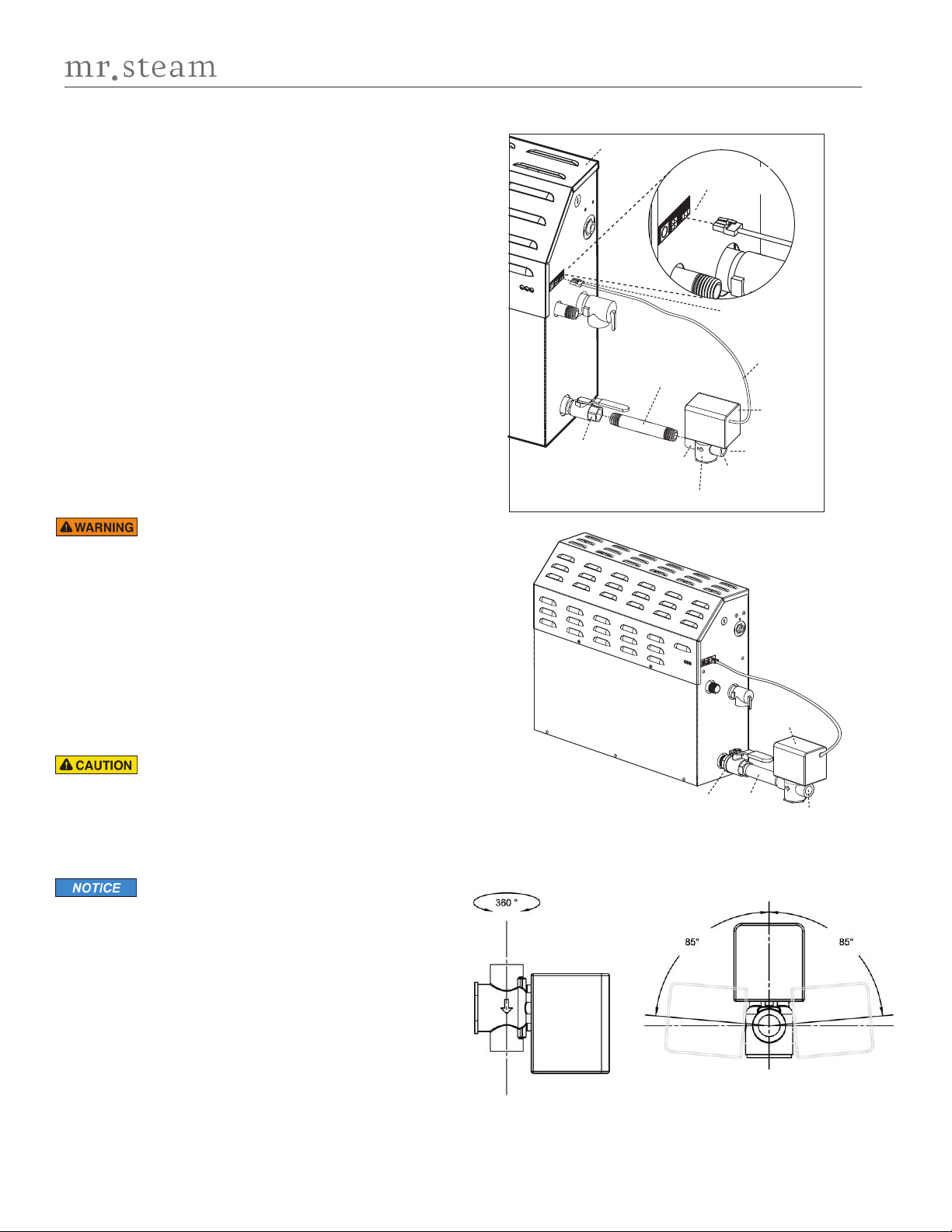
Drain Valve
DO NOT TURN OR REMOVE THE DRAIN VALVE
(shown in the correct open position)
Nipple
Plumb to
Drain Line
AutoFlush
Valve
AutoFlush Shown
Fully Assembled
AutoFlush Cord
AutoFlush
Valve
3 Pin Connector
for AutoFlush
AutoFlush Cord
Connector
Drain Valve
(shown in the correct
open position)
DO NOT REMOVE
THIS DRAIN VALVE
Steam Generator
End
"B"
End
"A"
Plumb to
Drain Line
Arrow indicates correct direction of flow
Steam Generator
Nipple
copper or brass
1" NPT x 3
1
⁄2" nipple or
longer
(not supplied)
OPTIONAL AUTOFLUSH
®
OPERATION
The optional AutoFlush automatically drains the generator
following each use. A time delay allows the water to cool down
(about two hours) before it drains by gravity for a safe and gentle
operation.
At the start of the flush cycle, the generator will drain and fill with
water at the same time. This flush cycle will continue for
approximately 5 minutes, then the generator will stop filling with
water and the AutoFlush valve will remain open until the next
steam session .
If the Express Steam® option has been installed, the AutoFlush will
drain for ten minutes then refill with fresh water to begin the preheat cycle.
INSTALLATION
SWEAT FITTINGS When using sweat fittings use only tin base
solder with a melting point below 600 degrees F. Do not overheat.
Ends of water supply tubing must be thoroughly clean for a
minimum distance of 1" from ends. Do not remove valve cover.
Applies to 1-4
1.
Do not connect the generator drain line to an undersink trap.
2.
Do not plumb the generator drain and condensation pan drain
together in such a way that will cause drain water to back into
condensation pan. Water backing up into the Drain Pan may
overflow and cause a leak and property damage.
3.
Do not drain into a steam enclosure or any location where
accidental contact with drain water may occur. In the event of a
power failure the AutoFlush valve will open and may discharge
boiling water causing a scalding hazard.
4.
Do not connect the drain valve to the steam piping. Connecting
the drain line to the steam piping may allow boiling water to
discharge through the steamhead causing a scalding hazard.
5.
Do not remove the drain valve. Removal may cause equipment
and property damage. If there is not enough room for the valve,
an elbow and a short nipple (not provided) can be added.
6.
The AutoFlush valve must be installed within the orientation
range shown.
7.
A drain valve is provided to facilitate maintenance and
servicing. Provide a drain line connection from steambath
Applies to 7-1 8
generator drain valve according to National and Local Codes.
8.
Check local plumbing code for receptor, trap and vent
requirements.
9.
Do not connect Drain line and Safety Valve line together.
(Contained on next page)
19
Page 21
mr.steam
______________________________________________________________________________
10.
The steam generator drains by gravity. Plumb all drain lines accordingly.
11.
The Drain is open when the Drain Valve handle is aligned with brass nipple.
12.
Connect the AutoFlush cord connector to the three pin connector as shown.
13.
Plumbing to be performed by a qualified plumber and shall be in accordance with
applicable national and local codes.
14.
Unit drains by gravity. A drain line that is lower than the AutoFlush® assembly must be available.
15.
The AutoFlush valve outlet is 1“ NPT.
16.
Use copper or brass nipple 1“ NPT x 31⁄2“ or longer (not supplied) to connect AutoFlush valve
I N S T A L L E R
(end "B") to the Drain Valve (valve end “A” and “B” are indicat-ed on bottom of AutoFlush Valve).
17.
An arrow on the AutoFlush valve indicates the correct direction of flow.
18.
To Check Operation:
1.
Turn ON control and allow tank to fill with water.
2.
Turn OFF control. Water should stay in tank.
3.
Turn OFF power at the panel box. Water should discharge from tank.
4.
Turn ON power at panel box.
5.
Repeat.
®
Installation, Operation & Maintenance Manuals
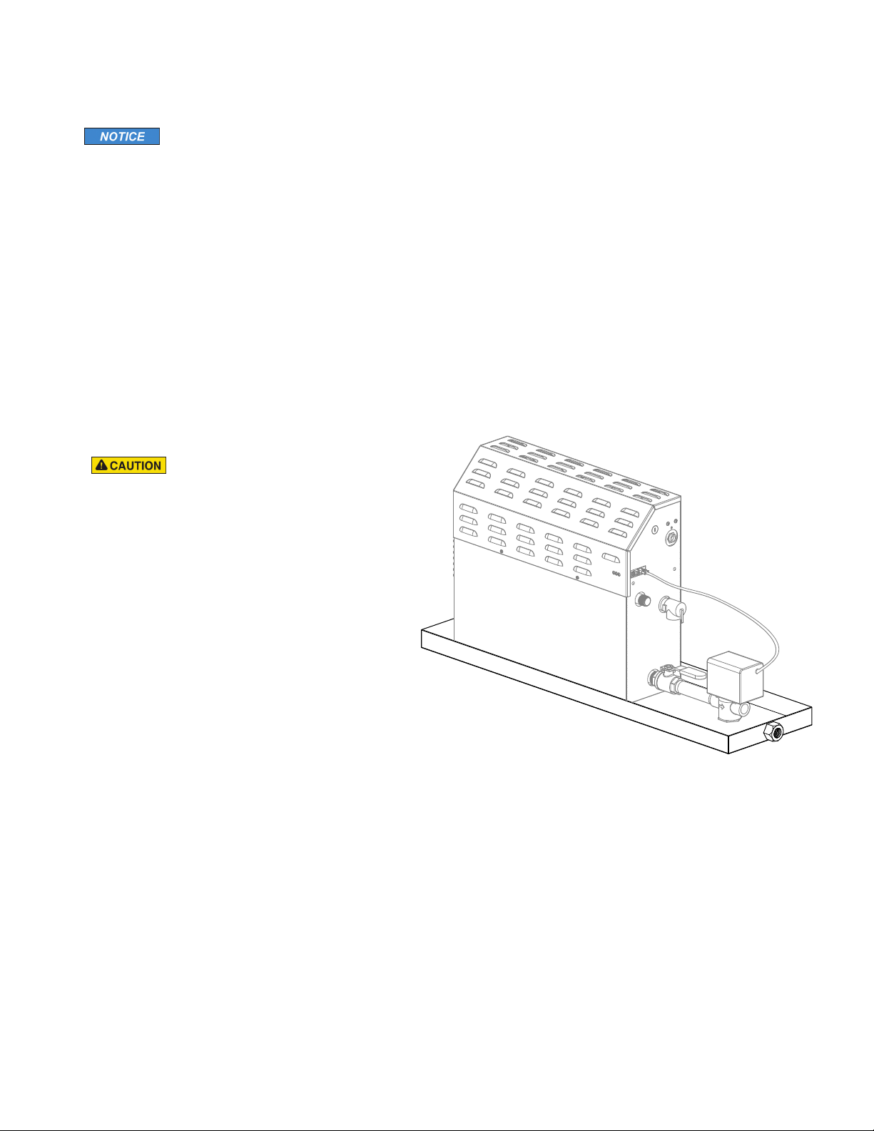
OPTIONAL CONDENSATION
Applies to 1-7
1. MrSteam strongly recommends the use of a condensation
pan in the unlikely event of a plumbing leak.
2. Locate the condensation pan on a solid level surface
and place the steam generator inside the condensation
pan. Ensure the steam generator is level (see page 5
for locating the steam generator).
3. All plumbing shall be performed by a qualified licensed
plumber and in accordance with applicable national
and local codes. Check local plumbing code for
receptor, trap and vent requirements.
4. Condensation pans drain by gravity.
5. The condensation pan is equipped with an integral female
fitting for connection to the drain.
6. Do not plumb the generator drain and condensation pan
drain together in such a way that will cause drain water to back
into condensation pan and cause a leak and property damage.
7. See pages 10-11 for complete drain line and plumbing instructions.
PAN
3
⁄4" NPT
20
Page 22

mr.steam
®
Installation, Operation & Maintenance Manuals
________________________________________________________________________
IMPORTANT!
tion of the residential steam generator. MrSteam offers numerous options and accessories for use with the steam generator. Some of the options and accessories must be considered when installing the steam generator as they require special
plumbing, electrical or space accommodations. Please use the chart below to identify which options and accessories must
be considered during steam generator installation.
ccessory/Options Part No. Impact on Steam Generator
A
AromaSteam Fragrance Pump MSAROMA Plumbing line 6 ft. cable length
iSteam3 Control iSteam3-BK Limited by 30 ft. or 60 ft. cable
AirTempo Control AIRTBK +
iTempo Control MSITEMPORD + Designer Code* Limited by 30 ft. or 60 ft. cable
iTempo/Plus Control MSITPLUSRD + Designer Code* Limited by 30 ft. or 60 ft. cable
Linear Steam Head 104216, 104217 Plumbing
Home Wizard HOMEWIZARD-BLK Limited by 30 ft. or 60 ft. cable
ChromaSteam3 MSCHROMA3-BK Limited by 60 ft. cable
Color Lighting MSCHROMA3-WH
This Installation, Operation and Maintenance Manual includes information for safe and reliable installa-
iSteam3-WH
Designer Code* Consider wireless range, maximum range is 60 ft.
AIRTWH + Designer Code*
MSITEMPOSQ + Designer Code*
MSITPLUSSQ + Designer Code*
HOMEWIZARD-WH
CHROMA3DUOBK
CHROMA3DUOBK
CHROMA3DUOWH
I N S T A L L E R
AudioSteam Music Experience MSAS3 Limited by 60 ft. cable
SteamLinx App Module STEAMLINX Limited by 60 ft. wireless range between modules
* Designer Codes:
PC= Polished Chrome PN = Polished Nickel BN=Brushed Nickel PB= Polished Brass BB=Brushed Bronze
ORB=Oil Rubbed Bronze SB=Satin Brass MB=Matte Black WH=White Glass Fascia BK=Black Glass Fascia RAW=Raw
21
Page 23
mr.steam
®
Installation, Operation & Maintenance Manual
__________________________________________________________________________
H O M E O W N E R S E C T I O N
IMPORTANT SAFETY INFORMATION
As you follow these instructions, you will notice warning and caution symbols. This blocked information is important for the safe and efficient
installation and operation of this steam bath system. These are types of potential hazards that may occur during installation and operation:
Indicates a potentially hazardous situation, which, if not avoided, could result in death or serious injury.
ndicates a potentially hazardous situation, which, if not avoided may result in minor or moderate injury or product damage.
I
This highlights information that is especially relevant to a problem-free installation.
All information in these instructions is based on the latest product information available at the time of publication. Sussman-Automatic Corporation
reserves the right to make changes at any time without notice. More current instructions may be available at
www.mrsteam.com.
Applies to 1-17
1. Steam rooms contain steam and elevated temperatures.
Please read and observe all warnings in this manual
before using a steam room.
2. Discontinue use of the steam generator and control if the
steam generator or control are damaged or otherwise
not functioning properly. Using damaged equipment may
result in an inoperative or hazardous installation
3. The MAX series of steam generators are for residential
use only. Commercial or other nonresidential applications
void the warranty and may adversely affect product
performance and may represent a safety hazard.
4. Read these instructions before installation, operation or
service.
5. Although the MAX steambath generators have been fully
qualified for shipment by MrSteam, the following must
be reviewed for proper, safe and enjoyable steam
bathing:
- Verify that the model and accessories specifications are
correct for the incoming line voltage.
- Ensure steambath generator has been correctly sized for
the steam room. Pay particular attention to room volume
and construction. If any questions, please refer to
MrSteam sizing and selection guide on page 6 or call
MrSteam.
6. Supervise children at all times.
7. Steam is hot and can cause injury or death if improperly
used.
8. Prolonged use of the steam system can raise excessively
the internal human body temperature and impair the
body’s ability to regulate its internal temperature (hyperthermia). Limit your use of steam to 10-15 minutes until
you are certain of your body’s reaction.
9. Excessive temperatures have a high potential for causing
fetal damage during the early months of pregnancy.
Pregnancy or possibly pregnant women should consult a
physician before using a steam bath.
10. Obese persons and persons with a history of heart disease, low or high blood pressure, circulatory system
problems, or diabetes should consult a physician before
using a steambath.
11. Persons using medication should consult a physician
before using a steambath since some medication may
induce drowsiness while other medications may affect
heart rate, blood pressure and circulation.
12. Electric shock hazard. MrSteam steam generators are
connected to high voltage and contain live electrical
components. All installation and service to be performed by qualified and licensed electricians and
plumbers only. Installation or service by unqualified
persons or failure to use MrSteam parts may result in
property damage or in a personal injury.
13. If you are pregnant, have a coronary condition, are in
poor health, are being treated for any other medical
condition, or are using medication or drugs, MrSteam
recommends that you obtain the approval of a physician before use. For information about this product and
safety issues, call 1.800.76.STEAM.
14.
Do not install or use any iSteam®, AirTempo®, TempoPlus®,
®
iTempo
ing and understanding the Control Installation and
Operation Manual. Failure to read and understand these
instructions may result in an inoperative or hazardous
installation.
15. If an iSteam, AirTempo, iTempo or iTempo/Plus control is
installed outside the steam room a Remote Temperature
Probe (PN MSTS) must be installed inside the steam room
per installation instructions supplied with the Remote
Temperature Probe. Failure to use a Remote Temperature
Probe or failure to install according to instructions will
result in an inoperative control and overheating of the
steam room.
16. To prevent slip and fall hazards non-slip strips must be
installed on the steam room floor.
17. Do not alter or modify any MrSteam product. Doing so
may result in an inoperative or hazardous installation and
will void the warranty.
, HomeWizard®or iGenie®controls without read-
22
Page 24
mr.steam
®
Installation, Operation & Maintenance Manuals
_________________________________________________________________________
IMPORTANT SAFETY INFORMATION (cont.)
Applies to 14-17
14. The wet surfaces of steam enclosures may be slippery. Use care when entering or leaving.
15. The steamhead is hot. Do not touch the steamhead
and avoid the steam near the steamhead.
16. The information in this manual should be used in
conjunction with consultations with an architect,
designer and contractor in determining factors necessary in providing a suitable and safe steam room.
17. MrSteam steam generators are intended to be
operated with MrSteam controls and accessories
only, and are to be installed strictly in accordance
with the specific instructions contained in this manual and as supplied in the manuals provided with the
controls or accessories.
Applies to 18-22
18. This document contains important safety, operation
and maintenance information. Do not discard this
document.
19. Read the Installation and Operation Manual of all
controls and accessories available at
www.mrsteam.com.
20. Record the model and serial number of the steam
generator in the space provided in the table of
contents of this manual.
21. If acrylic, fiberglass or other non-heat resistant
materials are used as part of the steam room enclosure consult with the material manufacture and see
page 12, "Steamhead Installation" for additional
details.
Carefully inspect the steam generator and packaging
22.
for shipping damage. In the event of shipping damage, please contact the carrier for claim information.
MrSteam customer service department can assist you
with any missing or damaged parts.
HYPERTHERMIA
body reaches a level several degrees above the normal body
temperature of 98.6° F. The symptoms of hyperthermia include
an increase in the internal temperature of the body, dizziness,
lethargy, drowsiness, and fainting. The effects of hyperthermia
include:
a) Failure to perceive heat;
b) Failure to recognize the need to exit the steambath;
c) Unawareness of impending risk;
d) Fetal damage in pregnant women;
e) Physical inability to exit the steambath
f) Unconsciousness.
The use of alcohol, drugs, or medication can greatly increase
the risk of hyperthermia.
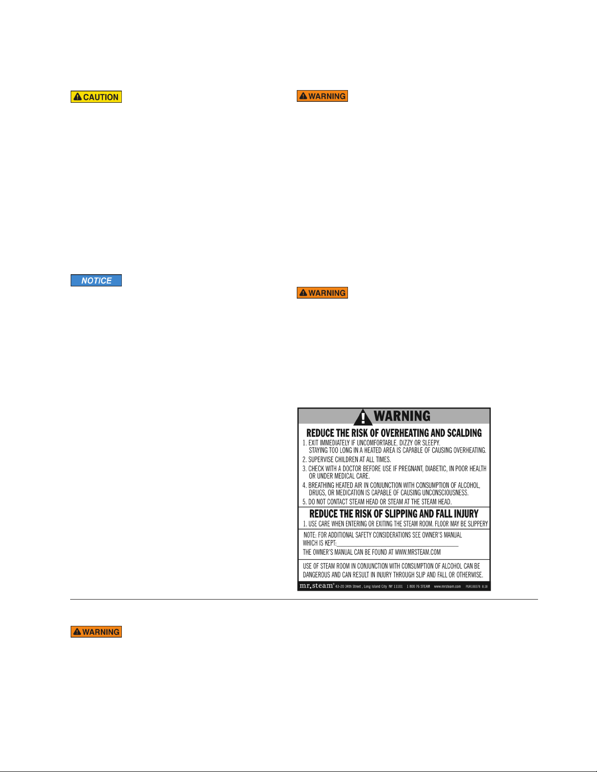
The manual supplied with the generator includes a
peel and stick warning label. Its proper use is an essential part of
providing a safe environment for steam room users. The peel and
stick warning label must be applied to the wall of the shower or
steam enclosure, at a point that is visible to all users. Failure to install
this sticker may result in serious injury or death. The location where
this owner's manual is kept shall be written in the space provided on
the label using permanent ink. For a replacement warning label
contact MrSteam customer service at1-800-76-STEAM or
[email protected].
occurs when the internal temperature of the
H O M E O W N E R
SETTING THE STEAM BATH TEMPERATURE AND DURATION
Set the steam bathing temperature according to personal preference, however it is highly
recommended to begin steam bathing at a low temperature setting to gauge comfort and safety levels.
Set duration to a maximum of 10 minutes to gauge comfort and safety levels. This will allow the steam
generator to heat up and begin producing steam while providing a short steam bath session.
23
Not Actual
Size
Page 25
mr.steam
®
Installation, Operation & Maintenance Manual
__________________________________________________________________________
CARE TIPS FOR ALL CONTROLS
AND STEAMHEADS
1. Use only mild soap and water on a soft cloth
to clean the control and steamhead.
2. Do not use abrasive cleansers.
3. If the decorative cover is damaged on
the iTempo or iTempo/Plus call MrSteam
technical service for replacement parts.
Replacement of the decorative
covers requires removal and reinstallation of the
control from the mounting surfaces.
H O M E O W N E R
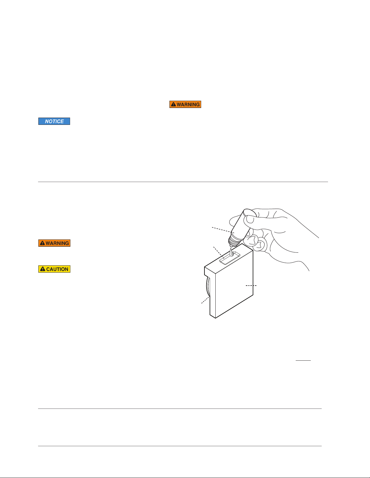
USING MrSteam ESSENTIAL OILS
Enjoy AromaSteam essential oils by placing a drop or two
into an unheated AromaSteam steamhead as shown in the
illustration. Only use MrSteam AromaSteam essential oils in
the MrSteam AromaSteam steamhead.
STEAM GENERATOR MAINTENANCE
MrSteam steambath generators require little maintenance. Other
than periodic draining, maintenance procedures are minimal. Every 2
months, or more often in “hard” water areas, the manual drain valve
should be opened fully flushing out accumulated materials, salts and
other particles which are natural by-products of boiling water.
Applies to 1-2
1. Draining immediately after a steam cycle may
expose PVC and other piping to high temperature water.
Check local codes. The unit will refill automatically when the
control is activated again. In areas of hard water, a MrSteam
AutoFlush
2. Failure to allow the water to cool will expose the equipment and
user to scalding water and cause property and personal injury.
Flush a minimum of 8 hours after the control has been turned off
to insure that the water has cooled.
®
system is recommended for generator longevity.
AromaSteam
10 ml bottle
with integrated
dropper
Essential oils and/or aroma therapy can
cause inflammation, burns, headache, nausea and allergic
reactions. Consult a physician before using aromatherapy.
Applies to 1-6
1. Use essential oils with caution. Essential oils are for
external use only. Keep out of reach of children.
Essential oils are highly concentrated and are potent
substances and should not be applied directly to the
skin as they can be irritants. Use essential oils with
caution.
2. Place the drops into the MrSteam AromaSteam steamhead recess prior to turning on the steambath. Do not
place drops in a hot steamhead as serious injury can
result if you do not follow this warning.
3. Start with one drop to gauge strength and suitability.
Limit to a maximum of a few drops for a steam bathing
session.
4. The bather should exit the steambath immediately if
dizziness occurs. If skin irritation occurs stop using the
oils immediately. Remove any excess oil by washing in
Recess for
essential oil
Steam
emission
slot
mild soap and water. If ingested, rinse mouth with water.
Administer water or milk to dilute. Contact a physician
immediately.
5. Aromatic oils should be added to steamhead before
ing on the steambath unit. DO NOT add oil during steam
bathing or when the steamhead is heated.
6. Tightly close bottles when storing oils. Keep bottles away
from sources of ignition.
WARRANTY
To view or download the MrSteam Residential Generator Warranty
AromaSteam steamhead
(install per instructions
on page 12)
turn-
and register your Product go to:
www.mrsteam.com
24
Page 26

®
mr
steam
.
®
Feel Good Inc.
www.mrsteam.com
Products, information and specifications are subject to change without notice.
Please call Technical Support at 1.800.76.STEAM (East Coast) or 1.800.72.STEAM (West Coast) for more information.
The model and serial number is printed on the data plate on the front of the steam bath generator.
Have this information available when contacting Technical Service.
mr.steam
43-20 34th Street, Long Island City, NY 11101 TEL : 1 800 76 STEAM I 9410 S. La Cienega Blvd. Inglewood CA 90301 TEL : 1 800 72 STEAM
2020 © Sussman-Automatic Corporation I MrSteam and des., A Lifetime of Pleasure, AirTempo, AromaFlo, AudioWizard, AutoFlush, AutoSteam, Butler Package, ChromaSteam, Clean Steam...Every Time,
Club Therapy, CT Day Spa, Digital 1, Express Steam, Feel Good Inc., From Bathroom to Spa, HomeWizard, iButler, iGenie, iSpa Package, iSteam, iTempo, iTempo/Plus, Linear Steamhead, Making
Wellness a Way of Life, Music Therapy, My Steam, SmartSizing, Spa Package, Steam Genie, Steam on Demand, Steam in a Box, Steam@Home, SteamStart, SteamTherapy, Sussman, Tala, Tala Bath &
Body, Tempo, The Intelligent Steambath, Valet Package, and Virtual Spa System are registered trademarks of Sussman-Automatic Corporation.
®
Sussman-Automatic Corporation
®
I
PUR 100420A Rev 1.21
 Loading...