

Federal Signal Corporation WV450XL Series Installation And Maintenance Instructions Manual
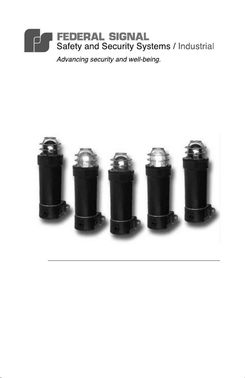
Model WV450XL Series
GRP LED Beacon
for Use in Hazardous and Marine Locations
*magenta and yellow not shown
Installation and
25500104A
Rev. A0 1113
Printed in U.S.A.
Maintenance Instructions
Warranty – Seller warrants all goods for ve years on parts and 2-1/2 years
on labor, under the following conditions and exceptions: Seller warrants that
all goods of Seller's manufacture will conform to any descriptions thereof
for specications which are expressly made a part of this sales contract and
at the time of sale by Seller such goods shall be commercially free from
defects in material or workmanship. Seller reserves the right at the Seller’s
discretion to “Repair and Return” or “Replace” any item deemed defective
during the warranty period. This warranty does not cover travel expenses,
the cost of specialized equipment for gaining access to the product, or labor
charges for removal and reinstallation of the product. This warranty shall be
ineffective and shall not apply to goods that have been subjected to misuse,
neglect, accident, damage, improper maintenance, or to goods altered or
repaired by anyone other than Seller or its authorized representative, or if
ve years have elapsed from the date of shipment of the goods by Seller with
the following exceptions: lamps and strobe tubes are not covered under this
warranty. Outdoor warning sirens and controllers manufactured by Federal
Warning Systems are warranteed for two years on parts and one year on labor.
No agent, employee, representative or distributor of Seller has any authority
to bind the Seller to any representation, afrmation, or warranty concerning
the goods and any such representation, afrmation or warranty shall not be
deemed to have become a part of the basics of the sales contract and shall
be unenforceable. THE FOREGOING WARRANTIES ARE EXCLUSIVE
AND IN LIEU OF ALL OTHER WARRANTIES OR MERCHANTABILITY,
FITNESS FOR PURPOSE AND OF ANY OTHER TYPE, WHETHER
EXPRESS OR IMPLIED. These warranties shall not apply unless Seller
shall be given reasonable opportunity to investigate all claims for allegedly
defective goods. Upon Seller's instruction a sample only of allegedly defective
goods shall be returned to Seller for its inspection and approval. The basis of
all claims for alleged defects in the goods not discoverable upon reasonable
inspection thereof pursuant to paragraph 8 hereof must be fully explained
in writing and received by Seller within thirty days after Buyer learns of the
defect or such claim shall be deemed waived.
Industrial Systems
2645 Federal Signal Drive • University Park, IL 60484-3167
Tel: 708-534-4756 • 877-289-3246 • Fax: 708-534-4852
Email: elp@federalsignal.com • www.federalsignal-indust.com • www.fs-isys.com

Model WV450XL Series
Contents
Safety Messages to Installers and Users ............................................. 5
Overview of Model WV450XL Series .................................................... 6
Certication ............................................................................................. 7
Unpacking the Beacon .......................................................................... 8
Mounting the Beacon ............................................................................. 8
Safety Messages for Wiring ................................................................... 9
Wiring the WV450XLD Flameproof Models ........................................ 10
Wiring the 24 Vdc Model WV450XLD ............................................11
Wiring the 110-220 Vac Model WV450XLD
Wiring the WV450XLE Increased Safety Models ............................... 13
Wiring the 24 Vdc Model WV450XLE ........................................... 15
Wiring the 110-220 Vac Model WV450XLE
Changing the Flash Pattern ................................................................. 16
.................................. 12
................................... 16
Safety Messages to Maintenance Personnel ..................................... 19
Maintaining the Beacon ....................................................................... 20
Cleaning the Enclosure .................................................................... 20
Replacing the LED Array
Ordering Accessories and Replacement Parts ................................. 23
................................................................. 21
3

Model WV450XL Series
Contents
Figures
Figure 1 Mounting hole locations Ex d version ....................................... 8
Figure 2 Mounting hole locations Ex de version ..................................... 9
Figure 3 Connections for 24 Vdc model ............................................... 11
Figure 4 Connections for for 110-220 Vac model ................................. 13
Figure 5 Terminal block for Model 450XLE ........................................... 14
Figure 6 Connections Ex de DC or AC beacons...................................15
Figure 7 Location of DIP switch for ash patterns ................................ 18
Tables
Table 1 SW1 settings for ash patterns ................................................ 18
Table 2 Replacement parts ................................................................... 23
© 2013 Federal Signal Corporation. All rights reserved.
4
Installation and Maintenance Instructions
Safety Messages to Installers and Users
It is important to follow all instructions shipped with this product.
This device is to be installed by a trained electrician who is
thoroughly familiar with and will follow all applicable national and
local codes in the country of use.
This device should be considered a part of the warning system and not
the entire warning system.
The selection of the mounting location for the device, its controls and
the routing of the wiring are to be accomplished under the direction
of the facilities engineer and the safety engineer. In addition, listed
below are some other important safety instructions and precautions
you should follow:
• Read and understand all instructions before installing or operating
this equipment.
• The circuitry of the beacon can be damaged by an electrostatic
discharge. Follow antistatic procedures while installing the
beacon.
• Never alter the unit in any manner. Safety in hazardous locations
may be endangered if additional openings or other alterations are
made in units specically designed for use in these locations.
• Do not connect this beacon to the system when power is on.
• After installation, ensure that all threaded joints are properly
tightened.
• Keep the unit tightly closed when in operation.
• After installation, test the beacon system to ensure that it is
operating properly.
• After testing is complete, provide a copy of this instruction sheet
to all personnel.
• Establish a procedure to routinely check the beacon system for
proper activation and operation.
Model WV450XL Series
5

Installation and Maintenance Instructions
Failure to follow all safety precautions and instructions may result in
property damage, serious injury, or death.
Overview of Model WV450XL Series
The Federal Signal Model WV450XL Series is ideally suited for
explosive atmospheres and harsh environments. It is designed to serve
the demanding needs of offshore marine and land based industrial
applications. The housing is made of corrosion resistant components,
which dramatically reduces the cost of long-term maintenance.
The WV450XL Series beacons use all of the latest techniques in
non-metallic housing construction. The body of the product is
glass reinforced polyester (GRP) and 316 stainless steel hardware.
The use of GRP in the design improves corrosion resistance and
reduces weight as compared to traditional metal housings. The GRP
construction also saves time and money over the life of the product by
reducing or, in most cases, completely eliminating the need to perform
regular eld inspections of the ame path.
The WV450XL Series comes standard with metric entries, a 316
stainless steel dome guard and an extended life LED emitter.
The ameproof “D” versions come standard with a 316 stainless
steel mounting brackets and two M20 entries for eld cable gland
connections. The increased safety “E” versions have the added feature
of a terminal chamber with three M20 entries. The increased safety
design allows for quick eld termination and pass-through wiring.
There are seven dome colors: amber, blue, clear, green, magenta, red,
and yellow.
Product features:
• 316 stainless steel mounting bracket included
• Available voltages: 24 Vdc and 110-220 Vac
• Eight selectable ash patterns (Table 1 on page 18)
• Corrosion resistant GRP (glass reinforced polyester) housing
• Included dome guard
6
Model WV450XL Series
Installation and Maintenance Instructions
• M20 entries standard
• Body color natural black
• IP66 rated
• Zone 1 rated, IECEx, ATEX, Ex d IIB +H2 T6 Gb, Ex de IIB +H2
T6 Gb
Certication
Certicate Nos.: ATEX Cert No.: UL DEMKO 06 ATEX04259693X
IECEx Cert No.: IECEx UL 06.0010X
ATEX coding: II 2
Protection: Ex d IIB+H2 T6 Gb [-55°C ≤Ta≤ 55°C]
Ex de IIB+H2 T6 Gb [-20°C ≤Ta≤ 55°C]
Standards: EN60079-0: 2012, EN60079-1: 2007, EN60079-7: 2007.
IEC60079-0: 5th Ed., IEC 60079-1 6th Ed., IEC 60079-7:
4th Ed.
Special Conditions for Safe Use:
1) Potential electric static charging hazard. Use only a water
dampened cloth when cleaning the exterior of the unit.
2) The capacitance value of unearthed metal parts is 10 pF, when
measured per IEC/EN 60079-0.
3) Contact the manufacturer for information on the dimension of the
ameproof joints.
Condições especiais para o uso seguro:
1) Perigo de potencial carga eletroestática. Ao limpar a parte
externa da unidade, utilize apenas um pano úmido.
2) O valor de capacitância de peças metálicas desenterradas é
10 pF, quando medido por IEC / EN 60079-0.
3) Contate o fabricante para obter informação sobre a dimensão
das juntas à prova de fogo.
Model WV450XL Series
7
Installation and Maintenance Instructions
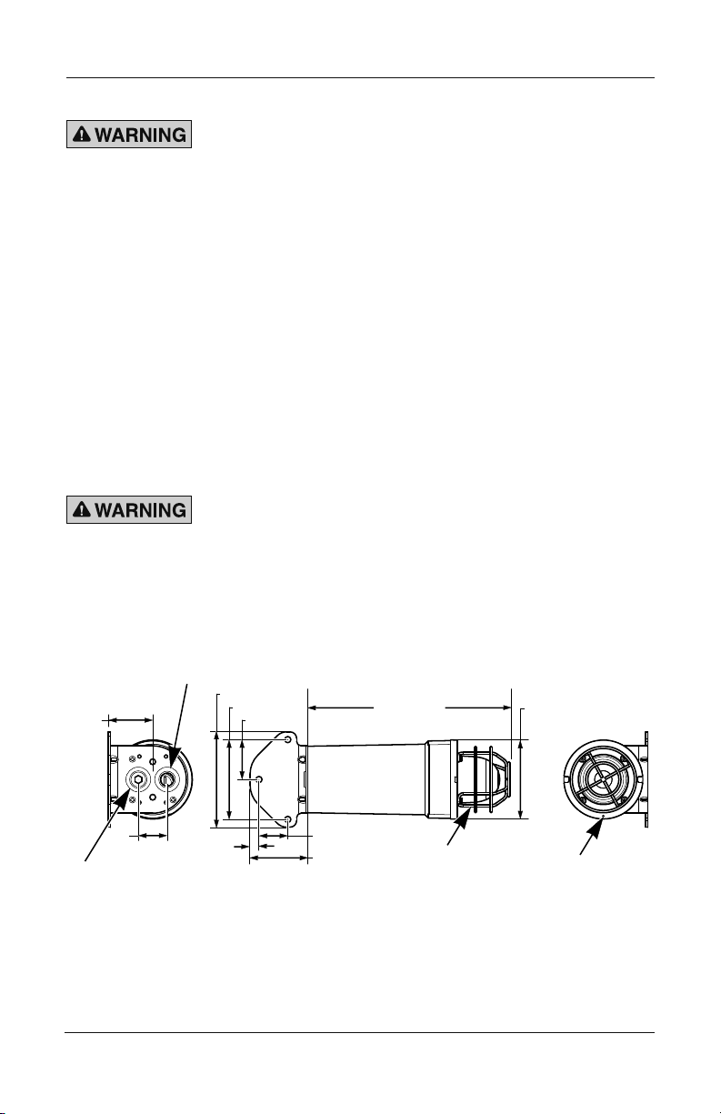
Ex d VERSION
GRUB SCREW
Unpacking the Beacon
EXPLOSION HAZARD—Damaged dome covers can lead to
explosions that could result in serious injury or death. Replace
damaged dome covers.
After unpacking the beacon, examine it for damage that may have
occurred in transit. If it has been damaged, do not attempt to install or
operate it. File a claim immediately with the carrier, stating the extent
of the damage. Carefully check all envelopes, shipping labels, and tags
before removing or discarding them. Disposal of all shipping materials
must be carried out in accordance with national and local codes and
standards. If any parts are missing, please call Federal Signal Customer
Support at +1 708-534-4756 or +1 877-289-3246.
Mounting the Beacon
SECURE TO FLOOR OR WALL—To prevent injury, this apparatus
must be securely attached to the oor or wall in accordance with
the installation instructions.
ø39.4 [ø1.55] X 2
8
63.5 [2.50]
41.3 [1.63]
Figure 1 Mounting hole locations Ex d version
M20 GLAND ENTRY
2 POSITIONS
12.7 [0.50]
136.5 [5.37]
114.3 [4.50]
57.2 [2.25]
41.3 [1.63]
82.6 [3.25]
289.7 [11.41]
GUARD
Model WV450XL Series
113.3 [4.46]
LENS COVER ASSY
 Loading...