

Federal Signal Corporation VISIBEAM II Installation, Operation And Maintenance Instructions

2561083A
REV. A 801
Printed in U.S.A.
INSTALLATION, OPERATION AND MAINTENANCE INSTRUCTIONS
FOR
VISIBEAM® II REMOTE CONTROLLED SPOTLIGHT
SAFETY MESSAGE TO INSTALLERS AND USERS
People’s lives depend on your safe installation of our
products. It is important to read, understand and follow all
instructions shipped with the products. In addition, listed
below are some other important safety instructions and
precautions you should follow:
• To properly install this kit: you must have a
good understanding of automotive electrical
procedures and systems, along with proficiency
in the installation and use of safety warning
equipment.
• DO NOT install equipment or route wiring or
cord in the deployment path of an air bag.
• When drilling into a vehicle structure, be sure
that both sides of the surface are clear of anything that could be damaged.
• In order for the light to function properly, a
separate ground connection must be made. If
practical, it should be connected to the negative
battery terminal. At a minimum, it may be
attached to a solid metal body or chassis part
that will provide an effective ground path as
long as the light system is to be used.
• Locate light control so the VEHICLE and CONTROL can be operated safely under all driving
conditions.
• Do not attempt to activate or deactivate light
control while driving in a hazardous situation.
• You should frequently inspect the light to ensure that it is operating properly and that it is
securely attached to the vehicle.
• File these instructions in a safe place and refer
to them when maintaining and/or reinstalling
the product.
Failure to follow all safety precautions and instructions may result in property damage, serious injury, or
death to you or others.
I. UNPACKING.
After unpacking the unit, inspect it for damage that
may have occurred in transit. If the unit has been damaged, file a claim immediately with the carrier, stating the
extent of damage. Carefully check all envelopes, shipping
labels, and tags before removing or destroying them.
Ensure that the parts listed in the appropriate KIT
CONTENTS LIST are contained in the package.
II. KIT CONTENTS LIST.
ALL SURFACE MOUNT MODELS
Qty. Description
4 Screw, #6
3 Screw, #10, Hex
3 Flat Washer, #10
1 Gasket, Mounting
1 Plate, Mounting
1 Velcro Loop
1 Velcro Hook
ALL PIPE MOUNT MODELS
Qty. Description
4 Screw, #6
1 Plate, Mounting
1 Velcro Loop
1 Velcro Hook
ALL MAGNETIC MOUNT MODELS
Qty. Description
1 Cover, Magnet
1 Label, Caution
4 Screw, #6
1 Plate, Mounting
1 Velcro Loop
1 Velcro Hook
III. CONTROL INSTALLATION.
WARNING
When installing equipment inside air bag equipped
vehicles, the installer MUST ensure that the equipment is installed ONLY in areas recommended by
the vehicle manufacturer.
Failure to observe this warning will reduce the
effectiveness of the air bag, damage the air bag, or
potentially damage or dislodge the equipment,
causing serious injury or death to you or others.
A. Hook-and-Loop Mounting.
NOTE
The hook-and-loop mounting method is intended for
storing the control unit when it is not in use. The
hook-and-loop material may not provide sufficient
rigidity for proper control unit operation.
1. Locate a suitable mounting location for the
control unit.
NOTE
The hook-and-loop pads’ mounting surfaces must be
clean and dry for proper adhesion. If necessary, use
isopropyl alcohol and water to clean the mounting
surfaces.
4. Secure the mounting plate to the mounting
surface using the #6 thread-forming phillips screws.
5. To attach the control unit to the mounting
plate, align the mounting studs with the stud retainers and
press the control unit until it snaps in position.
2. Remove the paper backing from the hook pad
and affix it to the back of the control unit.
3. Remove the paper backing from the loop pad
and affix it to the mounting surface.
4. Place the control unit in position by mating
the hook and loop surfaces.
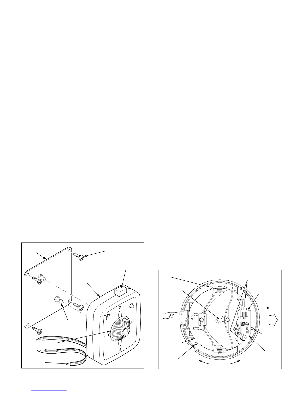
B. Snap Mounting (see figure 1).
1. Locate a suitable mounting location for the
control unit.
NOTE
Before marking the drill position marks, ensure that
the mounting plate’s orientation will allow the control
to snap on the mounting plate in the desired position.
2. Using the control mounting plate as a template, scribe four drill position marks on the mounting
surface.
CAUTION
To avoid damage when drilling, ensure that both
sides of mounting surface are clear of any parts or
wires.
Also, when drilling any holes, ensure that holes are
drilled only through sheet metal and not through
upholstery.
3. Drill four 7/64" holes at the previously scribed
drill position marks.
IV. LIGHT INSTALLATION.
A. Surface Mount Models.
To install the light, proceed as follows:
1. Push and hold the dome release button
(located in the plastic base). Turn the dome counterclockwise and lift the dome off the base (see figure 2).
2. Position the vehicle on a level surface. Select a
relatively flat mounting position which provides sufficient
rigidity to support the light and prevent vibrations caused
by the light when the vehicle is in motion.
CAUTION
Turning reflector by hand may damage motor or
worm gear. To rotate the reflector, connect to an
appropriate power source.
3. Position the light with the dome release
button toward the rear at the selected mounting location.
4. Use the base of the light as a template and
scribe three mounting hole drill position marks on the
mounting surface. Also, scribe one wire routing hole drill
position mark at the center.
CAUTION
To avoid damage when drilling, ensure that both
sides of mounting surface are clear of any parts or
wires.
Also, when drilling any holes, ensure that holes are
drilled only through sheet metal and not through
upholstery.
CONTROL
MOUNTING
PLATE
SLIDE KNOB TO MOVE
REFLECTOR POSITION
GRAY CABLE
FROM LIGHT
MOUNTING
STUDS (2)
SCREWS, #6 x 5/8", TYPE A THD. FRM.,
CONTROL
Figure 1.
PHILLIPS PAN HEAD (4)
PRESS BUTTON TO TURN
LAMP ON OR OFF
P
U
R
I
G
H
T
L
E
F
T
N
W
O
D
290A2669-03B
5. Drill one 5/8" (0.625) hole (wire routing hole)
at the previously scribed center drill position mark. Drill
three 9/64" (0.140) holes (mounting holes) at the previously
scribed outer drill position marks.
MOUNTING
-2-
HOLE
WIRING HOLE
PUSH TO
RELEASE
DOME
MECHANISM
COVER
MOUNTING
HOLE
TWIST DOME
Figure 2.
REMOVEINSTALL
RELEASE T ABS
(PUSH DOWN HERE)
CONTROL CABLE
CIRCUIT BOARD
MECHANISM
CONNECTOR
SLIDE TO
REMOVE
FRONT
MOUNTING
HOLE
PRINTED
290A2669-04B
 Loading...