

Federal Signal Corporation UltraVoice UVIC Description, Specifications, Installation, Operation, And Service Manual
Page 1
UltraVoice® Indoor Controller
Model: UVIC
Description, Specications, Installation,
255364
Rev. K3 1218
Printed in U.S.A.
© Copyright 2012-2018 Federal Signal Corporation
Operation, and Service Manual
Page 2

Limited Warranty
This product is subject to and covered by a limited warranty,
a copy of which may be found at www.fedsig.com/SSG-Warranty.
A copy of this limited warranty may also be obtained by written
request to Federal Signal Corporation, 2645 Federal Signal Drive,
University Park, IL 60484; by email to info@fedsig.com, or
by calling +1 708 534-3400.
This limited warranty is in lieu of all other warranties, express or
implied, contractual or statutory, including, but not limited to the
warranty of merchantability, warranty of tness for a particular
purpose and any warranty against failure of its essential purpose.
2645 Federal Signal Drive
University Park, Illinois 60484-3167
www.fedsig.com
Customer Support 800-548-7229 • +1 708 534-3400
Technical Support 800-524-3021 • +1 708 534-3400
All products indicated are trademarks of Federal Signal Corporation.
All other product names or trademarks are properties of their respective owners.
Page 3

Contents
Safety Messages..................................................................................................................................... 9
General Description ..............................................................................................................................11
Introduction ....................................................................................................................................................... 11
Features ............................................................................................................................................................ 11
Digital Voice Messages .....................................................................................................................................13
UVIC25ST Option .............................................................................................................................................13
UVARM Option .................................................................................................................................................. 13
UVARM Features ...................................................................................................................................... 13
UVLOC Option .................................................................................................................................................. 14
UVLOC Features ......................................................................................................................................14
Model UVIC-IP ..................................................................................................................................................14
UVIC Backplane Motherboard ..........................................................................................................................15
Commander Software System (SFCDWARE) ..................................................................................................15
Ordering Information ......................................................................................................................................... 15
Specications ....................................................................................................................................... 16
Specications for the UVIC ............................................................................................................................... 16
Specications for the UV+ Controller ................................................................................................................ 17
Specications for the UV400 Amplier ..............................................................................................................18
Specications for the UVIC Backplane Motherboard ........................................................................................ 18
Specications for the UVARM ........................................................................................................................... 19
Specications for the UVLOC ...........................................................................................................................19
Specications for the Serial to Network PCB .................................................................................................... 19
System Planning................................................................................................................................... 20
Control Unit Location ........................................................................................................................................20
Speaker Location .............................................................................................................................................. 21
UVLOC Location ............................................................................................................................................... 21
Installation ............................................................................................................................................. 21
General Mounting Guidelines For All Applications ............................................................................................ 24
UVIC Installation Material List and Installation Guidelines ................................................................................25
Concrete or Filled Cement Block Wall Mounting Guidelines ....................................................................26
Hollow Block Wall Mounting Guidelines ....................................................................................................26
Description, Specications, Installation, Operation, and Service Manual
3
Page 4

Wood Stud Wall Mounting Guidelines.......................................................................................................27
Metal Stud Wall Mounting Guidelines .......................................................................................................27
Electrical Connections ......................................................................................................................................28
DIN Rail Terminal Blocks ......................................................................................................................... 28
Wiring Guidelines for the 120 Vac Electrical Service ............................................................................... 28
Wiring Guidelines for the 240 Vac Electrical Service ............................................................................... 29
Battery Connections ..................................................................................................................................29
Installing the Antenna ........................................................................................................................................ 30
Installing the Cabinet Mounted Magnetic Base Antenna ..........................................................................30
Installing the Remote Mounted Magnetic Base Antenna ..........................................................................30
Speaker Connections ................................................................................................................................30
PA Audio Connections (JP15) ...........................................................................................................................31
Contact Closure Inputs (JP14) .......................................................................................................................... 32
Optional UVARM Connections .......................................................................................................................... 32
Optional UVLOC Connections and Wall Mounting ............................................................................................32
External 24 VDC Power Connections ............................................................................................................... 33
600 Ohm I/O Connections ................................................................................................................................34
Control Connections .................................................................................................................................34
Audio Connections .................................................................................................................................... 34
Turning on the Power ........................................................................................................................................34
Installing User-Supplied Radio Receivers ........................................................................................................36
Pre-operational System Conguration and Testing .......................................................................... 37
Visual Inspection ............................................................................................................................................... 37
Amplier and Speaker Pre-Operation Checkout ............................................................................................... 37
Adjusting the Radio Transceiver .......................................................................................................................38
Adjusting the receive audio ....................................................................................................................... 38
Adjusting the transmit deviation ................................................................................................................ 38
600 Ohm Level Adjustment Procedure for Communications ............................................................................39
600 Ohm Adjustment Procedure for External Audio Source Input .................................................................... 39
Control and Status Monitoring ..........................................................................................................................40
Testing the Optional UVLOC ............................................................................................................................. 40
Operations............................................................................................................................................. 41
UV Controller and UV400 Amplier Front Panel Indicators ..............................................................................41
Basic UVIC Controller Programming ...............................................................................................................42
UltraVoice Indoor Controller (UVIC)
4
Page 5

Unit Type ...................................................................................................................................................42
Radio Communications ..................................................................................................................................... 43
Activation Formats ....................................................................................................................................43
EAS Location Codes ................................................................................................................................. 43
128/256-bit Encryption Key ...................................................................................................................... 43
Security Key .............................................................................................................................................. 43
User Programs .................................................................................................................................................. 43
Activation Functions .................................................................................................................................. 44
Site Address Switch (S1) ..................................................................................................................................45
Connectors and Indicators for the UVARM ....................................................................................................... 47
Connectors and Indicators for the Serial to Network PCB ................................................................................ 48
Connectors for the Front Panel ................................................................................................................. 49
Connectors, Indicators, and Fuses for the Backplane Motherboard ................................................................. 50
Manual Activation .............................................................................................................................................. 54
Local Public Address ......................................................................................................................................... 54
Relay Output (JP11) .......................................................................................................................................... 55
600 ohm Input/Output (JP12) ............................................................................................................................ 55
Remote Activation (JP14) ................................................................................................................................. 55
Sensor Inputs (JP15) ........................................................................................................................................56
+5 Vdc Supply (JP16) .......................................................................................................................................57
Spare Sensor Inputs (JP17) .............................................................................................................................. 57
Two-Way Sensor Package ................................................................................................................................ 57
Local Quiet Test ................................................................................................................................................58
Operation ..................................................................................................................................................58
Finding Faults ...........................................................................................................................................58
Battery Charger ................................................................................................................................................. 58
UVLOC .............................................................................................................................................................. 59
Activating a Live PA ..................................................................................................................................59
Activating a Digital Voice Message ...........................................................................................................60
Recording a Digital Voice Message ..........................................................................................................60
Maintenance .......................................................................................................................................... 62
Control Unit Preventive Maintenance ...............................................................................................................62
General Maintenance ........................................................................................................................................ 62
Checking Signal Operational ....................................................................................................................62
Description, Specications, Installation, Operation, and Service Manual
5
Page 6

Checking the Battery .................................................................................................................................62
Replacement Parts ............................................................................................................................... 63
Getting Service ..................................................................................................................................... 64
Appendix A ICM-UV Checklist ............................................................................................................. 65
Appendix B Drawings .......................................................................................................................... 67
Tables
Table 1 Ordering UVIC .......................................................................................................................... 15
Table 2 UVIC Accessories .................................................................................................................... 15
Table 3 Ordering UVLOC and UVLOC-IM ........................................................................................... 16
Table 4 Electrical for the UVIC ............................................................................................................. 16
Table 5 Battery ...................................................................................................................................... 16
Table 6 Environmental ......................................................................................................................... 16
Table 7 Physical .................................................................................................................................... 17
Table 8 Signaling Formats ................................................................................................................... 17
Table 9 Audio Power Amplier Modules Model (UV400) ................................................................... 18
Table 10 Relay Output .......................................................................................................................... 18
Table 11 600 Ohm Balanced Line Port ................................................................................................ 18
Table 12 Remote Activation, Sensor and Direction Inputs ............................................................... 18
Table 13 Amplier Outputs .................................................................................................................. 18
Table 14 Electrical for the UVARM ...................................................................................................... 19
Table 15 Specications for the UVLOC .............................................................................................. 19
Table 16 Electrical for the Serial to Network PCB ............................................................................. 19
Table 17 Physical for the Serial to Network PCB ............................................................................... 19
Table 18 Network Port .......................................................................................................................... 19
Table 19 600 Ohm Audio Output Port for the Serial to Network PCB .............................................. 20
UltraVoice Indoor Controller (UVIC)
6
Page 7

Table 20 Bandwidth Requirements ..................................................................................................... 20
Table 21 Installer Supplied UVIC Electrical Installation Material List .............................................. 25
Table 22 Concrete or Filled Cement Block Wall Mounting Materials ............................................... 26
Table 23 Hollow Block Wall Mounting Materials ................................................................................ 26
Table 24 Wood Stud Wall Mounting Materials ................................................................................... 27
Table 25 Metal Stud Wall Mounting Materials .................................................................................... 27
Table 26 Radio Connector, 8 pin MOD jack ........................................................................................ 36
Table 27 Front Panel of UV+ Controller Card ..................................................................................... 41
Table 28 Front Panel Controls for UV+ Controller Card.................................................................... 41
Table 29 Front Panel Indicators for Model UV400 Amplier ............................................................. 41
Table 30 Unit Type Selection Table ..................................................................................................... 42
Table 31 Activation Functions ............................................................................................................. 44
Table 32 Connectors for the UVARM .................................................................................................. 47
Table 33 Indicators for the UVARM ..................................................................................................... 47
Table 34 Connectors for the Serial to Network PCB ......................................................................... 48
Table 35 Indicators for the UVIC-IP ..................................................................................................... 49
Table 36 UV+ Controller Card Setting I/O ........................................................................................... 49
Table 37 Connectors for the Backplane Motherboard ...................................................................... 50
Table 38 Fuses for the Backplane Motherboard ................................................................................ 52
Table 39 Motherboard Outline Drawing .............................................................................................. 53
Table 40 Manual Activation Switches on UV+ Controller Card ........................................................ 54
Table 41 Remote Activation Connections (JP14) .............................................................................. 56
Table 42 Sensor Connections (JP15) .................................................................................................. 56
Table 43 External Sensors ................................................................................................................... 57
Table 44 LEDs description ................................................................................................................... 59
Description, Specications, Installation, Operation, and Service Manual
7
Page 8

Table 45 Troubleshooting .................................................................................................................... 63
Figures
Figure 1 Typical UVIC Installation Drawing ........................................................................................ 22
Figure 2 UVIC Cabinet Dimensional Outline Drawing ....................................................................... 23
Figure 3 UVIC Parts Layout ................................................................................................................. 23
Figure 4 UVIC Battery Connections .................................................................................................... 25
Figure 5 UVIC25ST Wiring Detail ........................................................................................................ 31
Figure 6 UVLOC Dimensional Outline ................................................................................................ 33
Figure 7 UVLOC Interface Wiring Diagram ........................................................................................ 33
Figure 8 UVIC Strobe and Speaker Wiring ......................................................................................... 35
Figure 9 UV Controller and UV400 Amplier Front Panel Indicators .............................................. 42
Figure 10 Setting the Switch Number Example ................................................................................. 46
Figure 11 UVARM Identication .......................................................................................................... 48
Figure 12 Serial to Network Board ...................................................................................................... 49
Figure 13 UV+ Controller Card Switches ........................................................................................... 54
Figure 14 UVIC Controller Backplane Motherboard I/O .................................................................... 55
Figure 15 LEDs on charger .................................................................................................................. 59
Figure 16 Using UVLOC Controls ....................................................................................................... 60
Figure 17 UVLOC Drawing ................................................................................................................... 61
Figure 18 UVIC Wiring Diagram .......................................................................................................... 67
Figure 19 UVIC-IP Wiring Diagram ...................................................................................................... 68
Figure 20 UVIC-LL Wiring Diagram ..................................................................................................... 69
Figure 21 UVIC Final Assembly and Parts List .................................................................................. 70
UltraVoice Indoor Controller (UVIC)
8
Page 9

Safety Messages
It is important to follow all instructions shipped with this product. This device
is to be installed by trained personnel who are thoroughly familiar with the
country electric codes and will follow these guidelines as well as local codes.
Listed below are important safety instructions and precautions you should follow:
Important Notice
Federal Signal reserves the right to make changes to devices and specications detailed in
the manual at any time in order to improve reliability, function or design. The information
in this manual has been carefully checked and is believed to be accurate; however, no
responsibility is assumed for any inaccuracies.
Publications
Federal Signal recommends the following publications from the Federal Emergency
Management Agency for assistance with planning an outdoor warning system:
Safety Messages
• The “Outdoor Warning Guide” (CPG 1-17)
• “Civil Preparedness, Principles of Warning” (CPG 1-14)
• FEMA-REP-1, Appendix 3 (Nuclear Plant Guideline)
• FEMA-REP-10 (Nuclear Plant Guideline).
Planning
• If suitable warning equipment is not selected, the installation site for the siren is
not selected properly or the siren is not installed properly, it may not produce the
intended optimum audible warning. Follow Federal Emergency Management Agency
(FEMA) recommendations.
• If sirens are not activated in a timely manner when an emergency condition
exists, they cannot provide the intended audible warning. It is imperative that
knowledgeable people, who are provided with the necessary information, are
available at all times to authorize the activation of the sirens.
• When sirens are used out of doors, people indoors may not be able to hear the
warning signals. Separate warning devices or procedures may be needed to
effectively warn people indoors.
• The sound output of sirens is capable of causing permanent hearing damage. To
prevent excessive exposure, carefully plan siren placement, post warnings, and
restrict access to areas near sirens.
• Activating the sirens may not result in people taking the desired actions if those to
be warned are not properly trained about the meaning of siren sounds. Siren users
should follow FEMA recommendations and instruct those to be warned of correct
actions to be taken.
Description, Specications, Installation, Operation, and Service Manual
9
Page 10

Safety Messages
• After installation, service, or maintenance, test the siren system to conrm that it is
• If future service and operating personnel do not have these instructions to refer to,
Installation and Service
• Electrocution or severe personal injury can occur when performing various
• The sound output of sirens is capable of causing permanent hearing damage. To
operating properly. Test the system regularly to conrm that it will be operational in
an emergency.
the siren system may not provide the intended audible warning and service personnel
may be exposed to death, permanent hearing loss, or other bodily injury. File these
instructions in a safe place and refer to them periodically. Give a copy of these
instructions to new recruits and trainees. Also give a copy to anyone who is going to
service or repair the siren.
installation and service functions such as making electrical connections, drilling
holes, or lifting equipment. Therefore only experienced electricians should install
this product in accordance with national, state and any other electrical codes having
jurisdiction. Perform all work under the direction of the installation or service crew
safety foreman.
prevent excessive exposure, carefully plan siren placement, post warnings and
restrict access to areas near the sirens. Sirens may be operated from remote control
points. Whenever possible, disconnect all siren power including batteries before
working near the siren.
• After installation or service, test the siren system to conrm that it is operating
properly. Test the system regularly to conrm that it will be operational in an
emergency.
• If future service personnel do not have these warnings and all other instructions
shipped with the equipment to refer to, the siren system may not provide the intended
audible warning and service personnel may be exposed to death, permanent hearing
loss, or other bodily injury. File these instructions in a safe place and refer to them
periodically. Give a copy of these instructions to new recruits and trainees. Also, give
a copy to anyone who is going to service or repair the sirens.
Operation
Failure to understand the capabilities and limitations of your siren system could result in
permanent hearing loss, other serious injuries or death to persons too close to the sirens
when you activate them or to those you need to warn. Carefully read and thoroughly
understand all safety notices in this manual and all operations-related-items in all
instruction manuals shipped with equipment. Thoroughly discuss all contingency plans
with those responsible for warning people in your community, company, or jurisdiction.
Read and understand the information contained in this manual before
attempting to install or service the siren.
Pay careful attention to notices located on the equipment.
10
UltraVoice Indoor Controller (UVIC)
Page 11

General Description
Introduction
This manual describes the features, specications, installation, operation, and
maintenance of the UltraVoice® Indoor Controller (UVIC). The UVIC is designed
to deliver amplied audio to a network of speakers (sold separately), and congured
for indoor notication or evacuation. The UVIC has been designed for high-quality
reproduction of live or pre-recorded voice and tone that provides the ability to automate
testing and emergencies.
The UVIC is housed in a single NEMA1 style cabinet. The UVIC uses one amplier card
for a 400-Watt system and two ampliers cards for an 800-Watt system. All siren control,
audio generation, and remote communication functions are handled by a single UV+
controller board. The backplane motherboard contains connectors and terminal blocks
for interconnection of the other system components. Power is supplied by two 12-volt
batteries that are charged from the 24 Vdc battery charger.
All UVIC models are setup for two-way control and status monitoring using the
Commander® Software System (Commander) including a nominal 12 V radio power
supply and antenna lightning protector. All models can be equipped with a micro memory
SD card to store up to 17 hours of tone or digital voice messages. Custom digital voice
recording requires a model DVR.
General Description
Features
Activation codes, command sequences, and operating parameters are uploaded from a
computer through the RS232 port located on the front panel or over the radio channel
with Commander. All user information is stored in non-volatile FLASH memory, immune
to power and battery failure.
The UVIC can be activated by landline, radio or IP from a remote location. Landline
activation can initiate one of the eight on-board functions by connecting a momentary
dry contact closure (customer supplied) to the appropriate PC board mounted terminal
block. These functions can contain a combination of tone and prerecorded voice or Public
Address. Public Address is available from the supplied microphone located inside the
controller.
The UVIC controller has the following features.
• Seven standard warning signals: wail, alternate wail, pulsed wail, steady, alternate
steady, pulsed steady, and Westminster chime (auxiliary).
• Optional micro SD card for custom message storage. Store up to 4,093 voice or tone
messages that total up to 17 hours of total recording time.
• Use local pushbuttons (eight) on controller card for testing or local siren activation.
• Ability to interface with up to eight externally wired pushbuttons for siren activation.
• Local microphone for live public address (PA) with internal mount.
• Single tone, Two-tone, DTMF, EAS and MSK decoders for remote siren control.
Description, Specications, Installation, Operation, and Service Manual
11
Page 12

General Description
• Relays for local activation of strobes, LEDs, and legacy rotation siren designs.
• Siren activation verication through specialized Quiet Test.
• Ability to select or group ampliers to create exible zones.
• Volume control per message to optimize siren notication.
• Modular hot swappable design to easily service cards without shutting off the power.
• Ability to stack multiple voice and tone alerts to create custom messages.
• Status system monitoring for system health and readiness.
• Flexible communications—radio (analog, P25, trunking, digital, broadband),
satellites, cellular, landline, and IP)
• Cellular and satellite communication options are available upon request. Contact your
local Federal Signal sales representative for more information.
• Ability to mix various communication formats for high-system availability and
redundancy.
• Secure communication with 128-bit or 256-bit encryption.
• Secure activation programming and status monitoring through the SS2000+ and
Commander Software System.
• UVARM has the ability to send line level audio output to external equipment such as
re alarm panels or ampliers, and relays for activation of strobes or LEDs.
• Power control ramps up siren or speaker volume for added safety, custom volume
settings, and low power testing.
Cabinet Features
• Single NEMA1/UL type 1, powder coated steel cabinet
• Single lockable door hasp that can be easily opened without tools
• Wall mountable
• 8 multi-size knockouts for conduit entrances
• Bulkhead mounted type N female antenna connection
Ampliers (Model UV400) Features
• Two amplier slots for 400 watt ampliers, with audio output of 70 V
RMS
12
• Optionally, one UV400 with a UVIC25ST (25 V
step-down transformer)
RMS
• 12 speaker pair connections per amplier
Batteries
• 44 A/H, sealed VRLA AGM type (included)
• Over 45 minutes full sounding battery backup without AC power
UltraVoice Indoor Controller (UVIC)
Page 13

Battery Charger (UVIC charger was updated Jan 2017)
• 24 Vdc, 5 A
• Temperature compensated
• Selectable oat voltage 13.2-13.8 Vdc
Digital Voice Messages
When purchased, the Digital Voice option adds a micro SD card that is capable of storing
up to 17 hours or 4,093 pre-recorded messages.
The digital voice message format is 8 kHz sample rate, 8 bit mono.
UVIC25ST Option
When purchased, the UVIC25ST allows the end user the capability to reduce audio
voltage output from the 70 V
UVARM Option
The UltraVoice Audio and Relay Output Module (UVARM) provides three separate
audio outputs for the UVIC controller to interface with other devices and systems.
The outputs consist of a balanced 33 ohm, a balanced 600 ohm, a selectable 600 ohm
balanced or single-ended line level output and four SPDT relay outputs. The level of each
audio output is independently adjustable. Each audio and relay output is individually
addressable allowing each output to be activated at different times.
standard to the 25 V
RMS
standard.
RMS
General Description
The UVARM connects to one of the two control card connectors on the UVIC
motherboard and is mounted on an aluminum faceplate with mounting holes for attaching
to the UVIC card cage. The connectors for the UVARM are located on the front of the
card and extend through openings in the faceplate. Use Commander to assign Audio and
Relay outputs to functions. Audio and Relay outputs may be selectively programmed to
be active together or individually with any control function. Program the outputs to stay
on for the duration of the function, or latch on until turned off.
UVARM Features
The UVARM has the following features.
• Balanced 33 ohm output
• Balanced 600 ohm output
• Selectable balanced or single ended 600-ohm line level output
• Four SPDT relay outputs
Description, Specications, Installation, Operation, and Service Manual
13
Page 14

General Description
UVLOC Option
The UltraVoice Local Operating Console (UVLOC) is an activation point for the
UltraVoice controller series.
The UVLOC offers the capability to do the following:
• Activate seven tone or pre-recorded digital voice messages
• Record/play a live voice message
• Conduct live public address (PA) announcements
The UVLOC is ideal for providing multiple activation points in an Indoor Mass
Notication System. The UVLOC is rated for indoor use and can be surface or recessed
mounted. Six UVLOCs can be interfaced into an UVIC controller, as each UVLOC is
hard-wired using standard CAT5 cable and battery operated from its respective UVIC
controller. The UVLOC may be located up to 1/2 mile away from the UVIC controller
and requires no local power source of its own.
The UVLOC interface board includes six RJ45 connections to connect to individual
UVLOC units. The UVLOC interface board also includes a connection to interface to a
second additional UVLOC interface board (optional).
Outtted with onboard LEDs, the UVLOC indicates when the unit is armed and powered.
In addition, arming the UVLOC signals the Commander Software System, alerting
operators that the unit has been activated for use.
UVLOC Features
The UVLOC has the following features.
• Operator interface panel for controlling 7 digital messages, live P.A., record and
• Remotely powered from the UVIC controller
• LED status indicators
• Balanced 600 ohm output
• CAT5 wiring interface
• Battery operation
• On-board noise canceling microphone
• LED lights up when armed
playback functions, and two auxiliary user programmable functions.
14
Model UVIC-IP
The UVIC-IP includes a network card that provides the capability to communicate over a
network and provides audio decoding of digitized audio sent over the network.
The network card is congured with its own xed IP address and port number. When
packets of data are received over the network port that are addressed to the board’s IP and
port number, they are converted to serial data and sent out over the serial port. Likewise,
UltraVoice Indoor Controller (UVIC)
Page 15
any data coming into the serial port is converted to TCP/IP data packets and sent out
over the network port to the server’s IP address. The unit also contains a digital to analog
converter. This allows specially congured incoming data packets to be converted to
audio, which is then ltered and sent out over a 600-ohm audio port.
UVIC Backplane Motherboard
The UVIC backplane motherboard provides the electrical connections between the UV+
Control board, the Audio and Relay output board, and the UV400 ampliers. In addition,
it provides connections for eld wiring and relay outputs.
The UVIC backplane motherboard is limited to two amplier slots or one amplier if
used with the UVIC25ST.
The UVIC backplane motherboard has a fused normally open relay output. The relay is
normally programmed to close while a control function is active. An LED indicator turns
on when the relay is active.
Commander Software System (SFCDWARE)
Commander is software used to control, monitor, and congure the siren controller. The
programming software communicates with the siren controller over the communication
link. Refer to the Help menu provided with the software for operational details.
General Description
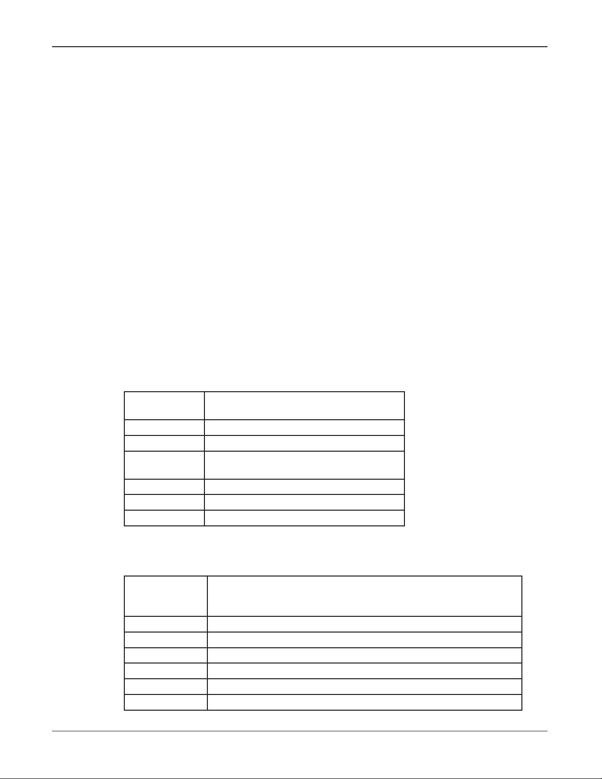
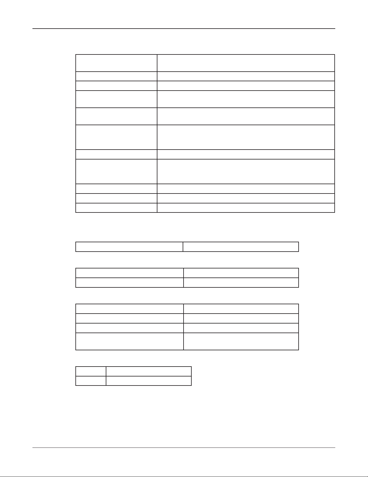
Ordering Information
Table 1 Ordering UVIC
UVIC Model/
Part Numbers
UVIC No Radio (RF), 120 V
UVICH Two-way VHF (134-174 MHz)
UVICU Two-way UHF (400-470 MHz)
UVIC-IP IP-enabled
UVIC-LL Landline
UVIC240 UVIC with 240 Vac transformer, No Radio
*
Requires IP Networking Software
Table 2 UVIC Accessories
UVIC
Accessories/
Part Numbers
DVSD Digital voice mini SD card: 4,093 messages, 17 hours
DVR Digital voice recording fee per 16 messages
UV400 400-watt Amplier
SFCD* Commander Software System,*10, 25, 255, or 512 Site License
TB-LL Telco base, landline communication interface
UVARM UltraVoice Audio Relay Module
Description
(450-512 MHz, optional)
*
Description
Description, Specications, Installation, Operation, and Service Manual
15
Page 16
Specications
UVIC
Accessories/
Part Numbers
UVIC25ST Step-down transformer, 70-25 V
ENWSSPA Wall-mounted speaker strobe
ENWSTPA Wall-mounted strobe
ENCSTA Ceiling-mounted strobe
DSA1 100-watt speaker
Description
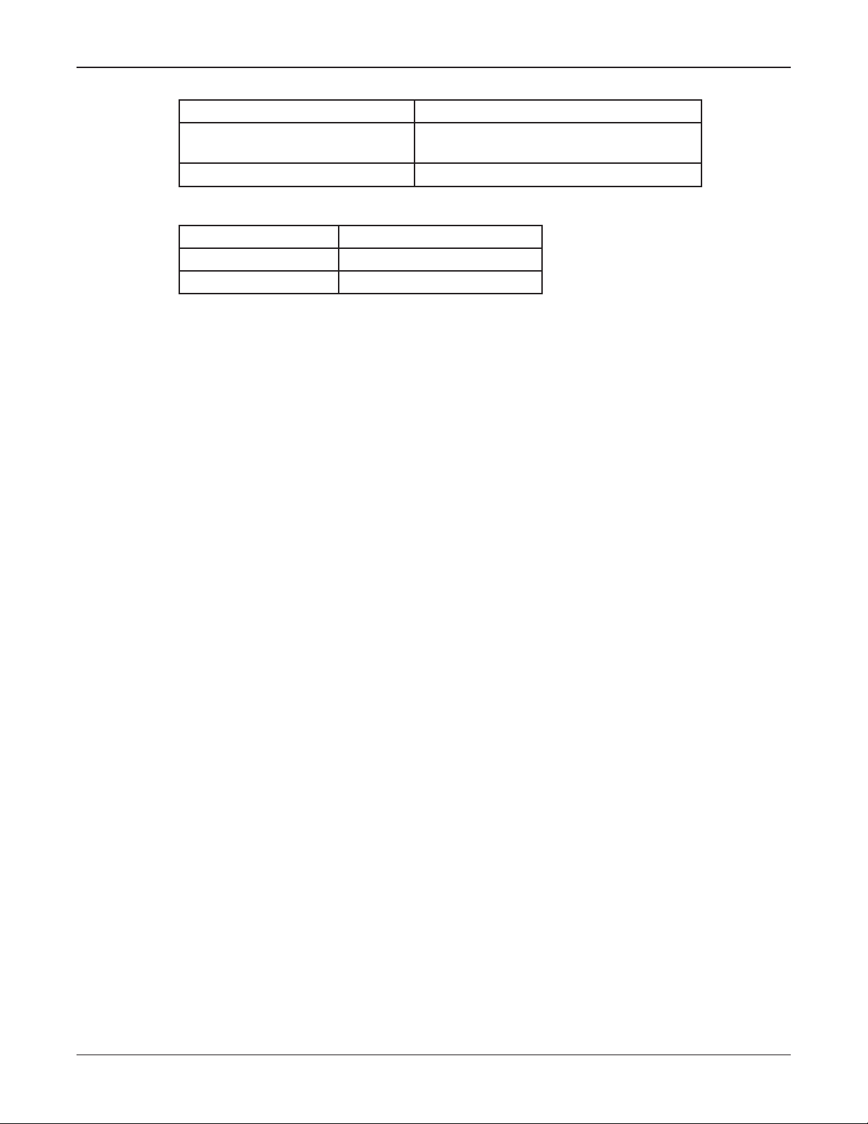
Table 3 Ordering UVLOC and UVLOC-IM
UVLOC
Part Numbers
UVLOC Maximum of (10) units can be interfaced to a UltraVoice Siren
UVLOC-IM One (1) Interface module must be ordered per UV or UVIC
Description
Controller (UV) or UltraVoice Indoor Controller (UVIC)
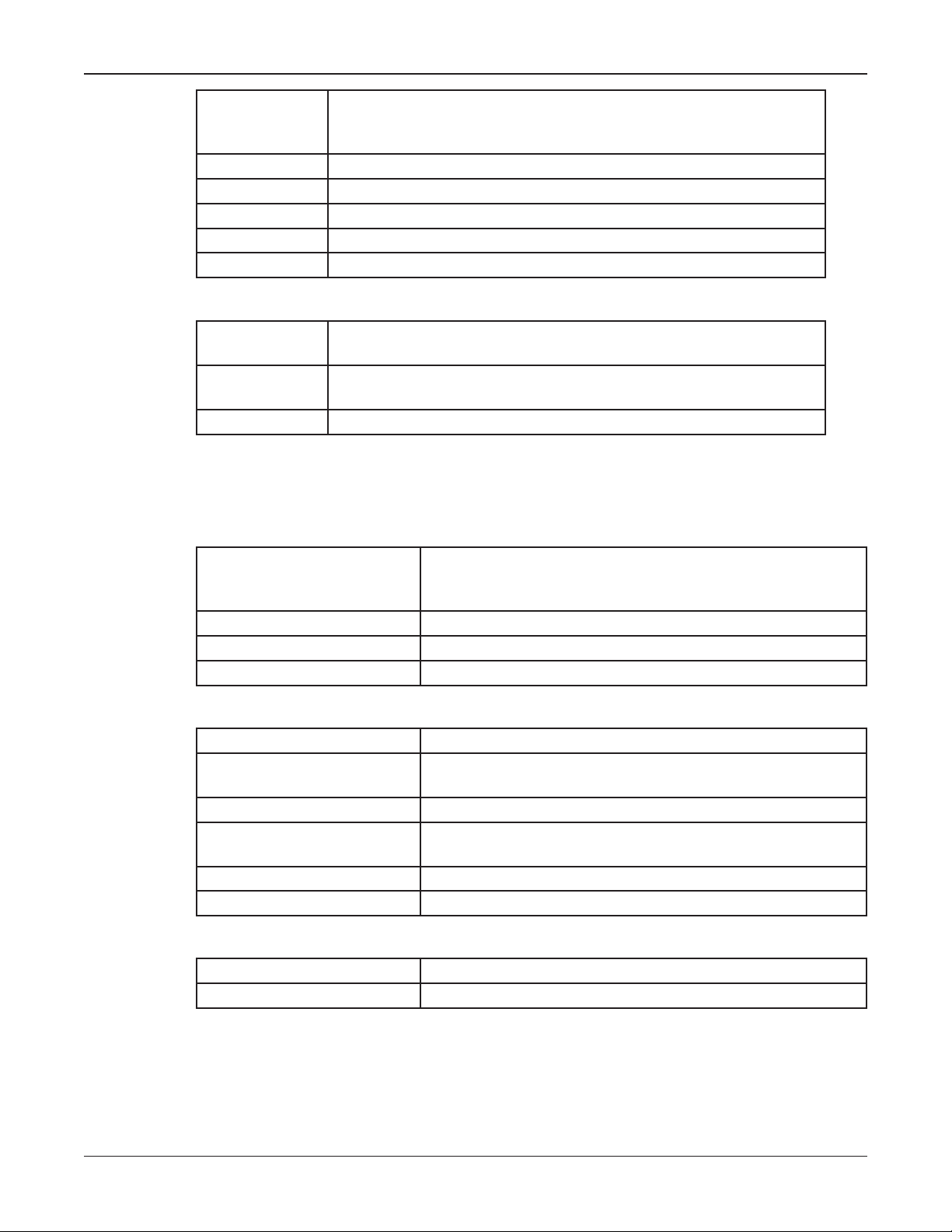
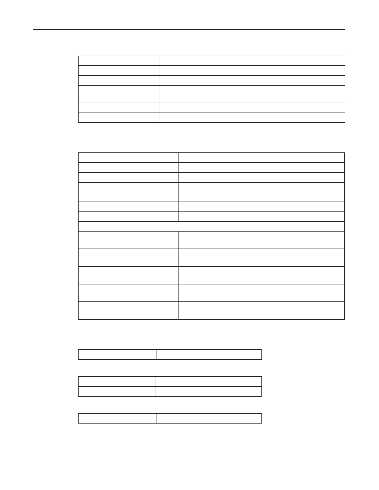
Specications
Specications for the UVIC
Table 4 Electrical for the UVIC
AC Input Voltage 120 or 240 Vac (UVIC240) +/- 10%
AC Input Current 5 amps AC
Operating Voltage 24 Vdc
Continuous Signaling Time 30 minutes
(UV25ST with custom cable)
rms
50-60 Hz* Single-phase
(*two separate models)
Table 5 Battery
Battery Input Voltage 20-28 Vdc, 27 Volts
Battery Current 120 mA standby current, up to 22 A for each amplier
module running, 50 amps
Battery Capacity > 45 minutes continuous operation without AC power
Standby Time > 72 hours (3 days) including two-way radio
(with 5-minute full signal reserve minimum)
Type VRLA
Rating 44 A/H minimum
Table 6 Environmental
Operating Temperature -22°F to 149°F/-30°C to +65°C
Humidity 0-98% non-condensing
NOTE
• The UVIC can operate throughout this temperature range provided the battery
temperature is maintained at -18°C/-0.4°F or higher.
• The UVIC housing carries a NEMA 1 rating.
16
UltraVoice Indoor Controller (UVIC)
Page 17
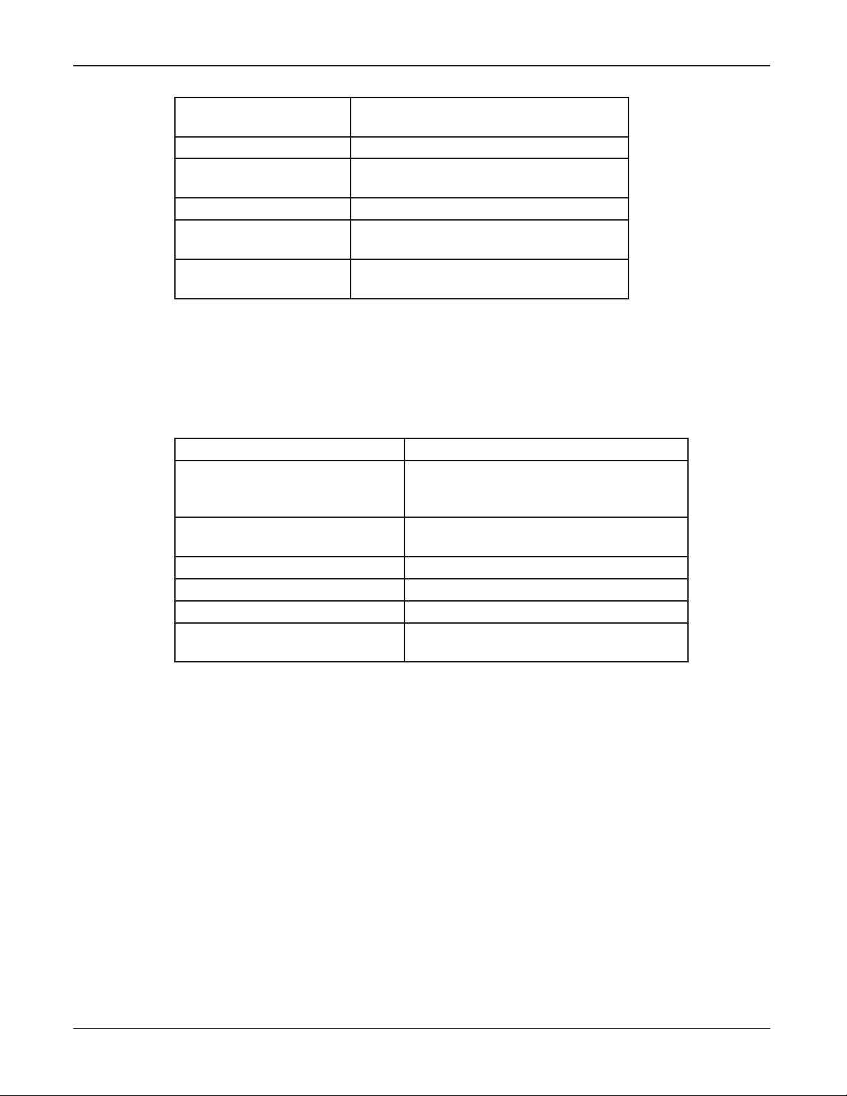
Table 7 Physical
UV400 ampliers
(H x W x D)
UV400 ampliers Weight 4.12 lb/1.9 kg
Control cabinet
(H x W x D)
Weight (no ampliers) 65.55 lb/ 29.28 kg
Weight
(including batteries)
Shipping Weight
(including batteries)
10.5 x 2.0 x 8.5 inches
26.7 x 5.1 x 21.6 cm
31 x 17.36 x 13.62 inches
78.73 x 44.09 x 35.59 cm
130 lb/ 58.97 kg
200 lb/ 90.72 kg
Refer to Federal Signal Website (http://www.fedsig.com/) for current recommended
batteries. Use of batteries other than those specied may degrade the operation of this
product and void the warranty.
Specications for the UV+ Controller
Table 8 Signaling Formats
Number of codes Up to 50 activation codes maximum
Two-Tone Sequential or Single
Tone
DTMF 3 to 12 digits standard
AFSK 1200,N,8,1 (MSK two-way modem)
EAS AFSK, 520.83 baud
Modem Tones 2083.3 Hz and 1562.5 Hz
Number of functions allowed
stacked under each code
Specications
282-3000 Hz
0.5 (A) - .25 seconds (B) minimum to
8 seconds maximum
50 ms/50 ms timing or greater
Up to 20
Description, Specications, Installation, Operation, and Service Manual
17
Page 18
Specications
Specications for the UV400 Amplier
Table 9 Audio Power Amplier Modules Model (UV400)
Input Voltage 24 Vdc nominal
28 Vdc maximum
Input Current Siren mode At 24 Vdc with 1 kc square-wave into 11 ohms: < 20 A
Input Current Voice Mode At 24 Vdc with 1 kHz tone set to 67 V
Standby current ampliers
turned off
Efciency > 90% – siren mode
Output Voltage into 11
ohms at 1 KHz and 24 Vdc
nominal operating voltage
Input impedance 100 K ohms
Duty Cycle,
Continuous Signaling
Times
Audio distortion < 10% – voice mode – below clipping
Frequency response +/- 3 dB, 300-3000 Hz
Power Low Power mode < 5 W per amplier
< 10 mA
> 80% – voice mode
67 V
RMS
67 V
RMS
Siren Mode 30 minutes
Digital Voice or PA 30 minutes (depending on signal
source)
minimum – siren mode
minimum – voice mode
into 11 ohms: < 24 A
RMS
Specications for the UVIC Backplane Motherboard
Table 10 Relay Output
Contact Rating 30 Vdc, 15 A
Table 11 600 Ohm Balanced Line Port
Audio Input Level 0.10 to 2 V
Audio Output Level 0.25 to 2.0 V
Table 12 Remote Activation, Sensor and Direction Inputs
Number of Remote Activation Inputs 8
Number of Remote Sensor Inputs 4
Number of Direction Sense Inputs 4
Input Type Optically isolated activated by dry
contact closure < 2 k ohms
Table 13 Amplier Outputs
Number 12 speaker connection/amp
Rating 22-14 AWG
to make 1 V
P-P
P-P
TP10
P-P
18
UltraVoice Indoor Controller (UVIC)
Page 19
Specications for the UVARM
Table 14 Electrical for the UVARM
Current Draw < 200 mA
Balanced 33 ohm output Adjustable from 0.2-1.9 V
Balanced 600 ohm output Adjustable from 0.2-3 V
Single-ended or balanced
Line-level/600 ohm output
Relay outputs 4 SPDT
Contact rating 20 A at 30 Vdc with NO and NC contacts
Specications for the UVLOC
Table 15 Specications for the UVLOC
UVLOC Operating Voltage 20-32 V dc
Current Draw < 25 mA
UVLOC Interface Module 20-32 V dc
Operating Current < 50 mA
ARM Input 0-5 Vdc, 5 Vdc = ARMed
ARM Output 7.4-8.0 Vdc Not ARMed, 20-32 Vdc ARMed
Audio Output 600 ohm balanced, adjustable 700 mV
Installation Specications
Maximum distance between
UVLOC and UV Controller
Maximum Number of UVLOCs
per UV Controller
UV Control Panel
Interface Cable
Operating Temperature Indoor use, non condensing humidity
Size (H x W x D) 10 x 4.75 x 3 inches maximum
Specications
RMS
or -12 to +11 dB, surge protected
RMS
Adjustable from 0.2-3 V
Approximately half mile of cable, </=200 ohms of cable
6 (unless optional card is ordered)
External wire management required
CAT5, 4 pairs
-22°F to 149°F/-30°C to 65°C
25.4 x 12.1 x 7.6 cm
RMS
P-P
to 5 V
P-P
Specications for the Serial to Network PCB
Table 16 Electrical for the Serial to Network PCB
Current Draw < 150 mA
Table 17 Physical for the Serial to Network PCB
Dimensions (H x W x D) ~ 2 in x 4 in x 6.5 in
Weight < 2 lb
Table 18 Network Port
Protocol IEEE 802.3, 10 Base-T connection
Description, Specications, Installation, Operation, and Service Manual
19
Page 20
System Planning
Table 19 600 Ohm Audio Output Port for the Serial to Network PCB
Impedance 600 ohms
Audio Output Level
(-17 to +2.7 dB) into 600 ohms
R1 600 ohm audio output level set
Table 20 Bandwidth Requirements
Voice Over IP 150 K baud per connection
Siren Activation 50 bytes per connection
Siren Poll Response 74 bytes per connection
System Planning
Control Unit Location
The information in this section provides the user with guidelines necessary for
installation.
Consider the Control Unit mounting location. Mount the Control Unit NEMA Type 1
cabinet indoors and away from moisture, heavy dust, and contaminants. The controller
contains batteries; therefore, the selected area must have adequate ventilation to prevent
accumulation of explosive gas from the batteries.
Adjustable from 0.30 to 3.00 V
using R1
p-p
A light duty lockable hasp secures entry to the cabinet.
The cabinet is suitable for wall mounting with mounting slots on 12 to 16 inches centers.
The total weight of the control assembly, including user-provided batteries, are listed
in the specication section. Ensure that the mounting surface and fasteners can safely
sustain the weight of the assembly.
The control system requires a 120 Vac or 240 Vac, 50 to 60 Hz power source (model
dependent).
You can use several methods to activate the UVIC system. Use the manual activation
switches and a handheld microphone to activate the system locally. Use landline control
through normally open contact switches. Make connections directly to the backplane
motherboard terminal block. The system can be remotely activated through a radio
transceiver or an external 600-ohm audio source.
If you are using radio control, consider RF coverage and antenna placement when
selecting a suitable location.
20
UltraVoice Indoor Controller (UVIC)
Page 21

Speaker Location
The sound output of speakers is capable of causing permanent hearing
damage. Ensure people are not exposed to sounds exceeding 120 dB. Post
warnings where applicable.
As a general rule, the warning signal SPL should be at least 10 dB above the ambient
sound level to ensure it will be heard. Speaker delity and placement will also affect
voice intelligibility.
Many factors affect the propagation of sound through barriers, over various types of
materials, terrain, and changing weather conditions. Consult FEMA CPG1-17, CPG1-14
and your local Federal Signal representative for assistance to properly place your warning
equipment.
Selectively turn on the speakers connected to the UVIC using amplier zones. Program
up to two zones into the UVIC to allow Zone 1, Zone 2, or all amp zones to be activated.
Program Amp Zones using the AZ commands in Commander.
Installation
UVLOC Location
Mount the UVLOC in an area that is readily accessible by all potential operators. Clearly
mark the console to identify its location.
Connect up to 6 Local Operation Consoles to each UVIC. Place the consoles up to
1/2 mile away from the UVIC. Wall mount the console approximately 5 feet above the
ground. Mount the UVLOC as far as possible from the speaker locations to reduce the
potential for audio feedback during a live P.A.
The UVLOC requires a CAT5 cable run between the UVIC and the UVLOC. An
electrical back box is provided for mounting the UVLOC either on or recessed within
a wall. Six RJ45 connectors are provided on the UVLOC interface board for making
connections. A terminal strip is also provided that accepts bare wire.
Installation
Electrocution or severe personal injury can occur when making electrical
connections, drilling holes, or lifting equipment. Therefore, experienced
electricians in accordance with national and local electrical codes, acting
under the direction of the installation crew safety foreman, should perform
installation.
Explosive gases and corrosive materials may be present. To prevent explosion
or severe personal injury, installation technicians must be experienced with
the safe installation of lead-acid type batteries.
Description, Specications, Installation, Operation, and Service Manual
21
Page 22

Installation
Fused AC
Service
Disconnect
Distributed Speakers
Antenna Ground Required
For Outdoor Antenna Masts
120 or 240 VAC Service
(Depending on UVIC Model)
(22-14 AWG COPPER, 4mm
2
max)
Audio Wire Pairs
14-12AWG COPPER
AC Power Wires
UVIC
Radio Antenna
Field Ground
3/8" Ground Stud
Type N RF Connector
Field Ground
The output level of high-powered speakers is capable of causing permanent
hearing damage. To prevent excessive exposure, carefully plan placement
of siren and post warnings. To prevent excessive exposure to installers and
service personnel, adequate measures must be taken to ensure that the sirens
are not activated while they are within 150 feet of the speaker array or provide
proper ear protection.
Figure 1 Typical UVIC Installation Drawing
22
UltraVoice Indoor Controller (UVIC)
Page 23

Figure 2 UVIC Cabinet Dimensional Outline Drawing
Installation
Figure 3 UVIC Parts Layout
Description, Specications, Installation, Operation, and Service Manual
23
Page 24

Installation
General Mounting Guidelines For All Applications
These general installation instructions are pertinent to all installations. Specic mounting
methods and required installation materials are described in the next section.
1. There are three pre-drilled holes in each of the cabinet mounting anges. (See
Figure 3 UVIC Cabinet Dimensional Outline Drawing.) Depending on the mounting
surface, mount the cabinet using either of the following sets of holes:
• (2) Centered 0.41 inch diameter mounting holes
• (4) Mounting slots 0.41 by 2 inches with 12 to 16 inches centers
2. The total weight of the UVIC cabinet with batteries is listed in the Specications
section. It is imperative that the mounting surface and mounting method selected can
safely sustain the weight of the assembly. To reduce the weight of the cabinet during
installation, do not install the batteries before mounting the cabinet.
3. Prepare the mounting surface for hanging the cabinet by predetermining the location
of the mounting holes. Attach the cabinet to a wall or other substantial vertical
surface using the four 0.41 inch mounting slots. Alternatively, use the two center
mounting holes alone, if securely lagged directly into a wood stud or other vertical
surface capable of handling the weight load.
If the mounting surface is not at, the cabinet may require shimming to keep the
cabinet square.
4. Guidelines for various attachment methods to accommodate different wall types are
described in the following section. Make provisions for spacing behind the cabinet
when mounting to an exterior wall that is susceptible to condensation or other surface
moisture.
5. With the two batteries removed, use two people to lift the cabinet to the desired
mounting height and lag to the wall using the prepared holes and anchors.
24
UltraVoice Indoor Controller (UVIC)
Page 25

Installation
6. After the cabinet is securely mounted, remove any debris that may have entered the
cabinet. Remove the two battery hold-down brackets on the bottom right side of the
enclosure. Install the batteries oriented as shown in Figure 5, but do not connect any
wires to the batteries. Re-install the battery hold-down brackets over the batteries.
Figure 4 UVIC Battery Connections
CHGR
CHGR
7. If the UVIC model being installed has a two-way radio, ensure the radio power
switch is turned off until all wiring is completed to avoid damaging the radio.
UVIC Installation Material List and Installation Guidelines
The following material lists and guidelines describe basic installation details required to
install the UVIC cabinet. This list varies depending on mounting methods, other options,
local and national electrical codes. Use lists as a reference guide only.
Table 21 Installer Supplied UVIC Electrical Installation Material List
Material Description Purpose Qty
30 amp/250V/ 2 Pole Solid Neutral/
Fused Disconnect with Ground Kit/
NEMA 1 Rating/ Lockable Cover
Tang/ Lockable Operator
15 A FRNR Fuse Fuses for 120 V Service 1
10 A FRNR Fuse Fuses for 240 V Service 2
12-14 AWG White Wire AC Neutral from disconnect 8 ft
12-14 AWG Black Wire AC Load from disconnect 8 ft
12-14 AWG Green Wire Equipment ground from disconnect 8 ft
Optional Electrical Disconnect 1
Description, Specications, Installation, Operation, and Service Manual
25
Page 26

Installation
Material Description Purpose Qty
1/2 inch Seal Tight Conduit and
Fittings
Metal Ground Bushings Equipment ground connections 2
Screws, appropriate to mounting
surface
15 A Breaker Service panel breaker serving unit 1
White Wire appropriately sized AC neutral from breaker panel to disconnect Varies
Black Wire appropriately sized AC load from breaker panel to disconnect Varies
Green Wire appropriately sized Equipment ground from breaker panel to
Conduit and ttings, appropriately
type and size for particular
installation requirements
#6 Stranded Cabinet ground to earth ground for external
Electrical conduit from disconnect 5 in
Disconnect mounting 4
disconnect
Electrical conduit from breaker panel to
disconnect
antenna applications
Concrete or Filled Cement Block Wall Mounting Guidelines
Varies
Varies
Varies
Table 22 Concrete or Filled Cement Block Wall Mounting Materials
Material Description Purpose Qty
3/8 x 3 in
Pin/Sleeve/Lock Washer/Nut
Style Anchors
1. Mark the mounting hole locations on the wall for the cabinet.
2. Install the anchor bolts for the four cabinet corners according to the manufacturer’s
instructions.
3. Mount the cabinet to the wall.
4. Proceed to following section.
NOTE: If wall is not straight, use shims to insure enclosure maintains square and
structural integrity.
Hollow Block Wall Mounting Guidelines
Table 23 Hollow Block Wall Mounting Materials
Material Description Purpose Qty
3/8 x 4 in Heavy Duty Toggle Bolts Anchor Bolts 4
Anchor Bolts 4
26
1. Mark the mounting hole locations on the wall for the cabinet.
2. Install the anchor bolts for the four cabinet corners according to the manufacturer’s
instructions.
3. Mount the cabinet to the wall.
4. Proceed to following section.
UltraVoice Indoor Controller (UVIC)
Page 27

Wood Stud Wall Mounting Guidelines
Table 24 Wood Stud Wall Mounting Materials
Material Description Purpose Qty
3/8 x 3 in Lag bolts Backboard and cabinet mounting bolts 8
24 x 36 x 3/4 in
B/C or better plywood
Construction adhesive Mounting backboard attachment 1
1. Locate the wall studs for attaching the mounting backboard to the wall. Attach the
backboard to at least two studs.
2. Mark the wall stud location on the mounting backboard and drill four pilot holes for
the 3/8-inch lag bolts.
3. Apply construction adhesive to the back of the mounting backboard.
4. Attach the mounting backboard to the wall with four 3/8 by 3 inch lag bolts.
5. Locate the mounting position of the cabinet on the mounting backboard.
6. Drill pilot holes for the 3/8 by 3 inch lag bolts.
Installation
Mounting backboard 1
7. Mount the cabinet to the mounting backboard.
8. Proceed to the following section.
Metal Stud Wall Mounting Guidelines
Table 25 Metal Stud Wall Mounting Materials
Material Description Purpose Qty
3/8 x 3 in Lag bolts Cabinet mounting bolts 4
24 x 32 x 3/4 in
B/C or better plywood
#10 x 3 inch metal stud screws Backboard mounting 12
Construction adhesive Backboard mounting 1
1. Locate the wall studs for attaching the Mounting Backboard to the wall.
2. Mark the wall stud location on the mounting backboard and drill pilot holes for the
#10 by 3 inch metal stud screws. Place six screws in each stud evenly spaced apart.
3. Apply construction adhesive to the back of the mounting backboard.
4. Attach the mounting backboard to the wall with #10 by 3 inch metal stud screws.
5. Locate the mounting position of the cabinet on the mounting backboard.
Mounting backboard 1
6. Drill pilot holes for the 3/8 by 3 inch lag bolts.
7. Mount the cabinet to the mounting backboard.
8. Proceed to the following section.
Description, Specications, Installation, Operation, and Service Manual
27
Page 28

Installation
Electrical Connections
Install the siren electrical system in compliance with local electrical codes
and NEC recommendations. Federal Signal recommends that all user-installed
conduit connections enter from the bottom of the UVIC cabinet using the
supplied conduit knockouts. Disconnect all power and read all warnings at the
beginning of this manual and on the batteries before making connections.
The UVIC cabinet must be properly connected to an earth ground. The
cabinet contains an external 3/8 inch ground stud for making this connection.
Alternatively, a DIN mounted grounding block is provided inside the UVIC
enclosure.
If an outdoor antenna is used, install a separate antenna ground.
Externally installed antennas require a dedicated ground to either a ground
rod or building steel below grade in addition to the UVIC cabinet ground.
Verify the AC voltage requirement for the UVIC model being installed. 240 Vac
versions of the UVIC controllers have a “240” sufx in the model number
shown on the label located on the cabinet door. All other UVIC models are to
be wired to 120 VAC.
DIN Rail Terminal Blocks
These points provide a convenient location for making electrical connections. Push a
small screwdriver into the square opening in the terminal block to open the contact of the
block. With the wire inserted, the block clamps the wire with a spring-loaded connection
when the screwdriver is removed from the terminal block.
Each terminal block accepts bare 12-14 AWG wire. The two fused terminal blocks
labeled F1 and F2 have a built-in disconnect that ips open, disconnects the circuit, and
provides access to the fuse located inside the terminal block.
Wiring Guidelines for the 120 Vac Electrical Service
To wire for the 120 Vac electrical service:
1. Install a dedicated 15 A circuit breaker in an existing breaker panel or install a new
breaker panel if necessary for the UVIC.
2. Install conduit from the breaker panel to a conduit entrance in the bottom of the
UVIC.
28
3. Route user-supplied 12-14 AWG wires (1 black, 1 white, 1 green - optional) through
the conduit from the UVIC cabinet and the fused breaker panel.
4. Connect the white neutral wire from the breaker panel neutral to the fused DIN rail
mounted terminal block labeled F1-NEUTRAL in the UVIC cabinet.
UltraVoice Indoor Controller (UVIC)
Page 29

5. Connect the black line wire from the 15 A breaker to the DIN rail mounted terminal
block labeled F2-Line in the UVIC cabinet.
6. Optionally, connect a green ground wire from the breaker panel earth ground to the
green ground block in the UVIC cabinet or run a ground lead from the external 3/8
inch ground stud on the UVIC cabinet to earth ground.
7. To avoid shorting the output of the charger, do not apply AC power to the UVIC
controller before making the battery connections described later in this section.
Wiring Guidelines for the 240 Vac Electrical Service
To wire for the 240 Vac electrical service:
1. Install a dedicated 15 A 2-pole circuit breaker in an existing breaker panel or install a
new breaker panel if necessary for the UVIC.
2. Install conduit from the beaker panel to a conduit entrance in the bottom of the
UVIC. Ensure the conduit is adequately grounded.
3. Route user-supplied 12-14 AWG wires (2 black, 1 green - optional) through the
conduit from the UVIC cabinet and the fused breaker panel (or as otherwise specied
by code).
Installation
4. Connect one line wire from the 15 A breaker panel to the fused DIN rail mounted
terminal block labeled F1--L1 in the UVIC cabinet.
5. Connect the other line wire from the 15 A breaker to the DIN rail mounted terminal
block labeled F2--L2 in the UVIC cabinet.
6. Optionally, connect a green ground wire from the breaker panel earth ground to
the green ground block in the UVIC cabinet or run a ground lead from the external
3/8 inch ground stud on the UVIC cabinet to earth ground.
7. To avoid shorting the output of the charger, do not apply AC power to the UVIC
controller before making the battery connections described later in this section.
Battery Connections
When installing or removing batteries, take care to avoid shorting battery
terminals to metal surfaces. Failure to do so could result in serious personal
injury or death. Batteries miswired can cause serious personal injury or
death. Read and understand the following information before making actual
connections.
To connect the battery:
1. The battery disconnect plug is located behind the cover plate on the right side of the
ampliers. Disconnect the battery cable from the motherboard by grasping the black
connector with the large 8 AWG red and black wires and unplugging it from the
motherboard.
Description, Specications, Installation, Operation, and Service Manual
29
Page 30

Installation
2. Open the fastener kit provided in the UVIC cabinet containing the plastic battery
terminal knobs and spacer nuts. Replace the battery terminal bolts provided with the
battery with the terminal knobs and nuts provided in the fastener kit. The kit also
contains rubber bumpers that are placed under the battery holding brackets to better
secure shorter batteries.
3. Connect the wires to the batteries connecting the short black 8 AWG wire between
batteries 1 and 2 last. Use an anti-oxidant compound to protect the terminals.
4. Verify the battery connections are tightened securely to make proper electrical
connections.
Installing the Antenna
Determine type of antenna to be installed:
• Cabinet Mounted Magnetic Base
• Remote Mounted Magnetic Base
• Yagi external antenna type
• Omni external antenna type
For installation instructions on the Yagi and Omni Antennas go to the Federal Signal’s
website.
Installing the Cabinet Mounted Magnetic Base Antenna
If the UVIC is being installed in a very good RF coverage area, you may use a cabinet
Mounted Magnetic Base antenna.
1. Connect the antenna cable to the antenna connector on the top of the UVIC cabinet.
2. Mount the magnetic antenna base on the top of the UVIC cabinet.
Installing the Remote Mounted Magnetic Base Antenna
The Remote Magnetic Base antenna allows for additional antenna height to improve
reception.
1. Locate a suitable location for the antenna that is away from any electrical devices,
high voltage and computer wiring. Locate as high as possible to enable the antenna
mast to be at least 2 feet away from any grounded metal objects.
2. Mount the antenna to a at, secure metal structure with at least 225 square inches
(1.5 square foot area) that the Magnetic Mount will securely stick to.
Speaker Connections
The speaker connections are located on the bottom right hand side of the motherboard.
There are two 12 position removable connectors for each of the ampliers enabling up to
12 pairs of wires to be connected to each amplier.
30
The connectors for Amplier 1 are located under the card cage. The connectors for
Amplier 2 are located under the cover plate immediately to the right of the ampliers.
UltraVoice Indoor Controller (UVIC)
Page 31

Installation
The output voltage is 70 V
for each of the ampliers. You may connect up to 400 watts
RMS
of speaker loads across the 70 V line for each amplier.
If multiple separate speaker wire runs must be used for the installation, use an external
speaker wire junction box to simplify eld wiring and limit the number of wires in the
UVIC cabinet. (See Installation Instructions for Antennas at the Federal Signal’s website.)
Consult Federal Signal Customer Support with speaker wiring questions. See Getting
Service.
For 25 V speaker operation, install a UV400 in the rst amplier slot. Install a
UVIC25ST in the second slot. Wire the connection between the amplier and UVIC25ST
using the included cable. Use JP24 Amplier 2 for all 25 V wiring connections. See the
gure below for wiring details.
Figure 5 UVIC25ST Wiring Detail
PA Audio Connections (JP15)
Connect the optional remote audio input for Public Address to the 600 ohm port on the
motherboard JP12. For best results, use a well-ltered audio source. A contact closure for
remote PTT is required at JP15 to enable the 600 ohm input. Use a shielded audio grade
cable. Keep the cable length as short as possible and away from sources of electrical
noise. See the Level Adjustment Procedures.
For local PA, plug the provided microphone into the 1/4-inch jack on the control module.
Mount the mic on the mic clip located on the access panel. (See “Figure 3 UVIC Parts
Layout” on page 23)
Description, Specications, Installation, Operation, and Service Manual
31
Page 32

Installation
Contact Closure Inputs (JP14)
Connect any desired remote contact closure inputs to the remote control inputs at JP14 on
the Motherboard. See Specications and Operations sections for further information on
JP14.
Optional UVARM Connections
Connections to the UVARM are made on the front of the UVARM card located between
the Control module and the Ampliers. All connections for the UVARM are labeled on
the front the card. Tie wrap the UVARM wiring to the bottom of the card cage assembly
and route through the plastic wiring raceway. See General Description for a description
of the UVARM connection points and Installation Instructions for Antennas at the Federal
Signal’s website for connection details.
Optional UVLOC Connections and Wall Mounting
See “Figure 6 UVLOC Dimensional Outline” and “Figure 7 UVLOC Interface Wiring
Diagram” for the UVLOC mounting hole locations. The UVLOC is typically mounted on
a wall approximately 5 feet above the ground.
The UVLOC requires a CAT5 cable between the UVLOC and the interface board
(UVLOC-IM) in the UVIC. One to one connections are made with either the RJ45
terminations or a bare wire terminal block at each end. The interface board connects to
the UVIC motherboard using interface cable as shown in “Figure 7 UVLOC Interface
Wiring Diagram”
The UVLOC-IM mounting bracket attaches to the left side of the control cabinet using
two of the charger mounting studs and the intrusion switch mounting studs. See “Figure
21 UVIC Final Assembly and Parts List” on page 70 to view the UVLOC-IM bracket
and PCB mounting detail.
Label the UVLOC to ensure the operators know what messages and functions are
available. Verify the UVLOC is labeled properly for the application.
32
UltraVoice Indoor Controller (UVIC)
Page 33

Figure 6 UVLOC Dimensional Outline
Installation
Figure 7 UVLOC Interface Wiring Diagram
External 24 VDC Power Connections
If 24 Vdc battery power is required to run external devices, the UVIC has a large
connector available labeled JP6 (-) 24 Vdc (+) located behind the cover plate on the right
side of the ampliers. This connector accepts bare stripped wire between 18-6 AWG.
Insert a straight blade screwdriver with a 3/32 to 1/4 inch wide tip and a 4.5 inch
maximum length in the connector’s square opening to open the round spring loaded wire
entry point.
Description, Specications, Installation, Operation, and Service Manual
33
Page 34

Installation
The connector is rated for 50 A. The combined load of the UVIC and the external 24 Vdc
load must not exceed 50 A. Wire gauge and fusing must be selected appropriately for the
load.
600 Ohm I/O Connections
Control Connections
Use terminal block JP12 at the bottom of the system motherboard for making connections
to 600 ohm balanced audio equipment (such as, a direct connection to a SS2000+ or other
type of control and status monitoring equipment). To use the 600 ohm input for control
signal audio, place a jumper across pins 2-3 of JP8. JP8 is located on the main controller
card. The 600 ohm input can receive audio for control and audio amplication as well as
transmit reports to an external unit.
Audio Connections
To use the 600 ohm input for audio from an external audio source, place a jumper across
pins 1-2 of JP8. Use R123 to control the volume level when used in this mode. Provide
a contact closure at JP15 pins 10 and 11 (PTT: Push To Talk) to turn on the ampliers
and route the 600 ohm audio to the ampliers. For best results, use a well-ltered audio
source. Use a shielded audio grade cable and keep the length of the audio cable as short
as possible. Keep away from sources of electrical noise.
Turning on the Power
To turn on the UVIC:
1. Verify all wiring is completed in the previous sections and that the connections are
tight and secure. After the battery connections and antenna connections are made
and the battery disconnect connector is plugged in, the UVIC is running on battery
power.
2. The UVIC control board clock LED begins to blink approximately 3 seconds after
power is applied.
3. Connect AC power and verify that the battery charger LEDs turn on indicating the
charger is charging the batteries.
4. Turn on the radio transceiver power (if applicable) and verify the radio power LED
turns on.
34
UltraVoice Indoor Controller (UVIC)
Page 35

Figure 8 UVIC Strobe and Speaker Wiring
Installation
Description, Specications, Installation, Operation, and Service Manual
35
Page 36

Installation
Installing User-Supplied Radio Receivers
Improper installation of radio control equipment may cause the speakers to
malfunction or operate intermittently. Installation must only be performed by
experienced radio technicians who have thoroughly read this manual.
1. TUNING—Tune the radio receiver to the manufacturer’s specications.
2. POWER—Determine the radio power requirements. The UV control panel provides
+12 Vdc on the RADIO connector on the front panel.
Table 26 Radio Connector, 8 pin MOD jack
1 Receive Audio, 300 mV – 10 V
2 Transmit Audio, 50 mV – 3 V
3 Carrier Detect - active low
4 PTT
5 +12 Vdc
6 GND
7 +12 Vdc
8 GND
p-p
p-p
Do not use this voltage source for radios, which draw more than 1.5 A of current in
transmit. Use both grounds and both +12 Vdc connections for current handling. If
a higher current output is required, purchase a 24 to 12 Vdc voltage converter. This
converter is provided with the UVIC series models. Do not use one of the 12 Vdc
batteries to run the radio equipment.
1. AUDIO—Connect the UV controller Receive Audio Input to the de-emphasized
Audio Output of the radio. Use shielded audio grade cable and keep wire runs
as short as possible. The Receive Audio level can vary from 300 mV to 3 V
p-p
unclipped.
2. Connect the Transmit Audio Output to the at (not microphone) input of the radio.
The Transmit Audio Output is adjustable from 100 mV to 3 V
p-p
.
3. C.D.—The carrier detect signal from the radio must pull to ground when active. The
radio carrier detect signal is useful for controlling live P.A. When the C.D. signal is
removed from the controller for over 5 seconds, the controller automatically cancels
the P.A. function which eliminates the need to broadcast the cancel tones over the
speakers.
4. PTT—The PTT output pulls to ground when active to key the radio.
5. RX and TX Audio—Adjust the RX and TX Audio levels. See Pre-operational System
Conguration and Testing.
36
UltraVoice Indoor Controller (UVIC)
Page 37

Pre-operational System Conguration and Testing
Pre-operational System Conguration and Testing
The following procedures should be performed by a properly trained
technician to ensure the equipment is operating properly.
Visual Inspection
To conduct a visual inspection:
1. Fill out the Field Test Data Sheet to document the following inspections and tests.
See Appendix A. Keep the completed document on le for future reference.
2. Verify all connections and fasteners are tight.
3. Ensure that all installation debris is removed from the cabinet.
4. Secure all wiring with wire-ties to provide strain relief and to neatly manage the
wiring.
5. Verify the control board clock LED is blinking.
6. Verify the charger LED(s) are on for the appropriate charging state. See Operations
for charger details.
Amplier and Speaker Pre-Operation Checkout
To conduct an amplier and speaker pre-operation checkout:
1. See UVIC-IP Wiring Diagram in Appendix B. Measure the DC voltage between
battery 1 (-) and battery 2 (+). The voltage should be at least 25 Vdc. If the voltage
is below 25 Vdc, verify the green charging LEDs on the charger are lit. Allow the
batteries time to charge before continuing with the tests.
2. Verify the microphone is plugged into the 1/4 inch jack in the control module. Turn
the mic volume potentiometer fully counter clockwise. Press the PTT button on the
mic and announce a test message (for example, “Testing 1,2,3,4, Testing”). Turn the
mic volume knob clockwise until the desired level is obtained during the test count.
3. Verify the Audio A, Audio B, ARM, and PA LEDs on the controller and the green
LEDs on each amplier light when the test message is broadcast.
4. Calibrate the Quiet Test function by pressing switches 2 and 3 on the controller’s
front panel at the same time.
5. Test all siren signals at this time by momentarily pressing the appropriate switch on
the control module front panel.
Description, Specications, Installation, Operation, and Service Manual
37
Page 38

Pre-operational System Conguration and Testing
Adjusting the Radio Transceiver
This procedure is previously completed at factory. Only readjust if radio re-alignment is
required or if the radio is being installed in the eld.
Qualications
Requires a properly trained Radio Technician.
Equipment Required
• Radio Service Monitor
• Oscilloscope
• Reected power meter
Setup
Connect the radio to the service monitor.
Adjusting the receive audio
To adjust the receive audio:
1. Using a service monitor, modulate the correct RF signal into the receiver with a
1 kHz tone:
• If bandwidth is 12.5 kHz (typical), then modulate at 1.5 kHz deviation. If
using private line, add 0.375 kHz private line deviation to the signal.
• If bandwidth is 25 kHz, then modulate at 3 kHz deviation. If using private line,
add 0.75 kHz private line deviation to the signal.
2. Adjust the level at TP16 (UV+ controller card) for 1 V
adjustment R105 (controller card front panel. See Figure 4).
Adjusting the transmit deviation
To adjust the transmit deviation:
1. Simultaneously press buttons 5 and 7 on the controller card. This causes the
controller to transmit for approximately 8 seconds.
2. Measure the deviation level using a radio service monitor set to the correct RF.
3. Adjust the TX level (controller card front panel) for the following deviation level on
the radio service monitor.
a. If bandwidth is 12.5 kHz (typical), then adjust for 1.5 kHz deviation. If using
private line, add 0.375 kHz private line deviation to the signal.
b. If bandwidth is 25 kHz, then adjust for 3 kHz deviation. If using private line, add
0.75 kHz private line deviation to the signal.
using the REC gain
p-p
38
4. If this step fails to solve issue, then check base station deviation levels as per base
station documentation and manual. Also if used, check the repeater.
NOTE: Obtain slightly higher S/N levels by increasing the RF modulation levels to
4 and 2 kHz depending on the channel spacing. Do not exceed these deviation levels.
UltraVoice Indoor Controller (UVIC)
Page 39

Pre-operational System Conguration and Testing
Set all sites in the system to the same modulation level.
600 Ohm Level Adjustment Procedure for Communications
To use the 600 ohm input for receive audio, a jumper must be across pins 2-3 of JP8. JP8
is located internally on the main controller card.
1. RX Adjustment
a. Ensure Base Station TX level is adjusted properly. Nominal base station TX
level would be 1 Vp-p or approximately 0 dB.
b. Transmit a tone from the Base Station.
c. Ensure tone is not clipped by viewing waveform with an oscilloscope.
d. Adjust the level at TP16 (controller card) for 1 Vp-p using the REC gain
adjustment R105 (controller card front panel).
e. Ensure tone is not clipped by viewing waveform with an oscilloscope.
2. TX adjustment
a. Simultaneously press buttons 5 and 7 on the controller card. This causes the
controller to transmit for approximately 8 seconds.
b. Determine proper siren TX level required (typically 1 Vp-p or approximately
0 dB.)
c. The TX levels for all of the siren controllers must be the same.
d. Verify the RX audio received at the Base Station is not clipped or distorted by
viewing waveform with an oscilloscope.
600 Ohm Adjustment Procedure for External Audio Source Input
To use the 600 ohm input for external audio, at JP8 a jumper must be across pins 1-2. JP8
is located internally on the main controller card.
1. Audio source adjustment for external audio source.
a. Transmit a tone from the external audio source.
b. Ensure tone is not clipped or distorted by viewing waveform with an
oscilloscope.
c. The nominal external audio source level is 1 Vp-p.
d. Adjust the external audio source to the appropriate level.
2. Audio source adjustment for UVIC controller.
a. Transmit a tone from the external audio source. Note that a contact closure at
JP15 pins 10 and 11 (PTT: Push To Talk) is required to activate audio mode.
b. Adjust the level using the external audio gain adjustment R123 (R123 located
internally on the controller card circuit card).
Description, Specications, Installation, Operation, and Service Manual
39
Page 40

Pre-operational System Conguration and Testing
c. Set for same level as the standard siren sounds.
d. Ensure that the sound is not distorted.
Control and Status Monitoring
To test the control and status monitoring features:
1. Use the Commander Software System to verify the UVIC has been properly
congured for the application. Make any required changes.
2. Test the control and status monitoring features from each control point. Test each
control function and all status indications using Commander. Verify each status point
provides the proper indication of both pass and fail conditions.
Testing the Optional UVLOC
To test the UVLOC:
1. After all connections have been made and power is applied to the UVIC, verify the
green power LED on the control panel is on.
2. Turn the rotary selection switch fully counter clockwise to the LIVE P.A. position.
3. Press the ARM button for 1 second and verify the red ARM LED turns on.
4. Press and hold the ACTIVATE button while speaking into within 12 inches of the
microphone. Verify the P.A. audio is clear and at the desired output level.
5. Use a small straight blade screwdriver to adjust the microphone sensitivity.
6. Set the nominal level to approximately 0 dBm out of the control panel.
7. Adjust the speaker level at the UVIC control board by adjusting R123. Set R123 to
provide 10 V
at TP1 on the control board when the UVLOC is putting out 0 dBm.
p-p
8. After the levels have been properly adjusted, verify all other functions operate
properly from the UVLOC control panel.
9. Label the UVLOC to ensure the operators know what messages and functions are
available. Verify the UVLOC is labeled properly for the application.
40
UltraVoice Indoor Controller (UVIC)
Page 41

Operations
The UVIC is housed in a cabinet that contains a card cage with four plug-in cards
consisting of the following:
• One controller slot
• One optional accessory slot
• Two amplier slots
UV Controller and UV400 Amplier Front Panel Indicators
The following table provides the descriptions of the front panel indicators. See Figure 5.
Table 27 Front Panel of UV+ Controller Card
Label Activate with a hold time > 0.50 seconds
ANT Antenna connector when used with a one-way radio receiver
RXD Receive serial data and receipt of radio channel modulation
TXD Transmit serial data and DTMF and digital
AUDIO A Audio present on channel A
AUDIO B Audio present on channel B
ARM Unit Armed indicator
PA Public Address mode indicator
CPU Microprocessor heartbeat
CARRIER Radio frequency (RF) carrier indicator ON with carrier present
RX LEVEL 3 stage LED bar graph
Operations
The following table provides the descriptions of the front panel controls. See Figure 5.
Table 28 Front Panel Controls for UV+ Controller Card
Label Description
MIC GAIN Local PA level range sufcient to drive ampliers into clipping
with 50 mV nominal input level.
Microphone volume adjustment knob.
DV GAIN Volume adjustment for digital voice option. Internal Digital
Voice level sufcient to drive TP5 or TP6 into clipping.
TX GAINs Transmitted audio adjustable from 50 mV to 1 V
RX GAINs Received Audio level 300 mV to 3.00 V
P-P
P-P
The following table provides the description of the UV400 amplier front panel
indicators. See Figure 5.
Table 29 Front Panel Indicators for Model UV400 Amplier
Label Description
POWER Power LED is only on during activation
OUTPUT Audio LED is on when amplier is transmitting
LOAD Speaker Load is on during activation with speaker load
Description, Specications, Installation, Operation, and Service Manual
41
Page 42

Operations
Label Description
OVER TEMP Over Temperature LED is on when amplier reaches an over-
temperature condition. Call Technical Support if light remains
on.
LIMITED Power Limiting is on or ashing during activation when
overdriving amplier.
SHORT Shorted Load is on when load appears shorted.
Figure 9 UV Controller and UV400 Amplier Front Panel Indicators
ANTENNA CONNECTOR
RS232 RECEIVE LED
RS232 TRANSMIT LED
AUDIO GENERATOR LEDS
ARM LED
PUBLIC ADDRESS LED
COMPUTER CLOCK
CARRIER DETECT LED
MICROPHONE VOLUME ADJUSTMENT
POWER
OUTPUT
LOAD
OVER
TEMP
LIMITED
SHORT
POWER LED
AUDIO LED
SPKR. LOAD
OVER TEMPERATURE LED
POWER LIMITING
SHORTED LOAD
MICROPHONE JACK
TRANSMIT AUDIO ADJUSTMENTS
RECEIVE AUDIO ADJUSTMENTS
SIREN FUNCTION BUTTONS
2 WAY RADIO CONNECTOR
RS232 SERIAL CONNECTOR
Basic UVIC Controller Programming
The following information is the minimum required conguration of the UVIC
Controller. Commander is required.
291169C
42
Unit Type
The Unit Type is set to the type of siren this unit is controlling, and is usually determined
by the number of cells in the speaker array. When setting up the unit type, the user selects
from a menu with the following choices.
UltraVoice Indoor Controller (UVIC)
Page 43

Table 30 Unit Type Selection Table
Unit type Quantity Siren Type Total Power
UV - 1 One (1) UV400 MOD1004B 400 W
UV - 2 Two (2) UV400 MOD2008B 800 W
This section contains reference drawings to assist with installation.
Radio Communications
For units equipped with the integral radio receiver, the RF frequency conguration
parameter sets the frequency of the radio channel. Changing this parameter from its
factory setting may require re-alignment of the radio for maximum performance. The
value entered must fall within the range specied for the receiver band equipped.
Activation Formats
For Two-Tone activated units, the Two-Tone Timing parameters congures the time
duration of the activation tone codes. The three parameters, A-Time, B-Time, and
S-Time; sets the time duration for the A-Tone, B-Tone, and Single-Tone respectively.
NOTE: The Two-Tone timing parameters are minimum values only. The actual tone
times may be longer than the specied times.
Operations
EAS Location Codes
Up to three location codes may be assigned for EAS activation. For activation to occur,
the location code of the received EAS message must match one of the three assigned
codes.
You cannot program units for both Tone and EAS activation at the same time. Therefore,
when using EAS decoding, set the A-Time, B-Time, and S-Time parameters to zero. The
UVIC is capable of being programmed for EAS, DTMF and Federal Digital decoding at
the same time. Refer to www.fcc.gov for further information about EAS messages.
128/256-bit Encryption Key
The 128/256-bit data encryption provides security against malicious operation or
monitoring. The security key is programmed during the ashing of the microprocessor
and must match the encoder (SS2000+ or Commander) being used to activate the unit. A
key value of zero disables encryption and must be used if the encoder does not support
encryption. All sites in the system must use the same encryption key.
Security Key
The Security Key is a unique number assigned to the system that prevents nearby systems
operating on the same RF frequency from interfering. Like the encryption key, the
Security Key is programmed during the ashing of the microprocessor and must match
the encoder. The exception is a key value of 65535 (the default), dened as an open
system and communicates with all encoders regardless of the encoder’s key setting.
Description, Specications, Installation, Operation, and Service Manual
43
Page 44

Operations
User Programs
The UVIC controller has the capacity to store up to fty user programs. Each user
program contains twenty stacked function items.
Assigning more than one function to each activation code or user program allows you to
run a sequence of functions without sending additional activation commands.
Activation Functions
Table 31 Activation Functions
Function Denition
Arm Arms the siren.
Disarm Disarms the siren.
Wail Sound Wail siren tone.
Pulsed Wail Sound Pulsed Wail siren tone.
Alternate Wail Sound Alternate Wail siren tone.
Steady Sound Steady siren tone.
Pulsed Steady Sound Pulsed Steady siren tone.
Alternate Steady Sound Alternate Steady siren tone.
Auxiliary (Chime) Sound Auxiliary siren tone. The Auxiliary tone is normally set for
Digital Voice
(1-250 DV
messages)
Dynamic Voice Plays a sequence of digital voice messages specied at the time of
Public Address Broadcast live radio PA. PA remains active until carrier has dropped
Play Recorded PA Play message previously recorded during the “RECORD PA” function.
Quiet Test Performs a self-test of the siren’s ampliers and speakers by sounding
Cancel Terminates active function.
Report Send unit status to base.
Master Reset Terminates active function and clears latched status.
Plus Phase All functions between “PLUS PHASE” and “MINUS PHASE” repeat
Minus Phase All functions between “PLUS PHASE” and “MINUS PHASE” repeat
Phase Off Turn off minus and plus phase and return siren to omni directional
Westminster Chimes.
Enter the desired digital voice number to run and click OK. If voice
number is not between 1 and 250, an error message box appears.
activation. This function is only applicable for sirens equipped with a
special vocabulary chip.
for ten seconds or 4 1/2 minutes, whichever occurs rst.
For EAS activation, the message repeats continuously for the duration
of time encoded in the TTTT eld. For non-EAS activation, the “PLAY
RECORDED PA” function plays once without repeats.
a 20 kHz tone.
for the duration of time encoded in the EAS activation frame (EAS
activations only).
for the duration of time encoded in the EAS activation frame (EAS
activations only).
mode.
44
UltraVoice Indoor Controller (UVIC)
Page 45

Operations
Function Denition
Low Power/
High Power
Power The Power function controls the volume level. You can adjust the
Delay Causes the siren to pause (wait) for 2 to 500 seconds before
Amp/Audio Zone Allows you to control which ampliers are to operate.
Record PA Records live PA message for later playback using the “PLAY
Zone A (rotating
sirens only)
Zone B (rotating
sirens only)
Zone C (rotating
sirens only)
Zone D (rotating
sirens only)
Relay Functions All relay functions require the optional UVARM (UltraVoice Audio
Repeat Start Repeat all functions between Repeat Start and Repeat End n times.
Repeat End Repeat all functions between Repeat Start and Repeat End n times.
Causes the siren to operate at a greatly reduced volume level. Upon
activation of a user program, the siren defaults to High (normal)
volume level. This command must follow an ARM command. Reduced
volume mode remains in effect for all subsequent functions in a user
program that follow the Low Power function or until a High Power
function occurs or an ARM command is sent. The Low Power function
is one watt per amplier.
volume from 0 to -20 dB in 1 dB steps. Reduced volume mode
remains in effect for all subsequent functions in a user program that
follow the Power function, or until another Power function occurs, or
an ARM command is sent. NOTE: Each 3 db reduction results in half
the power output.
starting the next function of the user program currently running.
When selecting the delay function, the user is prompted to enter the
desired delay time in seconds. A default delay of 4 seconds is present
between functions, without adding a delay.
The Amp/Audio Zone function allows you exibility in building alerting
or other zone dependent systems. You can divide each UV controller
into eight different zones. When selecting the Zone Control function,
you are prompted to enable or disable each of eight possible zones,
corresponding to each amplier in the siren. Upon activation of a user
program, the siren defaults to all zones enabled. The ZONE command
must follow an ARM command. Zoning remains in effect for all
subsequent functions in a user program that follows the zone function
or until another ZONE or ARM function occurs.
RECORDED PA” function. Recording is terminated by reception of
the EAS-SAME End of Message command or two minutes, whichever
occurs rst.
Position siren head in the A direction.
Position siren head in the B direction.
Position siren head in the C direction.
Position siren head in the D direction.
Relay Module.
Site Address Switch (S1)
For digital systems only: In order for the siren to report back with its identity, dene the
site address by setting dip switches located on the board. The dip switches have values of
Description, Specications, Installation, Operation, and Service Manual
45
Page 46

Operations
1, 2, 4, 8, 16, 32, 64, 128 256, 512. Add appropriate dip switch values to dene the site
number address.
Example
To dene the board for Site #1 toggle rst dip switch to the left. All other dip switches
are to the right. For Site #2 toggle the second dip switch to the left. For Site #3 toggle the
rst and second dip switch to the left. For Site #4 toggle the third dip switch to the left.
For Site #5 toggle the rst and third dip switch to the left. Continue this method to dene
other site number addresses.
Figure 10 Setting the Switch Number Example
46
Switch number 1 2 3 4 5 6 7 8 9 10
Binary number 1 2 4 8 16 32 64 128 256 512
Example: Switch numbers 1, 2, and 3 are binary numbers 1, 2, and 4.
Add 1 + 2 + 4 = 7; 7 is the unit address
NOTE: Programming details are in the software manual. The site address is stored at
power up of the controller. If the site address is changed, the power (battery and AC)
must be turned off and then on.
UltraVoice Indoor Controller (UVIC)
Page 47

Connectors and Indicators for the UVARM
Table 32 Connectors for the UVARM
Wire Size All front panel connectors 22 to 14 AWG
P1 Back plane
48 pin EPT male card edge connector
JP1 33 ohm audio output
1 and 2 balanced output
JP3 600 ohm audio output
1 and 2 balanced output
JP7 600 ohm/line level audio output
1 and 2 balanced output or
1 - signal
2 - ground
JP6 2 pin shorting jumper
Shorted makes JP7 unbalanced output
Open makes JP7 balanced output
JP2 3 pin shorting jumper
Short pins 1 and 2 to select channel A audio for JP1 output
Short pins 2 and 3 to select channel B audio for JP1 output
JP4 3 pin shorting jumper
Short pins 1 and 2 to select channel A audio for JP3 output
Short pins 2 and 3 to select channel B audio for JP3 output
JP5 3 pin shorting jumper
Short pins 1 and 2 to select channel A audio for JP7 output
Short pins 2 and 3 to select channel B audio for JP7 output
JP8 Relay Outputs
1 - Relay #1, N.O.
2 - Relay #1, COM
3 - Relay #1, N.C.
4 - Relay #2, N.O.
5 - Relay #2, COM
6 - Relay #2, N.C.
7 - Relay #3, N.O.
8 - Relay #3, COM
9 - Relay #3, N.C.
10 - Relay #4, N.O.
11 - Relay #4, COM
12 - Relay #4, N.C.
Operations
Table 33 Indicators for the UVARM
LED D18 Power
LED D1 33 ohm output active
LED D3 600 ohm output active
LED D5 Line level output active
LED D11 Relay #1 energized
LED D10 Relay #2 energized
LED D9 Relay #3 energized
LED D8 Relay #4 energized
Description, Specications, Installation, Operation, and Service Manual
47
Page 48

Operations
Figure 11 UVARM Identication
48
Connectors and Indicators for the Serial to Network PCB
Table 34 Connectors for the Serial to Network PCB
JP1 600 Ohm Audio Output Port
Balanced line output (To JP12 UVIC motherboard)
JP6 10.5-95 Vdc Power Input
1- (-)
2- (+)
JP7 Resets board back to factory default settings.
UltraVoice Indoor Controller (UVIC)
Page 49

J1 Network Port
1 and 2 Transmit data pair, balanced line
3 and 6 Receive data pair, balanced line
4, 5, 7, 8 AC coupled ground
Table 35 Indicators for the UVIC-IP
D1 CPU Heartbeat indicator, green
D2 Transmit data indicator, red
D3 Receive data indicator, yellow
D4 Power indicator, green
Figure 12 Serial to Network Board
Operations
T1
Audio Out
Audio Out
Adjust
JP1
R1
OUTPUT
LEVEL
POWER CPU
D4
D1
RXD TXD
D3
D2
JP5
CONFIG/FLASH
Federal Signal Corporation Copyright 2006
Connectors for the Front Panel
The following table provides settings and interface inputs and outputs for the UV+
controller card.
JP2
JP3
JP7
DEFAULT
GND
2005457_
+12V
L1
J1
JP4
+
JP6
291351A
To IP
COMMS
To Serial
Interface
Input
Power
Table 36 UV+ Controller Card Setting I/O
J1 Pins 9 and 10, P1#1 Baud Rate Selection Jumper ON=9600 Baud, OFF=1200
Baud
J2 Front Panel
Microphone jack
10 kΩ input impedance,
50 mV
nominal input level.
P-P
JP1 microSD holder on PCB
JP2 Special option jumper that requires special rmware
JP3 Connector pins for one-way radio receiver
JP4 Options Connector for SINAD
Description, Specications, Installation, Operation, and Service Manual
49
Page 50

Operations
JP6 600 ohm Input Conguration Jumper Pins:
Use shorting plug between pins 2 and 3 600 ohm audio in to receiver
decoders
Use shorting plug between pins 1 and 2 Audio from 600 ohm to go to
ampliers when 600 ohm PTT is
closed
JP7 600 ohm Output Conguration Jumper Pins:
Use shorting plug between pins 1 and 2 Output siren audio
Use shorting plug between pins 2 and 3 Output radio transmit audio
JP8 CTCSS Connector Pins
JP9 Transceiver #1 VOX selection
Use shorting plug for VOX Carrier Detect
JP10 Dual receiver priority jumper
Jumper EXT side to give external receiver rst priority
Jumper INT/EXT2 side to give on-board receiver or external receiver second
priority
Jumper neither side, rst carrier detect has priority
JP11 Jumpered when SINAD option is used
JP12 Short to force Carrier Detect of External transceiver 1
JP13 Front Panel
External Transceiver (radio) Connector Ports #1 and #2
JP14 Equalizer setting for public address or digital voice. Setting is normal or treble.
P1 Front Panel
RS232 Ports #1 and #2
• Use P1 #1 to control and monitor data at 1200 or 9600 baud. Baud rate is
selected by J1, 9-10. ON=9600 Baud, OFF=1200 Baud
• Use P1 #2 with the 9600 baud scrolling message display option.
R123 600 ohm audio transformer Public Address level adjustment.
R125 600 ohm audio transformer TX level adjustment.
50
Connectors, Indicators, and Fuses for the Backplane Motherboard
Table 37 Connectors for the Backplane Motherboard
JP5 24 Vdc Battery Input, fused at 50 A
Pin 1 Ground
Pin 2 24 Vdc
JP6 Unltered 24Vdc Output (for accessories)
Pin 1 Ground
Pin 2 24 Vdc
JP7 Filtered 24 Vdc Output (for radio power 12 V DC-DC converter)
Pin 1 Ground
Pin 2 +24 Vdc
JP8-JP10 Not Used
JP11 20 A DC, Normally Open Relay Output
JP12 600 ohm Transformer Balanced Audio I/O
- See controller JP8 jumper
- Requires PTT at JP15-10
UltraVoice Indoor Controller (UVIC)
Page 51

JP13 Filtered 24 Vdc Power Output
Pin 1 Ground
Pin 2 +24 Vdc
JP14 Remote Activation Input
Pins:
1,10 ISO Ground
2 Function 1
3 Function 2
4 Function 3
5 Function 4
6 Function 5
7 Function 6
8 Function 7
9 Function 8
JP15 Sensor Inputs
Pins:
1,3,5,7,9,11 ISO Ground
2 Spare #1
4 Intrusion
6 Solar
8 AC Power
10 600 Ohm PTT
12 Spare #2
JP16 Isolated Power Supply
Pins:
1 5 (-)
2 5 (+)
- 150 mA maximum current for external equipment
JP17 Spare Sensor Input
Pins:
1 ISO Ground
2 SPR3 -active low
3 SPR4 -active low
4 SPR5 -active low
5 SPR6 -active low
JP18 Expansion Port, Secondary Cabinet
Pins:
1 Ground
2 I2C VCC 5
3 Serial Clock 2
4 Serial Data 2
5 Amplier Audio Signal 1
6 Amplier Audio Signal 2
JP19 Test Speaker (listen to receive audio)
Pins:
1 Receive Audio (same as TP6 on control board)
2 Ground
Operations
Description, Specications, Installation, Operation, and Service Manual
51
Page 52

Operations
JP20 Charger Sensor Input
Pins:
1,3 Ground
2 Input from Charger
- See JP4 on controller board
JP21 Amplier 1 Output
Pins:
1 - 12 SIG -
JP22 Amplier 1 Output
Pins:
1 - 12 SIG +
JP23 Amplier 2 Output
Pins:
1 - 12 SIG -
JP24 Amplier 2 Output
Pins:
1 - 12 SIG +
JP29 Expansion Port, Primary Cabinet
Pins:
1 Ground
2 I2C VCC 5
3 Serial Clock 1
4 Serial Data 1
5 Amplier Audio Signal A
6 Amplier Audio Signal B
Indicators
D2 Relay Output LED
Table 38 Fuses for the Backplane Motherboard
(F1) Relay Fuse at JP11 AGC 20 A, 40 Vdc
(F2) 24 Vdc Output at JP13 AGC 10 A, 32 Vdc
(F3) 24 Vdc Input at JP5 JJN-50L, 50 A, 160 Vdc
52
UltraVoice Indoor Controller (UVIC)
Page 53

Table 39 Motherboard Outline Drawing
Operations
Description, Specications, Installation, Operation, and Service Manual
53
Page 54

Operations
Manual Activation
Use the manual activation switches to activate siren functions. Switches are located on
the face of the controller. In addition, activating switches simultaneously can operate
specic testing and calibration features. See Table 40.
Figure 13 UV+ Controller Card Switches
Table 40 Manual Activation Switches on UV+ Controller Card
Function Switch Function
CODE 1 Activates function 1
CODE 2 Activates function 2
CODE 3 Activates function 3
CODE 4 Activates function 4
CODE 5 Activates function 5
CODE 6 Activates function 6
CODE 7 Activates function 7
STOP Reset
CODE 1 and CODE 6 Loads default speaker calibration values and transmits DTMF
CODE 2 and CODE 3 Calibrate speaker load and Xmit DTMF Quiet Test
CODE 5 and CODE 7 Transmits 1200 Hz tone for radio deviation adjustment
NOTE: At any time during a sounding function, push the RESET button to cause the unit
to halt all output immediately.
Local Public Address
With the optional microphone (part number MNC-MC), the operator has the ability to
locally give a Public Address (PA) message. You can enter the PA mode by plugging the
MNC-MC into the microphone receptacle labeled MIC on the controller card front panel.
The PA LED is lit anytime the press-to-talk (PTT) button on the microphone is pressed.
characters (production testing)
54
UltraVoice Indoor Controller (UVIC)
Page 55

Operations
NOTE:
• The microphone volume adjustment knob, labeled MIC GAIN, is located on
controller card front panel.
• Local PA overrides ALL siren functions activated either remotely or locally.
Relay Output (JP11)
The relay output is terminal block JP11, which is located at the bottom of the backplane
motherboard. Relay JP11 closes whenever a siren function is running. In PA mode, the
relay closes for approximately 30 seconds when the PTT button is released. The relay is
open while the MIC PTT button is pushed.
Figure 14 UVIC Controller Backplane Motherboard I/O
600 ohm Input/Output (JP12)
The 600 ohm input is at JP12 at the bottom of the backplane motherboard. Use JP12 to
make connections for activation and status monitoring of the unit over wire-lines. Also,
use this port to connect external audio sources to the amplication system. (See “Figure
14 UVIC Controller Backplane Motherboard I/O”.)
Remote Activation (JP14)
Terminal block JP14 at the bottom of the backplane motherboard is the Remote
Activation Inputs. Optionally, you can operate the UVIC controller by wired relays or
pushbuttons. Use terminal block JP14 for external interface equipment.
You can activate functions 1 through 7 by providing momentary, dry contact closure
between COM and the desired JP14 terminal. Shorting F1 to COM activates whatever
is programmed for code #1, shorting F2 to COM activates whatever is programmed for
code #2, and so on. A half second momentary contact duration is required.
To terminate an activated signal before it runs for the full duration, do the following:
provide a momentary contact closure between JP14 COM and F8 (RESET).
NOTE: No matter how F8 is programmed, F8 is a master reset or a stop switch.
Description, Specications, Installation, Operation, and Service Manual
55
Page 56

Operations
Table 41 Remote Activation Connections (JP14)
JP14 Terminal Function
1—COM Common
2—F1 F1—Activates functions 1
3—F2 F2—Activates functions 2
4—F3 F3—Activates functions 3
5—F4 F4—Activates functions 4
6—F5 F5—Activates functions 5
7—F6 F6—Activates functions 6
8—F7 F7—Activates functions 7
9—F8 F8—Activates functions 8
10—COM Common (Reset)
Sensor Inputs (JP15)
Terminal block JP15 is located at the bottom of the backplane motherboard. Use sensor
inputs to detect and notify conditions occurring at an RTU location.
Table 42 Sensor Connections (JP15)
JP15 Terminal Function
1—COM Common
2—SPR #1 Spare #1
3—COM Common
4—INTR Intrusion
5—COM Common
6—SOL Solar
7—COM Common
8—AC AC Power
9—COM Common
10—600 PTT 600 PTT
11—COM Common
12—SPR #2 Spare #2
Spare 1 and 2 (JP15: pins 1 and 2)
Use for user-dened application.
Intrusion (JP15: pins 3 and 4)
56
Alerts the controller when one of the unit’s doors has been opened. Low is intrusion pass.
Solar (JP15: pins 5 and 6)
Use to sense operation of solar power system.
Jumper JP15: pins 5 and 6 when using solar. This jumper enables solar mode, which
causes the system not to report a failure during low-light conditions or at nighttime. This
is done by locking in a power pass until a master reset. For solar panel testing during the
day, initiate a master reset, wait 15 seconds, and then poll.
UltraVoice Indoor Controller (UVIC)
Page 57

AC Power/Solar (JP15: pins 7 and 8)
Jumper JP15 pins 7 and 8 when using solar only. If using ac, 7 and 8 are connected to ac
power sensor.
600 ohm PTT (JP15: pins 9 and 10)
Shorting pins 9 and 10 puts the UV+ controller card in local PA mode.
User-Dened Application (JP15: pins 11 and 12)
Use spare JP15: pins 11 and 12 for user-dened application.
+5 Vdc Supply (JP16)
The UVC backplane motherboard can supply +5 Vdc for external use up to 150 mA.
Table 43 External Sensors
JP16 Terminal Function
1—(-) Isolated Supply (ground)
2—(+) Isolated Supply (+5 V)
Spare Sensor Inputs (JP17)
The inputs at JP17 are not used in typical applications with the UVIC controller.
Operations
Two-Way Sensor Package
The two-way sensor package uses a variety of sensors in the UVIC controller, which
when equipped with a two-way radio allows the remote units to communicate its status
back to the base station. This reduces station down time by quickly alerting operating
personnel to potential problems at remote units.
The package itself consist of sensors to provide information on the following conditions:
• AC Power
• Battery Voltage (built in)
• Charger Operation (built in)
• Activation Current (built in)
• Signal A (built in)
• Signal B (built in)
• Quiet Test (ampliers and drivers built in)
• Intrusion
All sensors are optically coupled to provide protection in electrical interface conditions.
Consult Federal Signal for further information.
Description, Specications, Installation, Operation, and Service Manual
57
Page 58

Operations
Local Quiet Test
The Local Quiet test allows performing Quiet Tests on the siren control and siren speaker
array. Quiet Test uses a 20 kHz tone to quietly test the tone generators, ampliers, and
speaker drivers. To perform this test, program the Quiet Test under one of the activation
codes. If it is one of the rst 7 codes, activate it manually through the switches on
the front panel or with the remote activation inputs. Normally once the Quiet Test is
programmed under one of the activation codes, the code is activated over the radio
channel, the panel switches or with a local laptop computer running the Commander
Software System.
Operation
Obtain the results of a Quiet Test remotely using the SS2000+ printout or Commander.
Obtain the status locally at the siren site with a portable computer running Commander.
The actual amplier voltage and current are monitored with Quiet Test providing a true
indication of each amplier and load performance.
Finding Faults
When using Commander, the controller automatically updates the Quiet Test status each
time a new Quiet Test is run. Obtain the status from the status detail screen and from the
Reports menu.
Battery Charger
The battery charger monitors battery conditions, temperature and varies charge rate. It is
a multi-stage charger, charging both batteries simultaneously. The two batteries add up in
series to give the 24 Vdc required for controller operation.
The following table describes the wire connections on the charger.
Wire Connection
AC power wires black/
green/white
Black temperature sense Connects to Battery 2 (negative).
White wire Connects to JP20 on the motherboard in the control cabinet
Black wire/Red wire Black wire connects to Battery 1 (negative). Red wire connects
Battery Charger Status
Charger Status is indicated by the LED’s on the front of the charger.
Connects into terminal slots attached to the DIN rail.
to Battery +24Vdc.
58
UltraVoice Indoor Controller (UVIC)
Page 59

Operations
Figure 15 LEDs on charger
Table 44 LEDs description
LED Description
CURRENT Green LED indicates charge current is being delivered to the battery. LED
intensity increases with charge current.
TRICKLE Yellow LED indicates battery voltage is below 20 V and the charger is trickle
charging at a low current level.
BULK Yellow LED indicates battery voltage has dropped below 90% of the oat
voltage setting and charger is charging at a high current level.
READY Green LED indicates battery has reached the oat voltage. The charger is
oat charging at the oat voltage setting.
FAULT Red LED indicates a charger fault. Charger may be delivering abnormally low
current or has a blown fuse or is not producing the correct output voltage.
NOTE: Battery Voltage is temperature compensated when the temperature is above 86°F
(30°C).
UVLOC
Train all potential users on the use of the control panel. When the UVLOC is properly
connected to the UVIC, the green power LED is lit.
Activating a Live PA
To activate a live Public Address (PA):
1. Press the ARM switch for 1 second.
The red ARMED LED lights to indicate it is ready to use and an alarm is
automatically sent to the control system indicating use of the control panel. If no
function is activated, the panel is automatically disarmed after 30 seconds. If a
function is activated, the panel remains Armed for the duration of the function or
until disarmed. The panel is also Armed when any other control point arms the
UVIC.
2. Turn the dial to LIVE P.A.
3. Hold down the ACTIVATE button while speaking within 12 inches of the
microphone and release button to stop live P.A.
Description, Specications, Installation, Operation, and Service Manual
59
Page 60

Operations
When the ACTIVATE button is released, the microphone is disconnected and the
function stops until the ACTIVATE button is pressed again.
Figure 16 Using UVLOC Controls
Activating a Digital Voice Message
To activate a digital voice message:
1. Press the ARM switch for 1 second.
2. Turn the dial to one of the messages.
3. Press the ACTIVATE button.
Recording a Digital Voice Message
To record a digital voice message:
1. Press the ARM switch for 1 second.
2. Turn the dial to RECORD.
3. Hold down the ACTIVATE button while speaking within 12 inches of the
microphone and release button to stop recording.
RECORD re-records the previous message each time the ACTIVATE button is
pressed. Up to 2 minutes of recording time is available for the record function. The
PLAYREC function play-backs the digitally recorded message.
The CANCEL/DISARM button stops any function in progress and disarms the control
panel(s) which also turns off the ARM LED on the control panel(s).
A function description area is reserved on the bottom of the UVLOC panel to place a
label describing each of the functions available with a meaningful description.
60
UltraVoice Indoor Controller (UVIC)
Page 61

Figure 17 UVLOC Drawing
Operations
Description, Specications, Installation, Operation, and Service Manual
61
Page 62

Maintenance
Maintenance
Service and maintenance should be performed by qualied personnel familiar
with the UVIC, associated controls, and power sources being used and in
conjunction with the authorities having jurisdiction.
The sound output of speakers is capable of causing permanent hearing
damage. Use adequate hearing protection and avoid excessive exposure.
Before servicing or maintaining, ensure that remote activation cannot occur
and disconnect power to the UVIC.
To prevent the speakers from sounding, always turn off the power to the
UVIC at the AC disconnect and remove any DC power being supplied before
inspecting or maintaining the speakers.
Control Unit Preventive Maintenance
Test the UVIC for proper operation at least once a month. A daily test at noon, curfew,
or other selected time is preferred. This not only enhances the usefulness of the UVIC
and veries that it remains ready for use when needed; it also instills condence in the
reliability of the system.
In order to minimize the potential for a failure, annual inspection and maintenance is
recommended.
General Maintenance
Checking Signal Operational
To check signal operational:
1. When checking for proper control module output, unplug the terminal strip
connectors to the speakers (at the bottom of the system motherboard) to eliminate
output from the speaker array.
2. Activate each of the signals and observe the signal indicators on the control module
and the ampliers.
3. If desired, connect an oscilloscope or digital multimeter (DMM) to the amplier
module output terminal strip to observe the amplier output. This output should be at
least 67 V
sound output, plug in one amplier at a time during this test.
4. Plug all of the amplier terminal strip connectors to enable amplier outputs.
Checking the Battery
To check the battery:
RMS
during a signal if the amp is programmed to run at full power. To limit
62
1. For the GUEST charger: The voltage of a fully charged set of batteries should be
approximately 27.2 Vdc, and charger current should be less than 2 amperes. The
charger is set for 27.2 +/- 0.1 Vdc at room temperature.
UltraVoice Indoor Controller (UVIC)
Page 63

Replacement Parts
For the 860000236-01 charger: The voltage of a fully charged set of batteries should
be approximately 27.0 VDC, and charger current should be less than 2 amperes. The
charger is set for 27.0 +/- 0.1 VDC at room temperature.
2. Load test the batteries per the manufacturer’s specications.
3. Maintain or replace the battery as recommended by its manufacturer; obey local or
state laws governing the disposal of lead-acid batteries.
4. Check the battery terminals for corrosion. Clean and grease connectors and
terminals, if necessary.
Table 45 Troubleshooting
Problem Action
No Radio Decode • Unit is not programmed to recognize that particular code
sequence or signal is not being received properly.
• Verify programming is correct. Check the received audio signal
quality at the RX test pin on the front of the control card.
Low output from
speaker array
Function stops
before normal
timeout
Local P.A. feeds
back
Local P.A. has little
or no output
Batteries not holding
charge
Relay output on
motherboard does
not operate
Radio P.A. takes too
long to timeout
Landline activation
inputs do not function
Check battery voltage. Also, check signal indicators on ampliers
during a function. If indicators are off, remove amplier for service.
Batteries may require further charging. Check battery voltage under
load. Check charger output.
Lower P.A. volume using knob above MIC connector.
Hold MIC close to mouth. Increase P.A. volume using knob above
MIC connector.
Check that charger fuses are intact and check charger output.
Load test batteries.
Check that the relay on the backplane motherboard is operating
(indicated by LED D2). Also check fuses F1 on the backplane
motherboard (20 A slo-blow).
Check radio for proper operation of squelch.
CD LED should light while carrier is present
Verify minimum 1 second contact closure is applied to JP14 on the
backplane motherboard.
Replacement Parts
To order replacement parts, call Customer Care. See Getting Service.
Description Part Number
Battery, Sealed, AGM, 12 Vdc Q155197A
24 Vdc Charger UVIC Q860000236-01
Description, Specications, Installation, Operation, and Service Manual
63
Page 64

Getting Service
Getting Service
If you are experiencing any difculties, contact Federal Signal Customer Support at:
800-548-7229 or 708-534-3400 extension 7511 or Technical Support at: 800-524-3021
or 708-534-3400 extension 7329 or through e-mail at: techsupport@fedsig.com. For
instruction manuals and information on related products, visit: http://www.fedsig.com/
64
UltraVoice Indoor Controller (UVIC)
Page 65

Appendix A ICM-UV Checklist
Appendix A ICM-UV Checklist
Type of service performed: Install Commissioning Maintenance
Project Information
1.
Customer Name:
3.
Installation Company:
Siren Information (complete this section for install, commissioning & maintenance)
6.
Siren Controller Type:
9.
S/N:
11.
GPS Lat:
14.
AC Voltage: VAC
18.
Firmware:
7.
Site #
10.
Board Model #:
12.
GPS Long:
15.
Charger 1*: VDC
*Note: Verify UV-Instruction
Sheet for proper Charger
measurement.
19.
Encryption: 128
256
20.
Time Encryption: Yes No
If blank and/or “NO” please explain
23.
Intrusion switches operational: Yes No
N/A
2.
FS Order #:
4.
Tech:
8.
Siren Head Type:
13.
Address:
16.
Charger 2*: VDC
*Note: Verify UV-Instruction Sheet for proper
Charger measurement.
21.
UTC Time Encryption: Yes No
If blank and/or “NO” please explain
24.
Padlock: Yes No Keyholder Number:
Keyholder Name:
5.
Contact #:
17.
Radio: VDC
22.
Security Key:
Radio Information (complete this section for install, commissioning & maintenance) N/A
25.
Radio Make:
27.
Comm. Mode: Analog P25 Digital Type:
28.
Trunking: Yes No
30.
CH1 RTU Tx RF:
34.
CH1 RTU Rx RF:
38.
CH2 RTU Tx RF:
42.
CH2 RTU Rx RF:
46.
Antenna secure: Ye s
31.
CH1 RTU Tx Dev:
35.
CH1 RTU Rx Dev:
39.
CH2 RTU Tx Dev:
43.
CH2 RTU Rx Dev:
47.
Antenna Model:
No
26.
Radio Model:
29.
BW: 25 12.5 6.25
32.
CH1 RTU Tx-PL:
36.
CH1 RTU Rx-PL:
40.
CH2 RTU Tx-PL:
44.
CH2 RTU Rx-PL:
48.
Antenna Height:
33.
CH1 RTU Tx-PL Dev:
37.
CH1 RTU Rx-PL Dev:
41.
CH2 RTU Tx-PL Dev:
45.
CH2 RTU Rx-PL Dev:
49.
VSWR:
N/A
Network Information (complete this section for install, commissioning & maintenance) N/A
50.
IP Address:
52.
SmartMessage Server IP:
54.
Gateway:
51.
Subnet Mask:
53.
MAC Address:
55.
RTU Address:
Batteries (complete this section for install, commissioning & maintenance)
56.
Battery Manufacturer:
58.
Battery Age: New Unknown
57.
Battery Model:
59.
Battery Corrosion Protection Applied:
Yes No
60.
Battery 1: VDC
61.
Battery 2: VDC
62.
Battery 3: VDC
63.
Battery 4:
VDC
64.
Total Battery: VDC
2645 Federal Signal Drive, University Park, Illinois, 60484 | Technical Support (800) 524-3021 | Customer Support (800) 548-7229
Description, Specications, Installation, Operation, and Service Manual
65
Page 66

Appendix A ICM-UV Checklist
Speaker Impedance > 4.0 Ohm
If more than 8 amps, use identical 2nd form
Amplier RMS VAC
Speakers Disconnected
Amplier RMS
VAC Speakers
Connected
65.
Amp 1: Ohms • Typically, 4.7 Ohms for
66.
Amp 2: Ohms
67.
Amp 3: Ohms
68.
Amp 4: Ohms
69.
Amp 5: Ohms
70.
Amp 6: Ohms
71.
Amp 7: Ohms
72.
Amp 8: Ohms
a MOD
• Typically, 9.4 Ohms for
a DSA-2
• Reference applicable
wiring diagrams for siren
head
73.
Amp 1: VAC
74.
Amp 2: VAC
75.
Amp 3: VAC
76.
Amp 4: VAC
77.
Amp 5: VAC
78.
Amp 6: VAC
79.
Amp 7: VAC
80.
Amp 8: VAC
81.
Amp 1: VAC
82.
Amp 2: VAC
83.
Amp 3: VAC
84.
Amp 4: VAC
85.
Amp 5: VAC
86.
Amp 6: VAC
87.
Amp 7: VAC
88.
Amp 8: VAC
Extended Audio/Visual Inspection (complete this section for install, commissioning & maintenance)
89.
Siren programmed: Yes No
91.
Audibly Sounded Siren:
Yes No If “NO”
90.
Calibrated Ampliers: Yes No
92.
DV messages tested: Yes No
please explain
93.
Cleaned Cabinets: Yes No
95.
Antenna installed per manual: Yes No
97.
Pole installed per manual: Yes No
99.
Cabinet installed per manual: Yes No
101.
Lighting Arrester installed: Yes No
103.
Conduit sealed with RTV: Yes No
105.
A/C, Battery & Radio “ON”: Yes No
94.
Desiccant in Control Cabinet: Yes No
96.
Antenna Connectors Sealed: Yes No
98.
Backll of Hole/Site cleaned up: Yes No
100.
Height of Control Cabinet from ground:
102.
Grounding installed per manual: Yes No
104.
Siren head installed per manual: Yes No
106.
A/C Disconnect/Breaker location:
Annual Maintenance Inspection Only
107.
Cabinet interior moisture: Yes No
109.
Lightening damage: Yes No
111.
Cable/Wire integrity: Yes No
113.
Batteries load tested: Yes No
108.
Pole issue: Yes No
110.
Antenna integrity: Yes No
112.
Weather seal inspected: Yes No
Notes: (List of individuals trained if applicable)
114.
Tested by:
116.
When complete, email to nvoices@fedsig.com
115.
Inspection Date:
For telephone support, please call Technical Support (800) 524-3021.
2645 Federal Signal Drive, University Park, Illinois, 60484 | Technical Support (800) 524-3021 | Customer Support (800) 548-7229
66
UltraVoice Indoor Controller (UVIC)
Page 67

Appendix B Drawings
Figure 18 UVIC Wiring Diagram
67
Page 68

Figure 19 UVIC-IP Wiring Diagram
68
Page 69

Figure 20 UVIC-LL Wiring Diagram
69
Page 70

Figure 21 UVIC Final Assembly and Parts List
WARM SURFACE WITH
2.5
"
HEAT GUN BEFORE
ATTACHING DATA POCKET
17
B3
****
14
DATA POCKET
FLUSH
WITH LOCK
HARDWARE SUPPLIED WITH
ANTENNA LIGHTNING PROTECTOR
A3
UV400
18
16
44
13
42
B6
A A
15
38
40
7
FRONT
54
34
39
40
38
43
8
20
48
32
19
25
INSIDE OF DOOR
9
49
10
B5
27
37
35
31
37
47
2
1
B2
B2
B1
*****
B3
B7
38
40
SEE SECTION A-A
53
58
56
38
55
40
REPLACE BATTERY SCREWS
W/KNOBS IN KIT 8600140A
PLACE 5/8" ABOVE
BOTTOM OF CABINET
A4
AND 5-1/4" FROM LEFT SIDE
OF CABINET
B0
B3
B7
B0
70
33
21
46
33
A3
41
12
57
RIVET MICROPHONE CLIP
SUPPLIED WITH MNC-MC
TO FACEPLATE.
52
50
45
48
51
37
6
BATTERIES ARE
CUSTOMER INSTALLED
58
53
WASHER PROVIDED W/BATTERY
4
3
5
28
SECTION A-A
23
1 2 3 4 5
KIT 8600140A INCLUDES (SHIPPED IN CABINET):
(4) 141139A - KNOB,THREADED STUD,M6
(4) 7159100A - NUT,HEX HD,M6X1.0,SS
22
11
(1) T300108-10-008 - T-WIRE,4.5"
(1) 8291B013 - BAG,POLY,5X7
(4) 167106A - FOOT,BUMPON
29
36
26
24
ITEM NO. MODEL PART NO. DESCRIPTION
31
B7
B6
B5
B4
B3
B2
B1
B0
REV
RADIO TABLE
UVIC NO RADIO
UVICH 19901665-02 RADIO,VX-2100,VHF
UVICU 19901665-06 RADIO,VX-2100,UHF
UVIC240 NO RADIO
UVICH240 19901665-02 RADIO,VX-2100,VHF
UVICU240 19901665-06 RADIO,VX-2100,UHF
1/5/17
9/1/15
DATE
MAF
MAF
MAF
MAF
MAF
MAF
MAF
MAF
FINISH:
MATERIAL:
NAME:
BY
SEE ECR #9210
SEE ECR #8484
SEE ECR #7380
SEE ECR #6883
SEE ECR #6510
SEE ECR #5668
SEE ECR #5299
SEE ECR #4142
CHANGE
2/23/18
10/12/17
4/11/17
11/17/16
6/14/16
3/28/16
* SEE WIRING DIAGRAM
** NOT SHOWN ON DRAWING
*** QUANTITY 2 LESS IN MODELS WITHOUT RADIO
**** ITEMS CUSTOMER INSTALLED
***** SHIP IN ORIGINAL CARTON EXCEPT FOR CLIP,
PLACE IN BOTTOM OF CABINET.
B0
B7
B0
B7
SEE SHEET 2 FOR OPTIONS AND 240 MODELS
Tolerances Unless
Otherwise Specified
0.5
Angles -------
X.XX ----------
0.015
X.XXX ----------
0.005
N/A
REMOVE BURRS, SHARP CORNERS AND EDGES
N/A
FINAL ASSY,UVIC
SIGNAL
DIVISION
Federal Signal Corporation
2645 FEDERAL SIGNAL DRIVE - UNIVERSITY PARK,IL 60466
MATERIAL DESCRIBED AND INFORMATION CONVEYED IS
PROPRIETARY TO FEDERAL SIGNAL CORPORATION, IS
OR MAY BE THE SUBJECT OF PATENT APPLICATIONS,
AND MAY OR MAYNOT BE COPIED, DIVULGED TO OTHERS,
OR USED FOR MANUFACTURING WITHOUT CONSENT.
DRAWN BY:
DATE:
RF
DRAWING NUMBER:
4/6/04
MAF
CHKD. BY:
DATE:
SHEET 1 OF 2
6/29/04
SC
SCALE AT D SIZE:
8600136
NONE
 Loading...