

Federal Signal Corporation SmartSiren Platinum SSP2000B, SmartSiren Platinum SSP3000B Installation And Maintenance Instructions Manual
Model SSP2000B
Model SSP3000B
SmartSiren® Platinum
Installation and
Maintenance Instructions
25500151
A2 0815
Printed in U.S.A.

Legend, Arjent, Raydian, and SmartSiren are registered trademarks of Federal Signal Corporation
Convergence and SignalMaster are trademarks of Federal Signal Corporation

Contents
Chapter 1 Safety Messages for Installers and Operators ......................................................7
Safety Messages to Installers of Sound/Light Systems .....................................................................7
Safety Messages to Operators of Sound/Light Systems ....................................................................9
Chapter 2 An Overview of the SmartSiren Platinum ............................................................11
Siren, PA, and Speakers ...................................................................................................................11
Lightbars and SignalMasterTM Control ............................................................................................. 11
Programmable Solid-State Auxiliary Relays ...................................................................................11
Programmable Input Circuits ...........................................................................................................12
LED Indicators and Visual Diagnostics (Model SSP3000B Only)..................................................12
System Specications ......................................................................................................................12
Siren Specications ..........................................................................................................................13
SignalMaster Specications (Model SSP3000B only) ....................................................................13
Relay Specications .........................................................................................................................13
SmartSiren Platinum Kit Contents ...................................................................................................14
Chapter 3 Connecting the Convergence Network ................................................................ 16
Selecting Mounting Locations .........................................................................................................16
Overview of the Convergence Network Connections......................................................................18
Preparing for the Convergence Network Installaton........................................................................20
Connecting the Convergence Network ............................................................................................20
Connections for 10 A Auxiliary Relays .......................................................................................21
Connections for Low-Current Auxiliary Relays ......................................................................... 23
Connections for the Latitude SignalMaster ................................................................................24
Connections for Rear External Discrete SignalMaster (SSP3000B Only) ................................25
Connections for Relay Inputs 1 to 4 ...........................................................................................26
Connections for the Ambient Light Sensor ................................................................................27
Park Input (Cable Assembly 1751542-01 or 1752542-NY) ....................................................... 27
Speaker Connections (Cable Assembly P/N 17500307) ............................................................28
Horn Ring Transfer (Cable Assembly 17500307) ......................................................................29
Radio Rebroadcast (Cable Assembly 17500307) .......................................................................31
Connecting the Control Head ..........................................................................................................32
Connecting the Active-Low Input Circuits (Cable Assembly 17500308) ..................................32
Connecting Ignition Power to the Control Head (without Ignition Timer) ................................33
Connecting Power to the Control Head (with Ignition Timer) ................................................... 33
Connecting the Federal Signal Microphone (P/N 258B8577-03) ..............................................34
Connecting the Siren to the Battery .................................................................................................35
SmartSiren Platinum Convergence Network
3

Contents
Preparing to Connect the Power Leads .......................................................................................35
Connecting the Power Leads to the Vehicle Battery ..................................................................35
Chapter 4 Setting the Gain for Radio Rebroadcast and PA .................................................37
Setting the Gain for Radio Rebroadcast ...........................................................................................37
Setting the Gain for Public Address (Microphone Volume) ............................................................38
Chapter 5 Mounting the Siren and Control Head .................................................................. 40
Mounting the Siren Amplier/Relay Module ..................................................................................40
Mounting the Control Head .............................................................................................................41
Chapter 6 Setting Control Head Options ............................................................................... 43
Turning Off or On the 10-Second Notication Beep .......................................................................43
Selecting Active-High Activation of Horn-Ring Transfer ...............................................................44
Selecting Active-High Activation of the Park Input Circuit ............................................................45
Dimming or Turning Off the Button LEDs ......................................................................................45
Conguring Keep-Alive Timeout ....................................................................................................45
Resetting the Control Head to the Factory Default Conguration ..................................................46
Exiting Program Mode .....................................................................................................................46
Chapter 7 Testing the Convergence Network Installation ...................................................47
Chapter 8 Control Head Legends and Safety Messages .....................................................54
Applying the Replaceable Control Head Legends ...........................................................................54
Distributing the Safety Message Card .............................................................................................55
Applying the Siren Safety Labels in the Vehicle .............................................................................55
Chapter 9 Safety Messages to Personnel Servicing Federal Signal Electronic Sirens ....56
Chapter 10 Servicing the Convergence Network System ....................................................57
Replacing the Slide Switch ..............................................................................................................57
Dismounting and Disconnecting the Control Head ....................................................................57
Replacing the Slide Switch in the Control Head ........................................................................59
Reinstalling the Control Head ....................................................................................................60
Servicing the Siren Amplier/Relay Module ................................................................................... 60
Uninstalling the Siren Amplier/Relay Module ......................................................................... 60
Replacing an External Fuse ........................................................................................................61
4
Replacing a Terminal Insulator ...................................................................................................62
Reinstalling the Siren Amplier/Relay Module .........................................................................62
Getting Technical Support and Service ............................................................................................63
Ordering Replacement Parts ............................................................................................................63
Returning a Product to Federal Signal .............................................................................................64
SmartSiren Platinum Convergence Network

Contents
Tables
Table 2.1 SSP2000B kit contents ........................................................................................................14
Table 2.2 SSP3000B kit contents ........................................................................................................15
Table 3.1 Descriptions of congurable activation options for 10 A relays .............................................. 22
Table 3.2 Congurable activation options for 2 A solid-state relays ........................................................ 23
Table 3.3 Latitude SignalMaster control wires ...................................................................................24
Table 10.1 Replacement parts ..............................................................................................................63
Figures
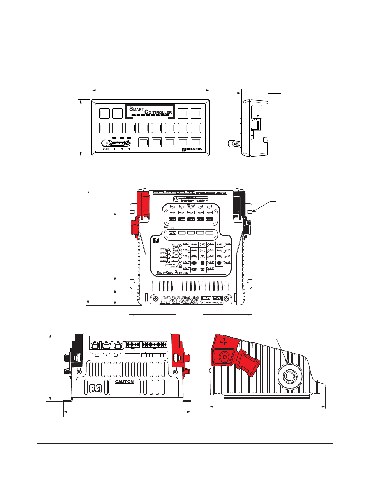
Figure 3.1 Dimensions of the control head .........................................................................................17
Figure 3.2 Dimensions of the siren amplier/relay module ................................................................17
Figure 3.3 Overview of Convergence Network Connections .............................................................19
Figure 3.4 Serial port locations ...........................................................................................................21
Figure 3.5 Congurable activation options for 10 A relays with active-low capability ......................... 22
Figure 3.6 Connection for 10 A solid-state auxiliary relays ...................................................................... 23
Figure 3.7 Connection for 2 A solid-state relays .................................................................................24
Figure 3.8 Connections for discretely wired SignalMaster .................................................................25
Figure 3.8 Switch operation for Inputs 1 to 4 .....................................................................................26
Figure 3.9 Connections for discrete-wire SignalMaster .....................................................................26
Figure 3.10 Connections for the Park Input circuit .............................................................................27
Figure 3.11 Connections for two speakers ..........................................................................................28
Figure 3.12 Connections for horn-ring transfer circuit .......................................................................30
Figure 3.13 Connections for radio rebroadcast ...................................................................................31
Figure 3.14 Connections for the control head .....................................................................................32
Figure 3.15 Microphone connected to the control head ......................................................................34
Figure 3.16 Negative ground connection for the control head............................................................36
Figure 4.1 Default control head button for radio rebroadcast .............................................................37
Figure 4.2 Gain control for radio rebroadcast (siren amplier/relay module) ....................................38
Figure 4.3 Gain control for PA (amplier/relay module) ....................................................................38
Figure 4.4 Gain control for PA (control head) ....................................................................................39
Figure 5.1 Slots for mounting hardware ..............................................................................................41
Figure 5.2 Bracket attached to back of control head ...........................................................................42
SmartSiren Platinum Convergence Network
5

Contents
Figure 5.3 Brackets attached to control head and mounting surface ..................................................42
Figure 6.1 LEDs and buttons associated with Program Mode settings ...............................................44
Figure 6.2 Keep-Alive Timeout durations ...........................................................................................45
Figure 7.1 SSP2000B default conguration for control head .............................................................48
Figure 7.2 SSP2000B control head and ignition timer inputs .............................................................48
Figure 7.3 SSP3000B default conguration for control head .............................................................49
Figure 7.4 SSP3000B contol head and ignition timer inputs ..............................................................49
Figure 7.5 Default conguration for steering wheel switches wired to control head .........................50
Figure 7.6 LED indicators and fuses on upper part of siren amplier/relay module ..........................51
Figure 7.7 LED indicators on lower label of siren amplier/relay module ........................................52
Figure 7.8 LED programming indicators on the control head ............................................................53
Figure 8.1 Installing the control head labels .......................................................................................54
Figure 8.2 Safety message card (left) and siren safety labels (right) ..................................................55
Figure 10.1 Control head removed from mounting surface ................................................................58
Figure 10.2 Control head removed from mounting brackets ..............................................................58
Figure 10.3 Slide switch removed from control head .........................................................................59
Figure 10.4 External parts assembly (SSP3000B shown) ...................................................................61
Figure 10.5 Locking tabs on red insulator ...........................................................................................62
6
SmartSiren Platinum Convergence Network

CHAPTER 1
Safety Messages for Installers and Operators
For your safety, read and understand this manual thoroughly before installing, operating, and
servicing the SmartSiren Platinum siren amplier/relay module. The safety messages presented in this
chapter and throughout the manual are reminders to exercise extreme care at all times. In addition,
read and understand the safety instructions to installers (doc. no. 256A692), and keep it close at hand
for reference.
To download copies of this manual, go to www.fedsig.com or call the Federal Signal Service
Department at 1-800-433-9132 (708-534-3400) 7 a.m. to 5 p.m., Monday through Friday (CT).
Safety Messages to Installers of Sound/Light Systems
People’s lives depend on your proper installation and servicing of Federal Signal products. It is
important to read and follow all instructions shipped with this product. In addition, listed below are
some other important safety instructions and precautions you should follow:
Before Installation
Qualications
• To properly install an electronic siren, you must have a good understanding of automotive
electrical procedures and systems, along with prociency in the installation and service of safety
warning equipment. Always refer to the vehicle’s service manuals when performing equipment
installations on a vehicle.
Sound Hazards
• Your hearing and the hearing of others, in or close to your emergency vehicle, could be damaged
by loud sounds. This can occur from short exposures to very loud sounds, or from longer
exposures to moderately loud sounds. For hearing conservation guidance, refer to federal, state,
or local recommendations. OSHA Standard 1910.95 offers guidance on “Permissible Noise
Exposure.”
• All effective sirens and horns produce loud sounds (120 dB) that may cause permanent hearing
loss. Always minimize your exposure to siren sound and wear hearing protection. Do not sound
the siren indoors or in enclosed areas where you and others will be exposed to the sound.
• Federal Signal siren amplier/relay modules and speakers are designed to work together as a
system. Combining a siren and speaker from different manufacturers may reduce the warning
effectiveness of the siren system and may damage the components. You should verify or test your
SmartSiren Platinum Convergence Network
7

Chapter 1: Safety Messages for Installers and Operators
combination to make sure the system works together properly and meets federal, state and local
standards or guidelines.
During Installation
• Do NOT get metal shavings inside the product. Metal shavings in the product can cause the
system to fail. If drilling must be done near the unit, place an ESD approved cover over the unit to
prevent metal shavings from entering the unit. Inspect the unit after mounting to be sure there are
no shavings present in or near the unit.
• Do NOT connect this system to the vehicle battery until ALL other electrical connections are
made, mounting of all components is complete, and you have veried that no shorts exist. If
wiring is shorted to vehicle frame, high current conductors can cause hazardous sparks resulting in
electrical res or ying molten metal.
• Be sure the siren amplier/relay module and speaker(s) in your installation have compatible
wattage ratings.
• In order for the electronic siren to function properly, the ground connection must be made to the
NEGATIVE battery terminal.
• Sound output will be severely reduced if any objects are in front of the speaker. If maximum
sound output is required for your application, you should ensure that the front of the speaker is
clear of any obstructions.
• Install the speaker(s) as far forward on the vehicle as possible, in a location which provides
maximum signaling effectiveness and minimizes the sound reaching the vehicle’s occupants.
Refer to the National Institute of Justice guide 500-00 for further information.
• Mounting the speakers behind the grille will reduce the sound output and warning effectiveness of
the siren system. Before mounting speakers behind the grille, make sure the vehicle operators are
trained and understand that this type of installation is less effective for warning others.
• Sound propagation and warning effectiveness will be severely reduced if the speaker is not facing
forward. Carefully follow the installation instructions and always install the speaker with the
projector facing forward.
• Do NOT install the speaker(s) or route the speaker wires where they may interfere with the
operation of airbag sensors.
• Installation of two speakers requires wiring speakers in phase.
• Never attempt to install aftermarket equipment, which connects to the vehicle wiring, without
reviewing a vehicle wiring diagram available from the vehicle manufacturer. Insure that your
installation will not affect vehicle operation and safety functions or circuits. Always check vehicle
for proper operation after installation.
• Do NOT install equipment or route wiring or cord in the deployment path of an airbag.
• If a vehicle seat is temporarily removed, verify with the vehicle manufacturer if the seat needs to
be recalibrated for proper airbag deployment.
• Locate the control head so the vehicle, controls, and microphone can be operated safely.
8
SmartSiren Platinum Convergence Network

Chapter 1: Safety Messages for Installers and Operators
• When drilling into a vehicle structure, be sure that both sides of the surface are clear of anything
that could be damaged.
After Installation
• After installation, test the siren and light system to ensure that it is operating properly.
• Test all vehicle functions, including horn operation, vehicle safety functions and vehicle light
systems, to ensure proper operation. Ensure that installation has not affected vehicle operation or
changed any vehicle safety function or circuit.
• After testing is complete, provide a copy of these instructions to the instructional staff and all
operating personnel.
• File these instructions in a safe place and refer to them when maintaining or reinstalling the
product.
Failure to follow all safety precautions and instructions may result in property damage, serious injury,
or death.
RETAIN AND REFER TO THESE MESSAGES
Safety Messages to Operators of Sound/Light Systems
People’s lives depend on your safe operation of Federal Signal products. It is important to read and
follow all instructions shipped with the products. In addition, listed below are some other important
safety instructions and precautions you should follow:
• Do not attempt to activate or de-activate the light system control while driving in a hazardous
situation.
• Although your warning system is operating properly, it may not be completely effective. People
may not see or heed your warning signal. You must recognize this fact and continue driving
cautiously.
• Also, situations may occur which obstruct your warning signal when natural and man-made
objects are between your vehicle and others, such as raising your hood or trunk lid. If these
situations occur, be especially careful.
• All effective sirens and horns produce loud sounds that may cause, in certain situations, permanent
hearing loss. You and your passengers should consider taking appropriate safety precautions, such
as wearing hearing protection.
• In order to be an effective warning device, this product produces bright light that can be hazardous
to your eyesight when viewed at a close range. Do not stare directly into this lighting product at a
close range or permanent damage to your eyesight may occur.
• It is important that you fully understand how to safely operate this warning system before use.
• You should only operate your vehicle and its light/sound system in accordance with your
department’s Standard Operating Procedures.
SmartSiren Platinum Convergence Network
9

Chapter 1: Safety Messages for Installers and Operators
• If a selected function does not perform properly or if any of the lamps remain illuminated when
the control is off, disconnect the power connector from the control unit and contact the nearest
service center.
• At the start of your shift, you should ensure that the entire warning light system and the siren
system is securely attached and operating properly.
• The effectiveness of an interior mounted warning light depends on the clarity, the tiniting, and the
angle of the glass it is being placed behind. Tinting, dirt, defects, and steeply angled glass reduce
the light output of the warning light. This may reduce the effectiveness of the light as a warning
signal. If your vehicle has dirty, tinted, or steeply angled glass, use extra caution when driving
your vehicle or blocking the right of way with your vehicle.
• Suction cup mounting is for temporary applications only. The unit should be removed from the
window and stored securely when not in use. Temperature changes and sunlight can cause suction
cups to lose holding power. Periodically check the unit to be sure the suction cups have a rm grip
on the mounting surface. An improperly secured light could fall off of the vehicle causing injury
and damage.
• The holding power of magnetic mounting systems is dependent upon surface nish, surface
atness, and thickness of the steel mounting surface.
Therefore, to promote proper magnetic mounting:
✓
The mounting surface and magnets must be kept clean, dry, and free of foreign particles that
prevent good surface contact.
✓
Ensure that the mounting surface is at.
✓
A magnet mounting system should not be used on vehicles with vinyl tops.
✓
To prevent the light assembly from sliding on mounting surface, avoid quick acceleration and
hard stops.
Failure to follow these precautions may result in property damage, serious injury, or death.
RETAIN AND REFER TO THESE MESSAGES
10
SmartSiren Platinum Convergence Network

CHAPTER 2
An Overview of the SmartSiren Platinum
The SmartSiren Platinum siren amplier/relay module is a full-featured, programmable electronic
siren and light control system. State-of-the-art microprocessor technology is used to create a system
with a small, compact control head and a siren amplier/relay module that can be installed in the
trunk, under the dashboard, or under the seat of any vehicle with a 12 V negative ground system.
The module provides the automatic, simultaneous light and siren activation required by some
jurisdictions. A security shotgun timer is also provided to minimize the possibility of unauthorized
shotgun release. The module has six easily accessible Convergence™ Network serial ports that
connect the control head and any serially-controlled Federal Signal product. A variety of system
features can be programmed with the Convergence Network Conguration Software from a computer
via a crossover Ethernet cable that connects the control head. System features include ash patterns,
siren tones, and momentary, push-on/push-off, or timed relay operation. Programming does not
require disassembling or removing any hardware from the vehicle.
Siren, PA, and Speakers
The Smart Siren produces wail, yelp, priority, and hi-lo siren tones, as well as an air horn sound. The
horn-ring transfer feature enables the driver to control siren tones by pressing the horn button. Public
address is available with the Federal Signal microphone, which is included with the system. Radio
rebroadcast is also available. The Model SSP3000B module can drive one or two 11-ohm impedance,
100 W speakers, and the Model SSP2000B module can drive one. Two speakers must always be
connected in parallel and in phase.
Lightbars and SignalMasterTM Control
Compatible lightbars include full featured, serially-controlled Federal Signal Arjent® S2, Legend®,
ValorTM, and Integrity® as well as the SpectraLuxTM ILS Series of interior-mounted lightbars. A
full-featured SignalMasterTM controller is integrated into the system. In addition, ash rates and
patterns, lightbar dimming, and other options can be programmed with the Convergence Network
Conguration Software.
Programmable Solid-State Auxiliary Relays
The Model SSP3000B has 14 solid-state relays: ten 10 A high-low and four 3 A high.
The Model SSP2000B has 11 solid-state relays: one 10 A high-low, six 10 A high, and four 2 A high.
SmartSiren Platinum Convergence Network
11

Chapter 2: An Overview of the Convergence Network
Programmable Input Circuits
Both models of the siren amplier/relay modules have connections for four relay input circuits. Relay
inputs 1 and 2 are active-low inputs that activate a switch when pulled to ground. Relay inputs 3
and 4 are active-high inputs that activate a switch when pulled to 12 Vdc battery voltage. The inputs
are most commonly used for switches that send a signal to the siren amplier/relay module when
a condition in the vehicle changes. Changes may include the opening of a trunk or door, a rise in
vehicle temperature, or the release of a gun lock.
The control head has connections for four active-low inputs that activate when pulled to ground.
Similar to the relay circuits, they can be congured to operate with the Convergence system control
head or with the congurable switches on the steering wheel of the Ford Police Interceptor.
LED Indicators and Visual Diagnostics (Model SSP3000B Only)
LEDs visible just below the surface of the siren amplier/relay module indicate when power is
supplied to the auxiliary outputs and if the module is transmitting and receiving data. LEDs also
indicate when a signal is received by the four input circuits and if the lightbar is functioning.
Externally mounted mini-blade fuses for the siren, horn-ring circuit, SignalMaster, and auxiliary
relays have LEDs that glow when the fuse fails, making them easy to spot.
All buttons on the control head glow when the system is on. Pressed buttons turn bright to indicate
that the function they control is active. LEDs under the SmartSiren logo mimic these active
SignalMaster patterns: Left, Right, Center-Out, or Warn patterns 1 to 4. An LED glows over the
position in which the slide switch is placed.
System Specications
Input Voltage 11 Vdc to 16 Vdc
Polarity Negative ground only
Operating Temperature Range -40 °C to +65 °C (relays at full power)
-40 °C to +80 °C (relays at 60 percent power)
Standby Current Less than 0.2 A
Dimensions:
Amplier/relay module
Height 4.22 in (10.72 cm)
Width 7.94 in (20.17 cm)
Length 6.81 in (17.30 cm)
Net Weight 5.40 lb (2.45 kg)
Control head
Height 3.26 in (8.28 cm)
Width 1.62 in (4.11 cm)
Length 6.80 in (17.27 cm)
Net Weight 0.8 lb (0.36 kg)
Shipping Weight 10.0 lb (4.53 kg)
12
SmartSiren Platinum Convergence Network

Chapter 2: An Overview of the Convergence Network
Siren Specications
Speakers SSP2000B: one 100 W, 11-ohm speaker
SSP3000B: one or two 100 W, 11-ohm speakers
Operating Current (no lamps on) 9 A (nominal), (13.6 V battery, 11-ohm load at high power)
Frequency Range 725 to 1 600 Hz
Nominal Cycle Rate Wail: 12 cycles per minute
Yelp: 180 cycles per minute
Priority: 370 cycles per minute
High-Low: 60 cycles per minute
Nominal Voltage Output 64 V peak-to-peak (siren tones)
Audio Response 300 Hz to 3,000 Hz ± 3 dB
Audio Power 45 W in PA Mode (typical with 1.4 V peak-to-peak input)
Harmonic Distortion Less than 10 percent from 5 to 45 W
Input Impedance (PA) 4,000 ohms (nominal)
Siren Tone Compliances SAE J1849 JUL89
SignalMaster Specications (Model SSP3000B only)
Fuse 20 A (halogen or LED)
Output Drive Capability (Total) Eight lamps at 27 W each
Normal Flash Rate
Directional and Warn Approximately 35 patterns per minute
Fast Flash Rate
Directional and Warn Approximately 45 patterns per minute
Relay Specications
Model SSP3000B Fuse Capability AUX 1 to 8: 10 A (high)
AUX 9 and 10: 10 A (high-low)
AUX 11 to 14: 2 A high
Model SSP2000B Fuse Capability AUX 1 to 6: 10 A (high)
AUX 10: 10 A (high-low)
AUX 11 to 14: 2 A (high)
Flash Rates 75 ashes per minute
90 ashes per minute
120 ashes per minute
200 ashes per minute
300 ashes per minute
SmartSiren Platinum Convergence Network
13

Chapter 2: An Overview of the Convergence Network
SmartSiren Platinum Kit Contents
Table 2.1 (Model SSP2000B) and 2.2 (SSP3000B) lists the parts included with the SmartSiren
Platinum kit. After unpacking the kit, examine it for damage that may have occurred in transit. If the
product has been damaged, le a claim immediately with the carrier stating the extent of damage.
Carefully check all envelopes, shipping labels, and tags before removing or destroying them. Ensure
all parts in the packing list are included in the shipment. If any parts are missing, call Federal Signal
Customer Support at 1-800-264-3578, 7 a.m. to 5 p.m., Monday through Friday, Central Time.
Table 2.1 SSP2000B kit contents
Qty. Description Part Number
1 SSP2000B Control Head 853600632-SSP2K
1 SSP2000B Siren Amplier/Relay Module 853600629-04
1 Cable Assy., RS485, 25 ft 1751357-02
1 Cable Assy., Control 17500307
1 Cable Assy., Auxiliary Relay 1751541
1 Cable Assy., SignalMaster and Inputs 1751542-NY
1 Cable Assy. 17500308
2 Bracket, Mounting, Control Head 85361065
2 Screw, Mach. Pan Head, #6-32 7000A404-05
2 Screw, Cap, Hex Head, 1/4"-20 7002A000-12
2 Screw, Pan Head, #10, Thread-Forming 7011A047-08
2 Lock Washer, Split, #6 7074A001
2 Lock Washer, Ext, Tooth, 1/4" 7075A007
1 Keyhead Legends, Scored Sheet 8572294
1 Microphone with Modular Plug 256B577-03
1 Fuse, 5 A, Mini Blade 148181-03
7 Fuse, 10 A, Mini Blade 148181-05
1 Fuse, 20 A, Mini Blade 148181
1 Quick Reference Guide 2562503
1 Card, Safety Instructions 256B691
1 Instruction Sheet, Operators Safety Messages 256A692
1 Label, Warning, Siren/Speaker 1612339
14
SmartSiren Platinum Convergence Network

Chapter 2: An Overview of the Convergence Network
Table 2.2 SSP3000B kit contents
Qty. Description Part Number
1 SSP3000B Control Head 853600632
1 SSP3000B Siren Amplier/Relay Module 853600629
1 Cable Assy., RS485, 25 ft 1751357-02
1 Cable Assy., Control 17500307
1 Cable Assy., Auxiliary Relay 1751541
1 Cable Assy., RJ45 Ethernet Crossover 1751532
1 Cable Assy., SignalMaster and Inputs 1751542-01
1 Cable Assy. 17500308
1 Cable Assy., RJ45, Ethernet Crossover 1751532
2 Bracket, Mounting, Control Head 85361065
2 Screw, Mach. Pan Head, #6-32 7000A404-05
2 Screw, Cap, Hex Head, 1/4"-20 7002A000-12
2 Screw, Pan Head, #10, Thread-Forming 7011A047-08
2 Lock Washer, Split, #6 7074A001
2 Lock Washer, Ext, Tooth, 1/4" 7075A007
1 Keyhead Legends, Scored Sheet 8572294
1 Microphone with Modular Plug 256B577-03
1 Fuse, 5 A, Mini Blade, LED Indicator 148210-04
7 Fuse, 10 A, Mini Blade, LED Indicator 148210-06
1 Fuse, 20 A, Mini Blade, LED Indicator 148210-08
1 Quick Connect Guide 25600152
1 Quick Reference Guide 2562503
1 Card, Safety Instructions 256B691
1 Instruction Sheet, Operators Safety Messages 256A692
1 Label, Warning, Siren/Speaker 1612339
SmartSiren Platinum Convergence Network
15
CHAPTER 3
Connecting the Convergence Network
Before permanently installing the SmartSiren Platinum system, plan all wire routings and select the
mounting locations for the siren amplier/relay module and control head. Also read and understand
all instructions included with related equipment before installing it.
Selecting Mounting Locations
When fastened to the back of the control head, the mounting bracket covers the wiring connectors and a
supplemental control for the gain or volume of the radio rebroadcast feature. To facilitate the installation
of the SmartSiren Platinum system, select mounting locations for the control head and the siren amplier/
relay module before permanently mounting them in the vehicle. After completing the wiring described in
this chapter, refer to the instructions for mounting the control head and the siren amplier/relay module in
Chapter 5 on page 40.
AIRBAG DEPLOYMENT: Do not install equipment or route wiring in the
deployment path of an airbag. Failure to observe this warning will reduce the
effectiveness of the airbag or potentially dislodge the equipment, causing
serious injury or death.
SEAT REMOVAL PRECAUTION: If a vehicle seat is temporarily removed, verify
with the vehicle manufacturer if the seat needs to be recalibrated for proper
airbag deployment.
UNIT REQUIRES AIR FLOW (SSP3000B ONLY): The siren amplier/relay module
is cooled by an internal fan. Do not install it in areas where the air ow is
restricted. Do not mount the unit near a heater duct or under the hood.
MODULE IS NOT WATERPROOF: The housing of the siren amplier/relay module
is NOT waterproof. The module must be mounted in a location that is sheltered
from falling rain, snow, standing water, etc.
For the control head, select a mounting location that allows the vehicle, controls, and microphone to
be operated safely under all driving conditions. To identify safe mounting areas for equipment inside
the vehicle, consult the vehicle manufacturer’s guidelines. To avoid driver distraction and unreliable
switch activation, the mounting location must not allow any movement of the control head. Do not
select a headded surface for the mounting location of the control head. For the siren amplier/relay
module, suggested mounting locations are under the dash, under the front seat, or in the trunk under
the rear deck near the rear-seat speakers. Wiring connectors are located on the back of the siren
amplier/relay module. Terminals for the ground and power connections are located on each side
toward the rear.
16
SmartSiren Platinum Convergence Network
Chapter 3: Wiring the Convergence Network
FRONT VIEW RIGHT SIDE VIEW
IMPORTANT: To maintain the reliability of the Model SSP3000B amplier/relay module, which is
cooled by a fan, ensure that there is enough room for the ow of air.
Figure 3.1 Dimensions of the control head
3.25 in
(8.25 cm)
7.49 in
(19.03 cm)
6.80 in
(17.27 cm)
PC
ONLY
CONNECT
Figure 3.2 Dimensions of the siren amplier/relay module
TOP VIEW
4.50 in
(11.43 cm)
INSTALLER-SUPPLIED
#10-32 MOUNTING
HARDWARE REQUIRED
1.50 in
(3.81 cm)
MOUNTING
SLOTS
(4 PLACES)
4.22 in
(10.72 cm)
1.05 in
(2.66 cm)
7.94 in
(20.17 cm)
REAR VIEW
57
AUX
+
3 1
PARK
2 33445 6 7 8
1
P
11 1 1 1 12 2 3 4
AUX
INPUT
10 8 642
SERIAL PORTS
RADIO
RING
SPKR
RADIO
HORN
SPKR
9
DO NOT EXCEED 5 AMPS
MAXIMUM ON HORN RING
CIRCUIT. SEE INSTALLATION
INSTRUCTIONS
SM
+12V
7.94 in
(20.17 cm)
SmartSiren Platinum Convergence Network
SIDE VIEW
7.58 in
(19.25 cm)
INTERNAL FAN
(ON SSP3000 ONLY)
290A7541
17

Chapter 3: Wiring the Convergence Network
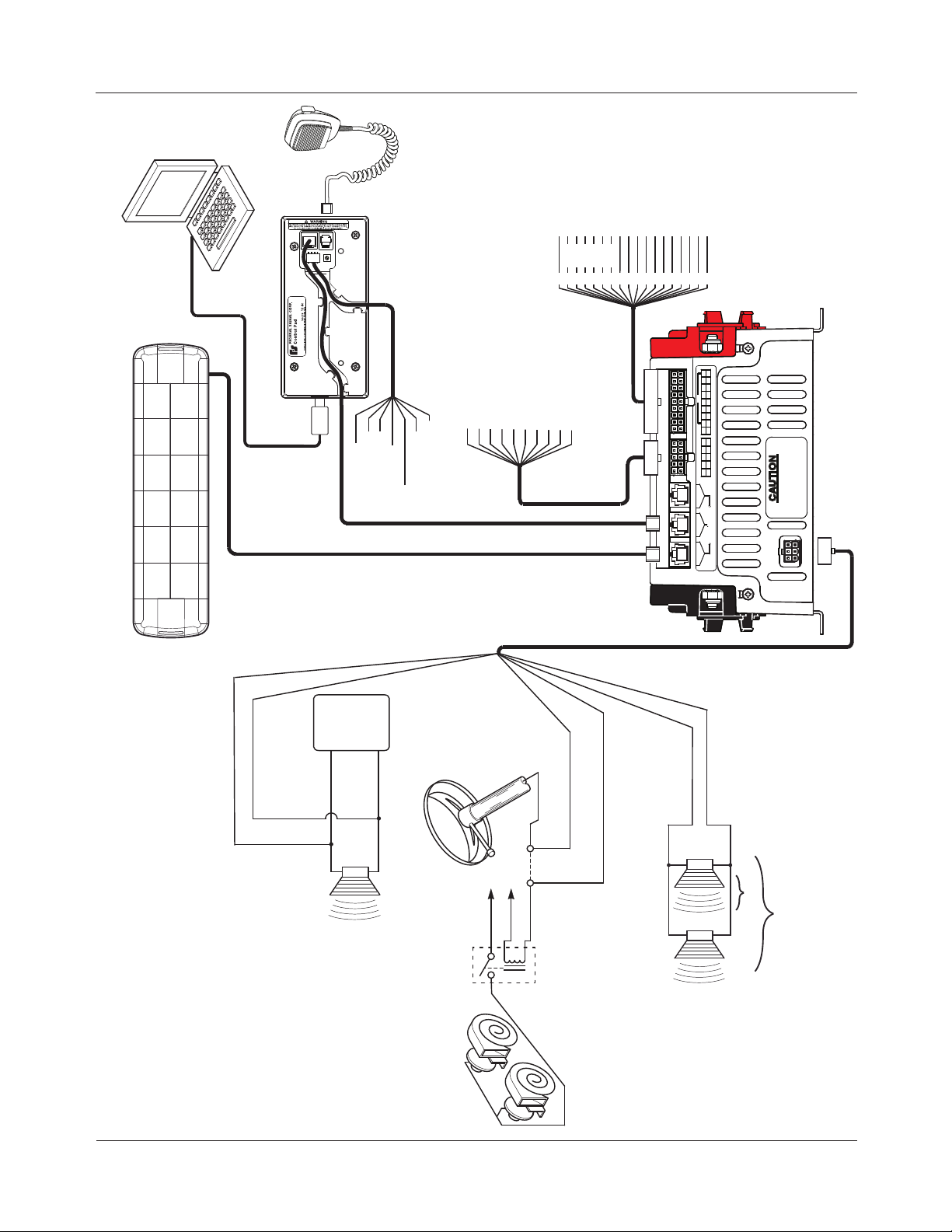
Overview of the Convergence Network Connections
The Convergence Network system has these types of connections via cables and locking connectors
included with the kit (see Figure 3.3):
Connections for the siren amplier/relay module:
◆ Three “plug and play” serial ports that communicate on the Federal Signal Convergence network
with the control head, compatible lightbars, and the Federal Signal Model 660100 Relay Module/
Two-Channel Flasher.
◆ Seven to ten 10 A auxiliary solid-state relays (cable assembly 1751541)
◆ Four low-current auxiliary solid-state relays and a Park Input circuit (cable assembly 1751542-01
or 1751542-NY)
◆ SignalMaster directional warning lights (cable assembly 1751542-01, SSP3000B only)
◆ Four auxiliary relay inputs (cable assembly 1751542-01 or 1751542-NY)
◆ Speakers and a horn ring circuit (cable assembly 17500307)
◆ Power terminals for negative ground and positive 12 Vdc
Connections for the control head:
◆ Four active-low input circuits that activate when pulled to ground. They can be congured to
operate with the SSP3000B system control head or with the switches on the steering wheel of the
Ford Police Interceptor.
◆ Connections to the siren for battery ground (-GND) and +12 Vdc switched by ignition
◆ Connection for the Federal Signal public address microphone (P/N 258B577-03)
◆ Convergence Network 25-foot cable that connects the control head to the siren amplier
(1751532)
◆ Optional ignition input to run long timers
For installation details, see pages 20 through 36.
For instructions on conguring the operation of the devices connected through the Convergence
Network, see the “Converrgence Conguration Software Manual” P/N 2562418.
18
SmartSiren Platinum Convergence Network
Chapter 3: Wiring the Convergence Network
VEHICLE HORNS
290A7825
*RED TO 12 V CONNECTION
INPUT 1 GRAY
*RED
INPUT 2 WHT/YEL
INPUT 3 PURPLE
INPUT 4 BLUE
*YELLOW IF THE IGNITION
TIMER FUNCTION IS USED.
(CONNECT THROUGH FUSE.)
ACTIVATED BY IGNITION
(OR TO +BAT IF THE IGNITION
TIMER FUNCTION IS USED)
1 AUX. RELAY 1 (BLACK)
2 AUX. RELAY 2 (GREEN)
3 AUX. RELAY 3 (WHITE)
4 AUX. RELAY 4 (YELLOW)
5 AUX. RELAY 5 (GRAY)
BLACK (GROUND)
*YELLOW (IGN. INPUT)
SM 1 (WHITE)
SM 2 (BROWN)
SM 1
2
1
6 AUX. RELAY 6 (ORANGE)
7 AUX. RELAY 7 (VIOLET)
8 AUX. RELAY 8 (RED)
9 AUX. RELAY 9 (BLUE)
10 AUX. RELAY 10 (BROWN)
SM 8 (BLUE)
SM 3 (GREEN)
SM 4 (ORANGE)
SM 7 (YELLOW)
SM 5 (VIOLET)
SM 6 (GRAY)
SM 4
SM 5
SM 6
SM 2
SM 3
45678
3
INPUT 1 (WHT/BRN)
INPUT 2 GND (WHT/GRN)
INPUT 3 WHT/VLT (+12 V)
INPUT 4 WHT/GRY (+12 V)
11121314151617
*PARK/NEUTRAL INPUT (BLK)
AUX. RELAY 11 (WHT/RED)
AUX. RELAY 12 (WHT/ORG)
AUX. RELAY 13 (WHT/YEL)
AUX. RELAY 14 (WHT/BLUE)
SM POWER OUT (RED)
+
16
P
INPUT
5 6 7 8
SM
4
4
3
2 3
AUX
1
11 1 1 1 12 2 3 4
P
PARK
+12V
+
2
4
3 1
5
AUX
7
9
10 8 6
SERIAL PORTS
-BAT +BAT
*PARK/NEUTRAL INPUT DISABLES ALL
TONES EXCEPT AIR HORN AND MANUAL
OR SMALL FLASHING LIGHTS.
INSTRUCTIONS
DO NOT EXCEED 5 AMPS
MAXIMUM ON HORN RING
CIRCUIT. SEE INSTALLATION
SPKR
SPKR
RING
RING
RADIO
RADIO
RADIO
TWO-WAY
BROWN ZIP CORD
Figure 3.3 Overview of Convergence Network Connections
BROWN ZIP CORD
STEERING COLUMN
RADIO
SPEAKER
SmartSiren Platinum Convergence Network
HORN RING
OF SIREN FOR
5 A FUSE ON TOP
TO BATTERY
SW
SPST RELAY
(INSTALLER-SUPPLIED)
CUT
WIRE
WHITE/YELLOW
TO HORN RING
TO HORN RING SIDE OF CUT WIRE
WHITE
TO HORN OR HORN RELAY
BLUE
BROWN
100 W
200 W (SSP3000B ONLY)
19

Chapter 3: Wiring the Convergence Network
Preparing for the Convergence Network Installaton
HIGH CURRENT ARCING: Do not connect this system to the vehicle battery until
ALL other electrical connections are made and you have veried that no shorts
exist. High current conductors can cause hazardous sparks or burning wire
resulting in electrical res.
DRILLING PRECAUTIONS: When drilling holes, check the area into which you are
drilling to be sure that you do not damage vehicle components while drilling. All
drilled holes should be deburred and all sharp edges should be smoothed. All
wiring routings going through drilled holes should be protected by a grommet or
convolute/split loom tubing.
To prepare the vehicle for connecting the Convergence Network system:
1. After planning where to route the wires and cables for the system components—such as Federal
Signal warning lights, directional lights, and speakers—drill the holes for the wiring. Smooth,
deburr, and insert a grommet in the holes.
2. Mount the system components according to the instructions included with each product.
The next sections describe how to connect and wire each system component to the siren amplier/
relay module.
Connecting the Convergence Network
There are three network ports on the upper left rear corner of the siren amplier/relay module. These
ports connect Federal Signal network devices through RS-485 communication cables.
Network devices include:
◆ The system control head, which must be connected to a serial port on the siren amplier/relay
module. Use the 25-foot FS Convergence Network cable (P/N 1751357-02) to connect the
control head to the module.
◆ Exterior-mounted, full-size lightbars, such as the Arjent
Congurable options include ash patterns and functions, such as dimming, takedowns, and alley
lights.
◆ ILS System lightbars that include three models of single-level LED lightbars — Front ILS, Rear
Lower ILS, and Rear Upper ILS — that mount on the inside of a vehicle windshield. Congurable
options include ash patterns and functions, such as dimming, takedowns, and alley lights.
Figure 3.4 on page 21 shows the network connections on the back of the siren amplier/relay module.
For instructions on mounting network devices, refer to the instructions included with the products.
S2, Legend®, ValorTM, and Integrity®.
®
20
SmartSiren Platinum Convergence Network
 Loading...