

Page 1

2561007E
REV. E 1002
Printed in U.S.A.
INSTRUCTION SHEET
SIGNALMASTER™ MODEL 331102
SAFETY MESSAGE TO INSTALLERS
People’s lives depend on your safe installation of our products.
It is important to read, understand and follow all instructions
shipped with the products. In addition, listed below are some other
important safety instructions and precautions you should follow:
• To properly install this light: you must have a good
understanding of automotive electrical procedures
and systems, along with proficiency in the installation and use of safety warning equipment.
• DO NOT install equipment or route wiring in the
deployment path of an air bag.
• When drilling into a vehicle structure, be sure that
both sides of the surface are clear of anything that
could be damaged.
• In order for the light to function properly, a good
ground connection must be made. At a minimum, it
must be attached to a solid metal body or chassis
part that will provide an effective ground path as
long as the light system is to be used.
• Locate light control so the VEHICLE and CONTROL can be operated safely under all driving
conditions.
• Do not attempt to activate or deactivate light control
while driving in a hazardous situation.
• This product controls high intensity LED devices. To
prevent eye damage, DO NOT stare into the light
beam at close range.
• You should frequently inspect the light to ensure
that it is operating properly and that it is securely
attached to the vehicle.
• File these instructions in a safe place and refer to
them when maintaining and/or reinstalling the
product.
Failure to follow all safety precautions and instructions may
result in property damage, serious injury, or death to you or
others.
I. GENERAL.
The Federal Signal SignalMaster Model 331102 is an
economical, low profile, solid state, directional light control that is
designed to operate with any of Federal Signal’s SignalMaster
series eight-lamp directional lights. This control will also operate
two sets of external lamps (Federal Signal Models 320102,
SMLED1, 320112, and 320721, or other 50 watt lamps). The unit
is reversed polarity protected to avoid damage if the positive and
negative power connections are connected incorrectly.
This model provides three distinctive directional signals, left
arrow, right arrow, and center out. An alternating flash pattern
produces a warning signal for use when a directional signal may
not be appropriate. In addition, an auxiliary flash pattern
alternately flashes the external lamps. The directional and
alternating flash patterns can also be selected to operate faster, or
with decreased current draw. The slide switch overrides the
WARN and AUX functions.
When normal directional signal operation is selected, the
lamps individually activate sequentially in a sweeping motion
until all eight are illuminated. When LOW (current) operation is
selected, the lamps turn on/off in sequence until a pattern is
completed. When FAST is selected, the chosen pattern sequences
at an increased rate.
FOR
An auxiliary input and output are provided for integrating
external controls and lights into the SignalMaster system. When
properly connected, a positive (+) 12 volts applied to the AUX IN
terminal will activate the alternating flash pattern. The AUX OUT
terminal can activate a ground-activated relay (user-supplied)
when the AUX switch is operated.
WARNING
These lights are intended for secondary warning only.
They are not intended for use as a primary warning
system.
II. SPECIFICATIONS.
Input Voltage 11VDC to 16VDC.
Polarity Negative ground only.
Operating Temperature -30° C to +65° C.
Range
Standby Current Zero amperes.
+BAT Fuse 25 amperes.
+IGNITION Fuse 1 ampere.
AUX OUT Fuse 1 ampere.
Output Drive
Capability (Total)
Directional 8, 27 watt lamps.
Auxiliary 4, 27 watt lamps (2 per output) or
2, 50 watt lamps (1 per output).
Normal Flash Rate:
Directional 35 patterns/min.
Warn 60 patterns/min.
Auxiliary 95 patterns/min.
Fast Flash Rate:
Directional 60 patterns/min.
Warn 95 patterns/min.
Auxiliary 95 patterns/min.
Dimensions:
Height 1-1/2"
Width 6-1/8"
Depth 5"
Shipping Weight 2.5 lbs.
III. INSTALLATION.
A. SignalMaster Light Assembly.
Install the light assembly as described in the instructions packed with the 320340 universal mounting kit. Route the
cable near the eventual location of the control unit.
B. Control Unit.
WARNING
When installing equipment inside air bag equipped vehicles, the installer MUST ensure that the equipment is
installed ONLY in areas recommended by the vehicle
manufacturer.
Failure to observe this warning will reduce the effectiveness of the air bag, damage the air bag, or potentially
damage or dislodge the equipment, causing serious injury
or death to you or others.
Page 2
control unit to be mounted in a variety of positions. To install the
B
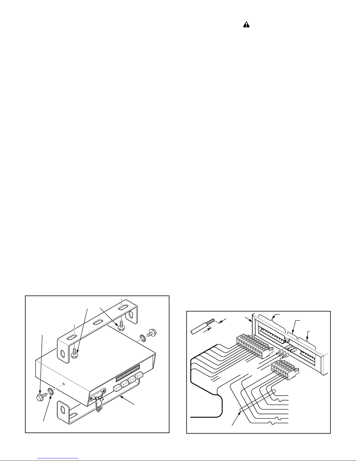
See figure 1. The supplied mounting bracket allows the
control unit, proceed as follows:
CAUTION
Install the control unit in an adequately ventilated area.
Never install near heater ducts.
NOTE
When selecting a mounting location for the control unit,
it is necessary to keep in mind the SignalMaster cable
length. Plan wiring and cable routing before installation.
1. Select a mounting location for the control unit that
allows the vehicle and controls to be operated safely at all times.
2. Use the mounting bracket as a template and scribe
two drill position marks at the selected mounting location.
CAUTION
Before drilling holes in ANY part of a vehicle, be sure that
both sides of the mounting surface are clear of parts that
could be damaged; such as brake lines, fuel lines, electrical
wiring or other vital parts.
3. Drill two holes at the previously scribed position
marks.
4. Secure the mounting bracket to the mounting
surface with two user-supplied, thread-forming, 1/4-20 screws.
C. Electrical Connections.
WARNING
Failure to observe this WARNING may result in fire,
burns or blindness.
If shorted to vehicle frame, high current conductors can
cause hazardous sparks resulting in electrical fires or
molten metal.
DO NOT connect this system to vehicle battery until ALL
other electrical connections are made and mounting of all
components is complete.
Verify that no short circuits exist, before connecting to the
Positive (+) battery terminal.
SCREWS,THREAD FORM.,
USER SUPPLIED
1/4-20 x 3/8" SCREW,
HEX WASH. HD .(2)
WARN
AUX
1/4" LOCKWASHER,
EXT . T OOTH(2)
FAST
LOW
REVERSED AS SHOWN HERE,
IF IT BETTER SUITS YOUR SPECIFIC
NOTE: ONLY ONE BRACKET IS SUPPLIED.
MOUNTING REQUIREMENTS.
BRACKET MAY BE
Figure 1.
331102
290A2542-48
WARNING
Do not connect more than one, 6 or 8 head, halogen
SignalMaster assembly to a SignalMaster controller or the SignalMaster outputs of a SmartSiren.
Electrical fire or damage to the controller or siren
will result.
The control unit is supplied with a seven-position
connector, an eleven-position connector, and insulated spade
connectors (0.250" (1) and 0.187" (2)) to perform the electrical
installation. User-supplied, 14-gauge red and black wires are
required for the (+) BAT and (-) GND connections. User-supplied,
18-gauge red and green wires are required for the (+) IGNITION
and (-) CASE GROUND connections on the seven-position
connector. In addition, user-supplied 18-gauge wire is used for the
AUX IN, AUX OUT, and DASH LIGHTS connections. Using figure
2 as a guide, complete this portion of the installation as follows:
1. Power Connections.
CAUTION
To avoid damage and ensure proper operation, the red
and black wires MUST be installed as shown in figure 2.
a. Strip 1/4" of insulation off of each 14AWG red
and black wire. See figure 2. Crimp a 0.187" wide spade receptacle
on the red wire. Crimp the 0.250" wide spade receptacle on the
black wire.
b. Connect the red and black 14-gauge terminated
wires to the +BAT and GND positions as shown in figure 2.
c. Route the red and black 14-gauge wires
through the firewall and toward the battery. Connect the black
wire to a good frame ground near the battery. In most vehicles, a
wire from the negative terminal of the battery is routed and
attached to the body/frame at the fender. This is a convenient
point to connect the 14-gauge black wire. Do not connect the red
wire to the (+) positive terminal at this time.
d. Connect the 18-gauge red (IGNITION) and
green (CASE GROUND) wires to the connector as shown in figures
2 and 3.
IMPORTANT
The (+) IGNITION (18-gauge red) wire’s termination
point determines when the directional signal can be
activated. When the wire is attached to a vehicle fuse
that is powered when the ignition switch is in the run or
start position, the vehicle’s ignition switch must be in the
run or start position to operate the directional signal.
When the wire is attached to the vehicle battery, the
directional signal can be operated at any time. Note that
the unit draws no current when in the “off” position.
GREEN
ORANGE
VIOLET
GRAY
LIGHT OUTPUTS
YELLOW
BLUE
WHT/BLU
WHT/GRN
WHT/RED
WHT/ORN
RED
18 AWG DASH LIGHTS
1A
18 AWG AUX OUT
18 AWG AUX IN
18 AWG CASE GND.
14 AWG (-)GND
1A
18 AWG IGNITION
25A
14 AWG +BAT
POWER AND
+BAT
24 AMP.
+BAT/IGN
-2-
WIRE STRIPPING
TYPICAL
9 CONDUCTOR
CABLE FROM
SIGNALMASTER
320172
GRAY
YEL
BLUE
PRP
+BAT
1/4"
ORN
GRN
CUSTOMER SUPPLIED
331102
W
HT
BRN
EXTERNAL LAMP
CONNECTIONS
RED
+BAT
LAMP COM
GND.
Figure 2.
WHITE
BROWN
GROUND
CONTROL
LEADS
(-) GND
(-) CASE
GROUNG
AUX IN
AUX OUT
DASH
LIGHTS
290A2542-54B
Page 3

WIRE STRIPPING
TYPICAL
1/4"
STRIPPED
WIRES
TIP OF SMALL
SCREWDRIVER
Figure 3.
1. INSERT SCREWDRIVER
TIP INTO RECTANGULAR
HOLE.
2. INSERT STRIPPED WIRE
END IN ROUND HOLE.
3. REMOVE SCREWDRIVER.
290A4458
e. Select the desired termination point. As
applicable, route the 18-gauge red wire toward the vehicle fuse
block or through the firewall toward the battery. Install a usersupplied, 1-ampere, in-line fuse in the 18-gauge red wire as close
to the power source as possible and terminate as required.
f. Route the 18-gauge green wire to a known good
chassis ground near the 331102 control. To provide a good ground
connection, scrape any painted surface to bare metal.
2. AUX IN and AUX OUT Connections.
When a positive (+)12 volts is applied to the AUX IN
connection, the alternating flash pattern is activated.
The AUX OUT connection will provide a ground to
activate a ground-activated relay (user-supplied) when the AUX
switch is operated. To perform the wiring for these connections,
proceed as follows (see figures 2 and 3):
CAUTION
To avoid damage and ensure proper operation, the wires
MUST be installed in the seven- position connector as
shown in figure 3.
a. Connect a user-supplied 18-gauge wire to the
seven-position connector’s AUX IN connection. Route the wire to a
user-supplied external switch which will provide a positive (+) 12volts (such as Federal Signal Model SW400SS) when activated.
b. Connect a user-supplied 18-gauge wire to the
seven-position connector’s AUX OUT connection. Route the wire to
a user-supplied ground-activated relay for activation of an external
device. Install an in-line, user-supplied, 1 ampere fuse between the
control and the relay.
the eleven-position connector as shown in figures 2 and 3.
d. Connect the remaining SignalMaster wires to
e. If applicable, connect the external lamp ground
cables to the connector (positions 9 and 10) as shown in figures 2
and 3. Each of these two positions provides an alternating ground
signal to activate external lamps.
D. Inspection and Final Installation.
1. Ensure that there are no loose wire strands or other
bare wires which may cause a short circuit. Also, all wires must be
protected from any sharp edges which could eventually cut
through the insulation.
2. Plug the seven-position connector into the mating
connector on the control unit, and apply pressure until it locks into
place.
3. Plug the eleven-position connector into the mating
connector on the control unit, and apply pressure until it locks into
place.
4. Connect the remaining end of the 14-gauge red wire
from the +BAT spade connector to the (+) positive terminal of the
battery using an in-line, user-supplied fuseholder and 25A fuse.
Locate the fuse as near the battery as possible to protect the entire
length of wire.
5. Read and understand paragraph IV OPERATION,
and test for proper operation of all functions.
6. Secure the mounting bracket to the control unit
with the 1/4-20 hex head, thread forming screws and 1/4" external
tooth lock washers (see figure 1).
IV. OPERATION.
SAFETY MESSAGE TO OPERATORS
Peoples’ lives depend on your safe use of our products. Listed
below are some important safety instructions and precautions you
should follow:
• Although your warning system is operating
properly, it may not be completely effective. People
may not see or heed your warning signal. You must
recognize this fact and continue driving cautiously.
• Also, situations may occur which obstruct your
warning signal when natural or man-made objects
are between your vehicle and others, such as: raising
your hood or trunk lid. If these situations occur, be
especially careful.
• This product controls high intensity LED devices. To
prevent eye damage, DO NOT stare into the light
beam at close range.
3. DASH LIGHTS Connection.
See figures 2 and 3. Connect a user-supplied 18-
gauge wire to the seven-position connector’s DASH LIGHTS
connection. Route the wire to the vehicle instrument light circuit
(if backlight dimming is required) or the accessory terminal of the
ignition switch and terminate as required.
4. SignalMaster Cable Connections.
a. Route the SignalMaster cable towards the
control unit, while being careful not to scrape the wires on any
sharp edges.
b. If necessary, cut the cable to the appropriate
length.
c. Crimp a 0.187" wide spade receptacle on the
SignalMaster cable red (lamp common) wire and connect it to the
controller's LAMP COM (red) input.
• At the start of your shift, you should ensure that the
light is securely attached and all lamps are operating properly. The LED display on the control only
simulates the operation of the lamps.
• If a selected function does not perform properly or if
any of the lamps remain illuminated when the
control is off, disconnect the power connector from
the control unit and contact the nearest service
center.
Failure to follow these safety precautions may result in
property damage, serious injury, or death to you, to passengers, or
to others.
RETAIN AND REFER TO THIS MESSAGE
See figure 4. All controls utilized during normal operation of
the SignalMaster directional light are located on the front panel of
-3-
Page 4

E. LOW switch.
B
OFF
FEDERAL SIGNAL CORPORATION
331102
Figure 4.
WARNAUXFASTLOW
SignalMaster
290A2542-40
TM
the control unit. The LED display simulates the light pattern
being executed by the directional light.
A. Slide Switch.
1. LEFT (Position 1).
In this position, the light produces a left arrow
flashing pattern, instructing traffic to move left.
2. CENTER OUT (Position 2).
In this position, a center out flashing pattern is
produced, instructing traffic to move around either side of the
vehicle.
3. RIGHT (Position 3).
In this position, the light produces a right arrow
flashing pattern, instructing traffic to move right.
B. WARN switch.
When this switch is pressed, an alternating pattern is
produced. The four middle lights activate alternately with the two
outside lights on each side. The slide switch will override this
pattern.
C. AUX switch.
1. When this switch is pressed, external lamps
alternately flash at a constant rate. The wiring configuration
determines the flash combination of the external lamps. The slide
switch will override the external lamp pattern when the AUX
switch is depressed, but will not override the AUX OUT terminal
output.
2. If connected, the seven-position connector’s AUX
OUT connection provides a ground to activate a user-supplied
relay to control an external device.
D. FAST switch.
When this switch is pressed, the flash rate of the selected
directional or WARN pattern will increase. The rate of the AUX
switch function is not affected.
changed to turn lamps on/off in sequence until a pattern is
When this switch is pressed, all directional patterns are
completed. The last lamp activated in the pattern will flash three
times. If this switch is operated while the WARN pattern is
activated, the first and eighth lamp activate alternately with the
third and sixth lamp. The selection of this function reduces the
current draw for the directional light assembly’s patterns. The
AUX switch function is not affected by the LOW switch.
F. Auxiliary Input.
If connected, application of a positive (+) 12-volts to the
AUX IN connection on the seven-position connector produces the
WARN pattern described above. When the positive (+) 12-volts is
removed from the AUX IN connection, the WARN pattern will
stop. Slide switch activation will override the WARN pattern.
V. SERVICE.
A. General.
Servicing, other than cosmetic features, should be
performed by a qualified Federal Signal service center. If the
control unit is not working properly, disconnect all electrical
connections starting with the power leads. Remove the control unit
from the mounting bracket. Send the unit to the nearest authorized service center or the Federal Signal service department.
Communication and shipments should be addressed to:
Service Department
Federal Signal Corporation
2645 Federal Signal Drive
University Park, IL 60466
1-800-433-9132
After servicing is complete, perform a test of all
functions to ensure the control unit is operating properly.
B. Replacement Parts List.
Description Part Number
Printed Circuit Board Assembly 2001142-02
Knob, Pushbutton 8573065
Knob, Slide Switch 8536C1041
Bezel, Slide Switch 8573060
Connector, Female, 7-position 140325-05
Connector, Female, 11-position 140325-09
Bracket, Mounting 8573070
Screw, Hex Head, Mounting 7011164-08
Lockwasher, 1/4" 7075078
Chassis 8573247
Cover 8573066
-4-
 Loading...