

Page 1

2561079C
REV. C 805
Printed in U.S.A.
INSTALLATION AND MAINTENANCE INSTRUCTIONS
FOR
SENTRY™ WARNING LIGHTS
SAFETY MESSAGE TO INSTALLERS AND USERS
People’s lives depend on your safe installation of our
products. It is important to read, understand and follow
all instructions shipped with the products. In addition,
listed below are some other important safety instructions and precautions you should follow:
• To properly install this kit: you must have a
good understanding of automotive electrical
procedures and systems, along with proficiency in the installation and use of safety
warning equipment.
• DO NOT install equipment or route wiring
in the deployment path of an air bag.
• When drilling into a vehicle structure, be
sure that both sides of the surface are clear
of anything that could be damaged.
• In order for the light to function properly, a
separate ground connection must be made.
If practical, it should be connected to the
negative battery terminal. At a minimum, it
may be attached to a solid metal body or
chassis part that will provide an effective
ground path as long as the light system is to
be used.
stating the extent of damage. Carefully check all
envelopes, shipping labels, and tags before removing or
destroying them. Ensure that the parts listed in the
appropriate KIT CONTENTS LIST are contained in the
package.
II. KIT CONTENTS LIST.
SURFACE MOUNT MODELS
Qty. Description Part Number
1 Cable Tie 150A109
1 Terminal, Female 224A216-04L
1 Terminal, Male 224A217-02L
3 Screw, #10 Thd. Frm. 7011A122-12
3 Flat Washer, #10 7072A119
1 Gasket, Mounting 8433011
1 Grommet 8108A002
PIPE MOUNT MODELS
Qty. Description Part Number
1 Cable Tie 150A109
1 Terminal, Female 224A216-04L
1 Terminal, Male 224A217-02L
MAGNETIC MOUNT MODELS
Qty. Description Part Number
1 Cover, Magnet, Mylar 16111464-01
1 Label, Caution, Magnetic Mnt. 200389
• Locate light control so the VEHICLE and
CONTROL can be operated safely under all
driving conditions.
• Do not attempt to activate or deactivate
light control while driving in a hazardous
situation.
• You should frequently inspect the light to
ensure that it is operating properly and that
it is securely attached to the vehicle.
• File these instructions in a safe place and
refer to them when maintaining and/or
reinstalling the product.
Failure to follow all safety precautions and instructions may result in property damage, serious injury, or
death to you or others.
I. UNPACKING.
After unpacking the unit, inspect it for damage that
may have occurred in transit. If the unit has been
damaged, file a claim immediately with the carrier,
III. INSTALLATION.
A. Surface Mount Models.
To install the light, proceed as follows:
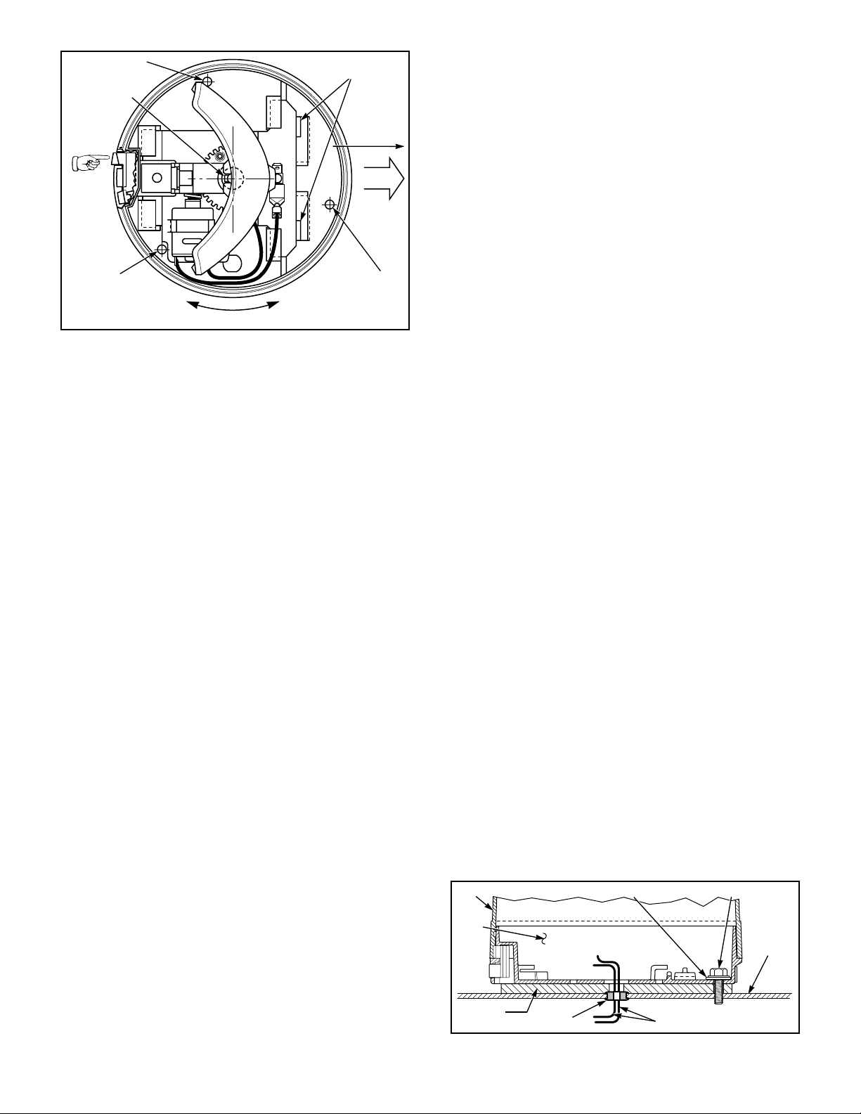
1. Push and hold the dome release button
(located in the plastic base). Turn the dome counterclockwise and lift the dome off the base (see figure 1).
2. Position the vehicle on a level surface.
Select a relatively flat mounting position which provides
sufficient rigidity to support the light and prevent
vibrations caused by the light when the vehicle is in
motion.
CAUTION
Turning reflector by hand may damage motor or
worm gear. To rotate the reflector, connect to an
appropriate power source.
3. Position the light with the dome release
button toward the rear at the selected mounting location.
Page 2
MOUNTING HOLE
DOME
BASE
MOUNTING
SURFACE
MOUNTING
GASKET
#10 FLAT WASHERS (3) #10-32 x 3/4" SCREWS (3)
290A2669-02B
WIRE LEADS
GROMMET
WIRING HOLE
PUSH
TO
RELEASE
DOME
MOUNTING
HOLE
INST ALL REMOVE
TWIST DOME
MECHANISM RELEASE TABS
(PUSH DOWN HERE)
SLIDE TO
REMOVE
FRONT
MOUNTING
HOLE
290A2669-01
Figure 1.
4. Use the base of the light as a template and
scribe three mounting hole drill position marks on the
mounting surface. Also, srcibe one wire routing hole
drill position mark at the center.
mounting surface and leave about 6" of excess wire
above the mounting surface. Also, route a user-supplied
16AWG black wire from a known good vehicle ground
through the grommet in the mounting surface and leave
about 6" of excess wire above the mounting surface.
9. Apply a silicone sealing compound around
the wires and grommet where they pass through the
mounting surface to prevent leakage.
10. Align the holes in the mounting gasket with
the appropriate holes in the base and apply the mounting gasket to the base of the light . Route the wires
through the gasket’s wire routing hole and into the base
of the light.
11. See figure 2. Secure the base to the mounting surface with the three thread-forming screws and
flat washers.
12. Strip approximately 1/4" of insulation from
the end of the red and black wires previously routed into
the base of the light.
CAUTION
To avoid damage when drilling, ensure that
both sides of mounting surface are clear of any
parts or wires.
Also, when drilling any holes, ensure that holes
are drilled only through sheet metal and not
through upholstery.
5. Drill one 1/2" (0.50) hole (wire routing hole)
at the previously scribed center drill position mark.
Drill three 9/64" (0.140) holes (mounting holes) at the
previously scribed outer drill position marks.
6. Install the grommet in the 1/2" wire routing
hole.
WARNING
When installing equipment inside air bag
equipped vehicles, the installer MUST ensure
that the equipment is installed ONLY in areas
recommended by the vehicle manufacturer.
Failure to observe this warning will reduce the
effectiveness of the air bag, damage the air bag,
or potentially damage or dislodge the equipment, causing serious injury or death to you or
others.
13. Crimp the female terminal on the black
wire and attach it to the short black wire with the male
terminal.
14. Crimp the male terminal on the red wire
and attach it to the short red wire with the female
terminal in the light.
CAUTION
Interference with a rotating reflector can
damage the reflector or wires. Ensure that wires
are dressed to prevent any interference.
15. Use the cable tie to dress the wires.
16. Connect the unused terminal of the previously installed switch to one side of a user-supplied
fuseholder. Connect the other side of the fuseholder to
the positive (+) terminal of the vehicle’s battery. Install
an eight (8) ampere fuse in the fuseholder.
17. Replace the dome.
B. Pipe Mount Models.
1. Push and hold the dome release button
(located in the plastic base). Turn the dome counterclockwise and lift the dome off the base (see figure 1).
7. Install a user-supplied switch (current
capacity of at least 8-amperes) at a location which
allows the vehicle and all controls to be operated safely
under all driving conditions.
8. Route a user-supplied 16AWG red wire
from one side of the switch through the grommet in the
Figure 2.
-2-
Page 3

WARNING
When installing equipment inside air bag
equipped vehicles, the installer MUST ensure
that the equipment is installed ONLY in areas
recommended by the vehicle manufacturer.
Failure to observe this warning will reduce the
effectiveness of the air bag, damage the air bag,
or potentially damage or dislodge the equipment, causing serious injury or death to you or
others.
2. Install a user-supplied switch (current
capacity of at least 8-amperes) at a location which
allows the vehicle and all controls to be operated safely
under all driving conditions.
3. Route a user-supplied 16AWG red wire
from one side of the switch through the pipe flange and
into the light. Leave about 6" of excess wire above the
pipe flange. Also, route a user-supplied 16AWG black
wire from a known good vehicle ground through the pipe
flange and into the light. Leave about 6" of excess wire
above the pipe flange.
4. Screw the flange mount light onto the pipe.
Position the light with the dome release button toward
the rear.
it is not intended for use on the exterior of a moving
vehicle.
WARNING
Because vehicle roof construction and driving
conditions vary, Federal does not recommend
driving a vehicle with a magnetically mounted
warning light installed. The light could fly off
the vehicle causing injury or damage. Repair of
damage incurred because of ignoring this
warning shall be the sole responsibility of the
user.
Holding power of magnetic mounting systems is
dependent upon surface finish, surface flatness,
and thickness of the steel mounting surface.
Therefore, to promote proper magnetic mounting:
• Mounting surface and magnets must be
kept clean, dry, and free of foreign particles
that prevent good surface contact.
• Ensure that mounting surface is flat.
• Magnet mounting system should not be
used on vehicles with vinyl tops.
5. Strip approximately 1/4" of insulation from
the end of the red and black wires previously routed into
the base of the light.
6. Crimp the female terminal on the black
wire and attach it to the short black wire with the male
terminal.
7. Crimp the male terminal on the red wire
and attach it to the short red wire with the female
terminal in the light.
CAUTION
Interference with a rotating reflector can
damage the reflector or wires. Ensure that wires
are dressed to prevent any interference.
8. Use the cable tie to dress the wires.
9. Connect the unused terminal of the previously installed switch to one side of a user-supplied
fuseholder. Connect the other side of the fuseholder to
the positive (+) terminal of the vehicle’s battery. Install
an eight (8) ampere fuse in the fuseholder.
10. Replace the dome.
C. Magnetic Mount Models.
Magnetic mounting provides a secure, tempo-
rary mounting method for most installations. However,
• To prevent sliding of light assembly on
mounting surface, quick acceleration and
hard stops should be avoided.
• If the light is to be held directly to the roof
by the magnet, ensure that the power cable
is not under the magnet.
1. Place the light assembly on a level steel
surface. Ensure that the light is placed to promote
maximum coverage and range of the light’s warning
signal.
2. Insert the plug on the end of the power cord
into the cigar lighter socket.
NOTE
When using the vehicle’s cigar lighter socket as
the light’s power source, Federal recommends
replacing the original lighter circuit fuse with
an eight-ampere fuse. After the original fuse has
been replaced, devices requiring more than
eight amperes will cause failure of the lighter
circuit fuse and therefore should not be plugged
into the cigar lighter socket.
If direct connection to the power source (not
utilizing the cigar lighter plug) is desired, a
user-supplied in-line fuseholder and eightampere fuse must be installed in the power
cord’s ribbed (positive) lead.
-3-
Page 4

D. DIN Mount Models.
These models utilize a DIN mounting/connection installation. They are designed for installation on a
24mm tube/female DIN connector.
NOTE
If a user-supplied switch is used, it must have a
current capacity of at least 8-amperes.
1. Loosen the wing nut on the base of the light
assembly.
2. Slide the light assembly onto the 24mm
tube/female DIN connector. Ensure that the connector is
seated in the base of the light.
3. Finger-tighten the wing nut until the base
is snug on the DIN connector.
4. Install a user-supplied fuseholder in the
light’s positive lead and install a 8-ampere fuse in the
fuseholder.
IV. MAINTENANCE.
A. General.
WARNING
Crazing (cracking) of domes will cause reduced
effectiveness of the light. Do not use cleaning
agents (which will cause crazing) such as strong
detergents, solvents, or petroleum products. If
crazing of dome does occur, reliability of light for
emergency signalling purposes may be reduced
until dome is replaced.
CAUTION
Service life of lamp will be shortened if glass
portion is touched. If glass has been handled,
clean carefully with a grease solvent.
1. Rotate the reflector until the C-clip (located
at the base of the lamp) can be removed, and remove the
C-clip by sliding it away from the reflector.
2. See figure 3. Note the lamp’s orientation
and replace the lamp with the straight edge of the
lamp’s base toward the reflector. Replace the 12V lamp
with Part No. 8440A265 and the 24V lamp with Part
No. 8444A151.
C. Mechanism Removal (for servicing).
1. Push and hold the dome release button
(located in the plastic base). Turn the dome counterclockwise and lift the dome off the base (see figure 1).
2. Disconnect power to the light. Disconnect
the red and black leads in the light.
3. See figure 1. Push and hold the mechanism
release tabs.
4. Slide the mechanism over the release tabs
and lift the mechanism out of the base.
5. After servicing, replace the mechanism by
performing the above steps in reverse order.
1. The dome can be cleaned using a nonabrasive, high quality, automotive paste wax and a soft
cloth.
2. On magnetic mount lights, periodically
inspect the magnet for dirt and metal shavings. Clean
the magnet as necessary. Keep the area around the
magnetic mount light free of dirt and metal shavings.
3. Apply a film of light grease to the gears
when necessary.
B. Lamp Replacement.
WARNING
A serious injury may result if lamp is touched
when hot. Always allow lamp to cool before
removing. Halogen lamps are pressurized and if
broken can result in flying glass. Always wear
gloves and eye protection when handling the
lamps.
H-I HALOGEN LAMP
LAMP BASE
ORIENTED PARALLEL
TO GROVES IN
LAMP SOCKET
CONNECTOR
LAMP SOCKET
GROOVES(2)
GEAR AND REFLECTOR
ASSEMBLY
Figure 3.
DO NOT TOUCH
GLASS PORTION
OF LAMP
SLIDE CLIP OVER
LAMP BASE INTO
GROOVES ON
LAMP SOCKET
290A2600-01
-4-
 Loading...