

Page 1
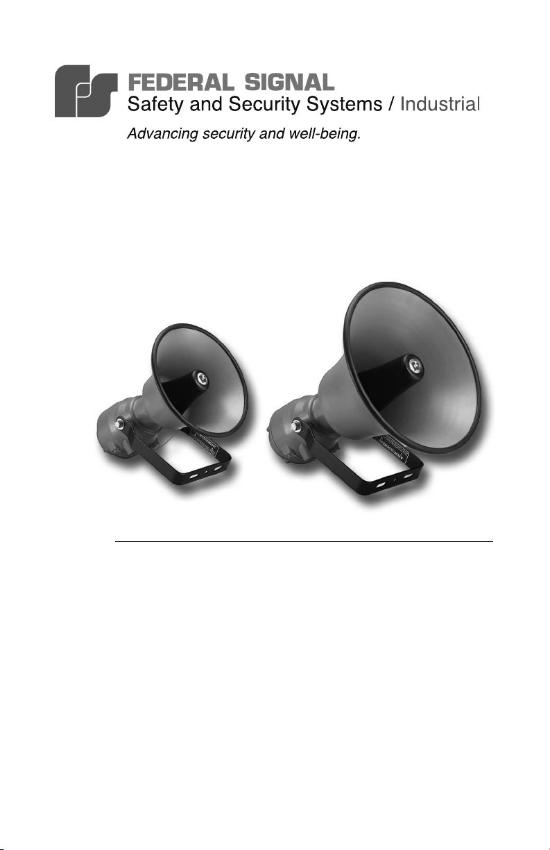
SelecToneTM Models 304X and 314X
Explosion-Proof Amplied Speakers
Installation and
Maintenance Instructions
2562113A
Rev. A1 114
Printed in U.S.A.
français...............page 23
español...............página 45
Page 2

Warranty – Seller warrants all goods for ve years on parts and 2-1/2 years on
labor, under the following conditions and exceptions: Seller warrants that all
goods of Seller's manufacture will conform to any descriptions thereof for specications which are expressly made a part of this sales contract and at the time of
sale by Seller such goods shall be commercially free from defects in material or
workmanship. Seller reserves the right at the Seller’s discretion to “Repair and
Return” or “Replace” any item deemed defective during the warranty period.
This warranty does not cover travel expenses, the cost of specialized equipment
for gaining access to the product, or labor charges for removal and reinstallation of the product. This warranty shall be ineffective and shall not apply to
goods that have been subjected to misuse, neglect, accident, damage, improper
maintenance, or to goods altered or repaired by anyone other than Seller or its
authorized representative, or if ve years have elapsed from the date of shipment
of the goods by Seller with the following exceptions: lamps and strobe tubes are
not covered under this warranty. Outdoor warning sirens and controllers manufactured by Federal Warning Systems are warranteed for two years on parts and
one year on labor. No agent, employee, representative or distributor of Seller has
any authority to bind the Seller to any representation, afrmation, or warranty
concerning the goods and any such representation, afrmation or warranty shall
not be deemed to have become a part of the basics of the sales contract and
shall be unenforceable. THE FOREGOING WARRANTIES ARE EXCLUSIVE
AND IN LIEU OF ALL OTHER WARRANTIES OR MERCHANTABILITY,
FITNESS FOR PURPOSE AND OF ANY OTHER TYPE, WHETHER EXPRESS OR IMPLIED. These warranties shall not apply unless Seller shall be
given reasonable opportunity to investigate all claims for allegedly defective
goods. Upon Seller's instruction a sample only of allegedly defective goods shall
be returned to Seller for its inspection and approval. The basis of all claims for
alleged defects in the goods not discoverable upon reasonable inspection thereof
pursuant to paragraph 8 hereof must be fully explained in writing and received
by Seller within thirty days after Buyer learns of the defect or such claim shall be
deemed waived.
Industrial Systems
2645 Federal Signal Drive • University Park, IL 60484-3167
Tel: 708-534-4756 • Fax: 708-534-4852
Email: elp@federalsignal.com • www.federalsignal-indust.com
Page 3

Models 304X and 314X Explosion-Proof Amplied Speakers
Contents
Safety Message to Installers and Users ............................................... 5
An Overview of the Speakers
Unpacking the Speaker
Mounting the Speaker
Installing the UTM Universal Tone Module
Installing the Speaker Connector Card
Safety Message to Operators
Testing and Operating the Speaker
Safety Message to Maintenance Personnel
Maintaining the Speaker
Ordering Replacement Parts
Returning the Product for Credit
............................................................................ 8
................................................................ 6
.......................................................................... 7
........................................ 11
.............................................. 13
.............................................................. 17
.................................................... 17
....................................... 18
...................................................................... 19
............................................................... 19
........................................................ 20
Tables
Table 1 Model 304X specications .......................................................... 7
Table 2 Model 314X specications .......................................................... 8
Table 3 Tone and Connector Card UL Audibility Ratings ........................8
Table 4 Model 304X replacement parts ................................................20
Table 5 Model 314X replacement parts ................................................20
Figures
Figure 1 Mounting hole locations and dimensions.................................. 9
Figure 2 Dimensions of the Model 304X............................................... 10
Figure 3 Dimensions of the Model 314X............................................... 10
Figure 4 Speaker with cover removed .................................................. 12
Figure 5 Speakers connected to EOL device ....................................... 15
Figure 6 Speakers with supervision relay and connector card ............. 16
3
Page 4

© 2013 Federal Signal Corporation. All rights reserved.
Page 5

Installation and Maintenance Instructions
Safety Message to Installers and Users
People’s lives depend on your safe installation of our products. It is
important to follow all instructions shipped with this product. This
device is to be installed by a trained electrician who is thoroughly
familiar with the National Electrical Code and/or Canadian Electrical
Code and will follow the NEC and/or CEC Guidelines as well as all
local codes. This horn should be considered a part of the warning
system and not the entire warning system.
The selection of the mounting location for this horn, its controls and
the routing of the wiring are to be accomplished under the direction
of the Facilities Engineer and the Safety Engineer. In addition, listed
below are some other important safety instructions and precautions
you should follow:
• Read and understand all instructions before installing, operating,
or maintaining this equipment.
•
Warning–Explosion Hazard – Do not disconnect equipment
unless power has been switched off or the area in known to be
non-hazardous.
• Do not connect this unit to the system when power is on.
• Optimum sound distribution will be severely reduced if any
objects are in front of the horn. You should ensure that the front
of the horn is clear of any obstructions.
• All effective warning horns produce loud sounds which may
cause, in certain situations, permanent hearing loss. The device
should be installed far enough away from potential listeners to
limit their exposure while still maintaining its effectiveness. The
OSHA Code of Federal Regulations 1910.95 Noise Standard
provides guidelines which may be used regarding permissible
noise exposure levels.
• After installation, ensure that all mounting screws, bolts, and
threaded joints are tightened.
Models 304X and 314X Explosion-Proof Amplied Speakers
5
Page 6

Installation and Maintenance Instructions
• Establish a procedure to routinely check the signal system for
proper activation and operation.
• Any maintenance to the unit MUST be performed by a trained
electrician in accordance with NEC Guidelines and local codes.
• Never alter the unit in any manner.
• The nameplate should NOT be obscured, as it contains cautionary
and/or other information of importance to maintenance personnel.
• After installation and completion of initial system test, a program
for periodic testing of this device must be established. Refer to
NFPA 72G, local Fire Codes and the authority having jurisdiction
for this information.
• Provide a copy of these instructions to the Safety Engineer,
operator(s) and maintenance personnel.
• File these instructions in a safe place and refer to them when
maintaining and/or reinstalling the device.
Failure to follow all safety precautions and instructions may result in
property damage, serious injury, or death.
An Overview of the Speakers
The Federal Signal Model 304X and 314X Explosion-Proof
Amplied Speakers are designed to produce crisp, clear tones in
supervised alarm notication systems. Both models are compatible
with re alarm, voice evacuation, suppression supervised control
panels, and power boosters.
These amplied speakers can broadcast tones generated by a Tone
Card installed into the speaker (the plug-in 32-tone UTM) or by a
central tone source in a voice evacuation or paging system. When live
public address or voice messages are required, plug-in Federal Signal
Connector Cards (AM25CK or AM70CK) interface with the Vrms of
the EVAC panel.
6
Models 304X and 314X Explosion-Proof Amplied Speakers
Page 7

Installation and Maintenance Instructions
The speaker cone and projector are constructed of rugged spun
aluminum. The solid-state amplier circuit is protected in a diecast aluminum housing. Dust- and moisture-proof gaskets provide
protection from the elements. All external surfaces are sealed with
gray powder-coat paint. A heavy-duty swivel mount bracket allows
the installer to direct the output effectively.
The rugged construction and high output of the Model 304X and
314X make them ideal for use in harsh environments with high
ambient noise levels. Both models feature an internal gain control for
adjustment to suit the area.
This equipment is suitable for use in Class 1, Division 1, Groups B, C,
D; Class I, Division 2, Groups A, B, C, D or non-hazardous locations
only.
Unpacking the Speaker
After unpacking the horn, examine it for damage that may have
occurred in transit. If the horn has been damaged, do not attempt to
install or operate it. File a claim immediately with the carrier, stating
the extent of the damage. Carefully check all envelopes, shipping
labels, and tags before removing or discarding them. Disposal of all
shipping materials must be carried out in accordance with national
and local codes and standards. If any parts are missing, please call
Federal Signal Customer Support at 708-534-4756 or 877-289-3246.
Table 1 Model 304X specications
Operating Voltage: Regulated 24 Vdc (16 Vdc to 33 Vdc)
Maximum Current: 0.83 A
Standby Current: 0.13 A
Operating Temperature: -40 ºF to 150 ºF (-40 ºC to 66 ºC)
Net Weight: 15.4 lb (7.0 kg)
Shipping Weight: 22.8 lb (10.4 kg)
Dimensions:
Construction:
Models 304X and 314X Explosion-Proof Amplied Speakers
16.3 in D x 17.0 in H x 13.1 in W
414.02 mm D x 431.80 mm H x 332.73 mm W
Aluminum enclosure and adjustable steel
mounting bracket with a powder-coat nish
7
Page 8
Installation and Maintenance Instructions
Table 2 Model 314X specications
Operating Voltage: Regulated 24 Vdc (16 Vdc to 33 Vdc)
Maximum Current: 0.90 A
Standby Current: 0.13 A
Operating Temperature: -40 ºF to 150 ºF (-40 ºC to 66 ºC)
Net Weight: 16.4 lb (7.4 kg)
Shipping Weight: 32.4 lb (14.7 kg)
Dimensions: 19.5 in D x 18.8 in H x 16.7 in W
495.30 mm D x 477.52 mm H x 424.17 mm W
Ingress Protection: IP65 and NEMA 4X Approved
Construction: Aluminum enclosure and adjustable steel
mounting bracket with a powder-coat nish.
Compatible Tone Modules: TM2 or UTM
Compatible Speaker Connector Cards: AM25CK*, AM70CK*,
or 300CKS
*Series A versions of these connector cards are not compatible.
Table 3 Tone and Connector Card UL Audibility Ratings
Rating: UL dB (A) Sound Pressure per UL1480
Speaker: 304X 314X
Audibility Rating*: 91 97
AM25CK: 101 99
AM70CK: 101 99
*Based on TM6, HORN
Mounting the Speaker
The speaker can be mounted on any relatively at surface capable
of supporting the weight of the speaker. Conduit connections can be
made to the 1/2" NPT threaded openings at bottom of the housing
(see Figure 4 on page 12).
To mount the speaker:
Remove the two 1/2"-13 hex-head bolts, at washers, and
1.
lockwashers that secure the mounting bracket to the speaker.
8
Models 304X and 314X Explosion-Proof Amplied Speakers
Page 9
Installation and Maintenance Instructions
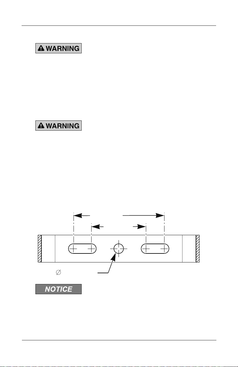
5.0" (127 mm)
0.53" (13.5 mm)
290A5198
2. Disconnect the lanyard from the mounting bracket at the cotter ring.
MOUNTING PRECAUTION — Property damage, serious
injury, or death could occur if an accumulation of water,
snow, dust, etc. resides in the speaker projector, severely
reducing or preventing the operation of this device. Mount
the speaker so the speaker projector is pointed horizontally
or slightly downward.
3. Select the mounting location.
MOUNTING PRECAUTION — Property damage, serious
injury, or death could occur if any objects are in front of
speaker, severely reducing optimum sound distribution. For
maximum effectiveness, ensure that the front of the speaker
is clear of obstructions.
4. See Figure 1. Using the mounting bracket as a template, scribe
drill position marks on the mounting surface.
Figure 1 Mounting hole locations and dimensions
3.0" (76 mm)
+
DRILLING PRECAUTION — Before drilling holes in any
surface, be sure both sides of surface are clear of anything
that could be damaged.
Models 304X and 314X Explosion-Proof Amplied Speakers
9
Page 10
Installation and Maintenance Instructions
290A5201
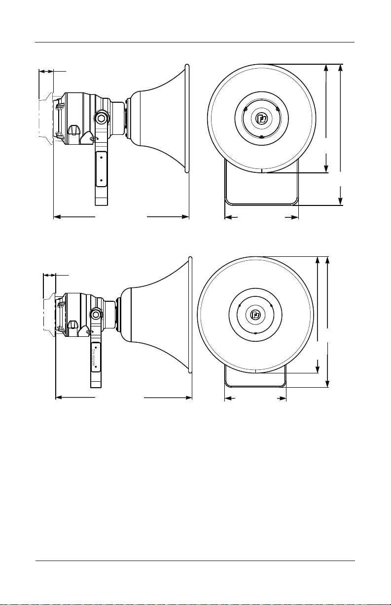
Figure 2 Dimensions of the Model 304X
1.8" (46 mm)
TO REMOVE COVER
13.1"
(333 mm)
WARNING
16.3" (414 mm)
8.9" (226 mm)
17.0"
(432 mm)
290A5200
Figure 3 Dimensions of the Model 314X
1.8" (46 mm)
TO REMOVE COVER
18.8"
(478 mm)
16.7"
WARNING
19.5" (496 mm)
8.9" (226 mm)
(425 mm)
5. Drill holes at the scribed drill-position marks to accommodate the
1/2" diameter bolts.
Secure the bracket to the mounting surface with the 1/2" diameter
6.
hex-head bolts, lockwashers, and hex nuts.
Reattach the speaker to the mounting bracket with the two
7.
1/2"-13 hex-head bolts, at washers, and lockwashers.
Position the speaker to obtain the required sound coverage, then
8.
tighten the bolts securely.
10
Models 304X and 314X Explosion-Proof Amplied Speakers
Page 11
Installation and Maintenance Instructions
9. Reattach the lanyard to the cotter ring and mounting bracket.
Verify that it is securely attached to both the cover and the
mounting bracket.
Route wires through the 1/2" NPT threaded openings into the
10.
SelecTone unit in accordance with national and local electrical
and re codes. Wire size depends upon the operating current
and the distance from the power source.
See the next sections for instructions on installing the speaker
connector card and UTM module, and wiring the speaker.
Installing the UTM Universal Tone Module
MISWIRING/ELECTRICAL SUPERVISION — Property damage,
serious injury, or death could occur if independent conductors
are terminated together; both wires of the same polarity must
be used as two separate connections. NFPA 72 requires that
the wires be terminated independently to provide electrical
supervision of the connection.
SHOCK HAZARD — To avoid electrical shock hazards, do not
connect wires when power is applied. Failure to heed this
warning may cause serious injury or death.
For details, refer to the instructions for the Model UTM Universal
Tone Module, doc. No. 2561101.
To install the UTM module in the speaker:
DO NOT DAMAGE SEALING SURFACES — Property damage,
serious injury, or death could occur if the machined sealing
surfaces are damaged on this product. To maintain the
effectiveness of the explosion-proof enclosure, be careful
to avoid damaging the machined sealing surfaces of cover
and housing.
Models 304X and 314X Explosion-Proof Amplied Speakers
11
Page 12
Installation and Maintenance Instructions
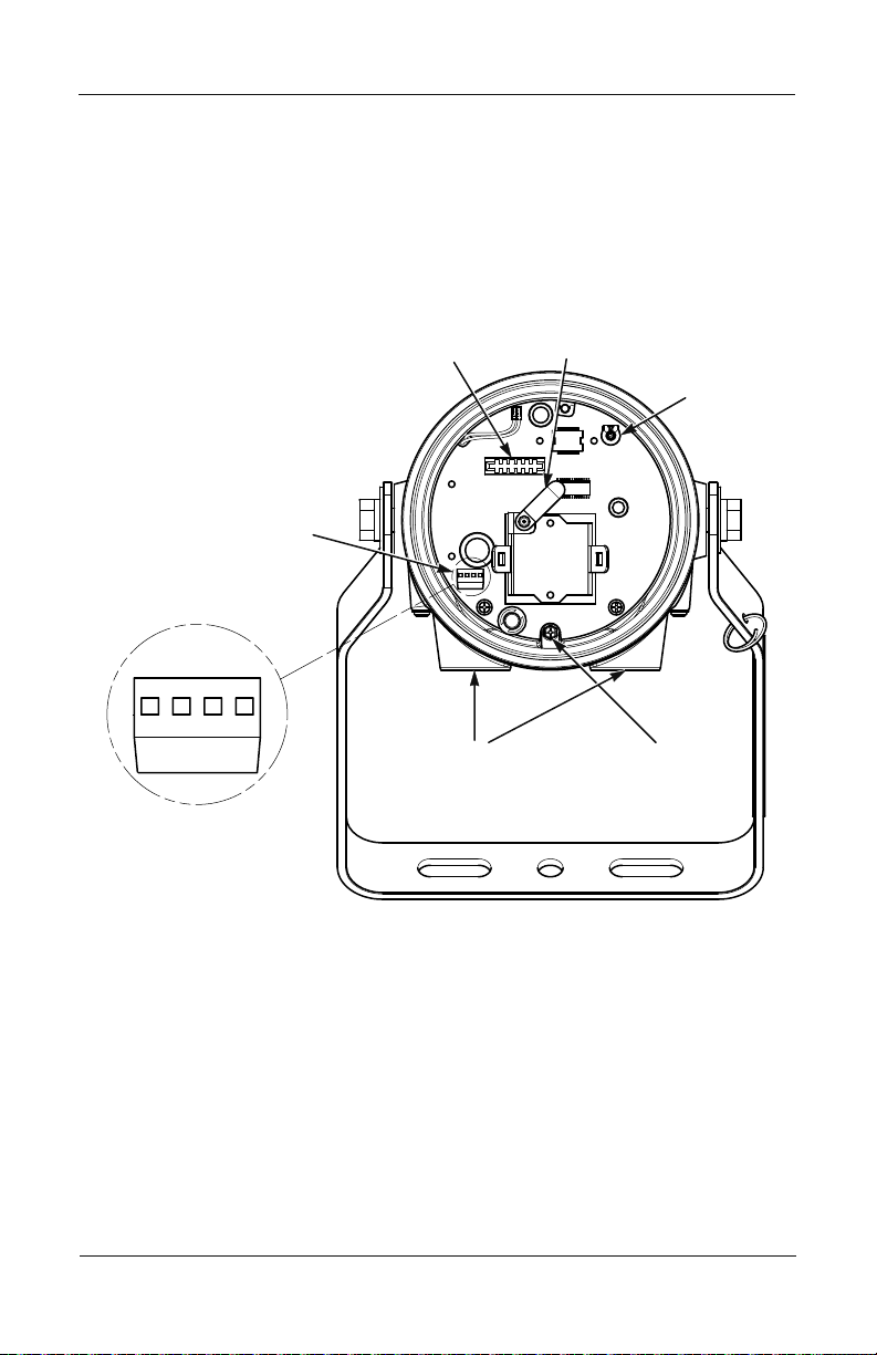
POWER CONNECTOR
DETAIL
1/2" NPT
CONDUIT
ENTRANCES
EARTH
GROUND
POWER
CONNECTOR
SOCKET FOR TONE OR
CONNECTOR CARD
TONE/CONNECTOR
CARD RETAINER
VOLUME
CONTROL
L
(+)
L
(+)N(-)N(-)
1. Loosen and remove the threaded cover by turning it counterclockwise. Allow the cover to hang by the attached lanyard.
Plug the tone card (purchased separately) into the socket as
2.
shown in Figure 4.
Figure 4 Speaker with cover removed
3. Rotate the card retainer into position over the tone card so that it
holds the card in place (Figure 4).
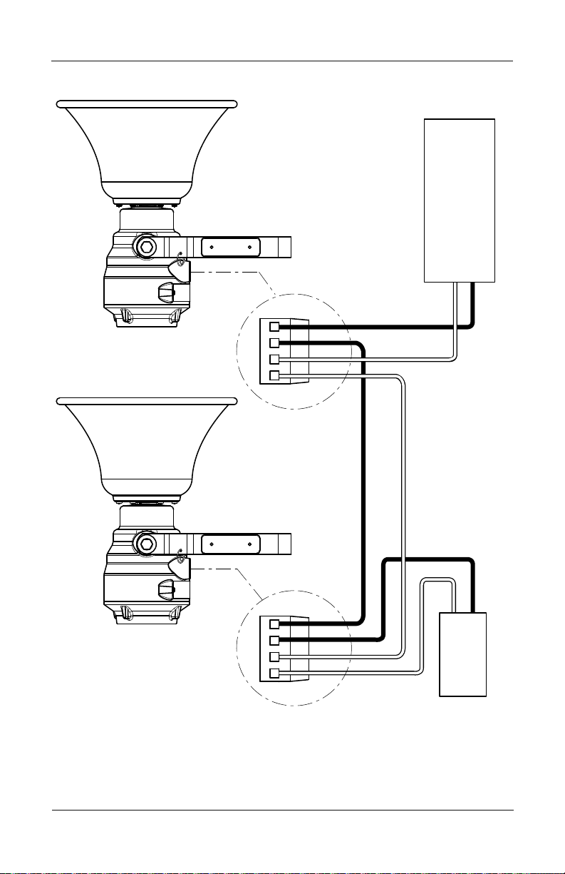
See Figure 5 on page 15 and Figure 6 on page 16. Connect the
4.
positive (+) power-source lead to the terminal block labeled L+.
Connect the negative (–) power-source lead to the terminal block
5.
labeled N–.
Connect the additional positive (L+) and negative (N–) terminal
6.
leads to the next speaker or to an end-of-line device.
12
Models 304X and 314X Explosion-Proof Amplied Speakers
Page 13
Installation and Maintenance Instructions
EXPLOSION HAZARD — Property damage, serious injury, or
death could occur if the housing is not closed properly. To
reduce possibility of explosion, the housing cover must be
kept tight while circuits are energized.
7. Carefully reinstall the housing cover and tighten it until the cover
ange makes contact with the housing.
8.
To secure the cover, tighten the set screw on the cover. Verify that
the mounting bolts are securely tightened.
Installing the Speaker Connector Card
For more details, refer to the instructions for the SelecTone AM25CK
and AM70CK Connector Cards, doc. No. 2561183.
MISWIRING/ELECTRICAL SUPERVISION FAILURE — Property
damage, serious injury, or death could occur if independent
conductors are terminated together; both wires of the same
polarity must be used as two separate connections. NFPA 72
requires that the wires be terminated independently to provide
electrical supervision of the power supply connection and
audio lines.
SHOCK HAZARD — To avoid electrical shock, do not connect
wires when circuits are energized. Failure to heed this warning
may cause serious injury or death.
To install the connector card:
1.
Plug the connector card (purchased separately) into the socket as
shown in Figure 4 on page 12.
2.
Rotate the card retainer into position over the tone card so that it
holds the card in place (Figure 4).
3.
See Figure 5 on page 15 or Figure 6 on page 16. Connect the
positive power-source (+) lead to the terminal labeled L+.
Models 304X and 314X Explosion-Proof Amplied Speakers
13
Page 14

Installation and Maintenance Instructions
4. Connect the negative (–) power-source lead to the negative
terminal labeled
Connect the additional positive (L+) and negative (N –) terminal-
5.
N –.
block leads to the next speaker or to a power supervision relay.
Connect one pair of white leads from the connector card to the
6.
audio output of the re alarm panel.
Connect the other pair of white leads to the connector card in the
7.
next speaker or to a contact on the power supervision relay and
an end of line device.
NOTE: Check with the authority having jurisdiction for the proper
application of the required EOL resistor and power supervision
relay (see Figure 6 on 16).
EXPLOSION HAZARD — Property damage, serious injury, or
death could occur if the housing is not closed properly. To
reduce possibility of explosion, the housing cover must be
kept tight while circuits are energized.
8. Carefully reinstall the housing cover and tighten it until the cover
ange makes contact with the housing.
To secure the cover, tighten the set screw on the cover. Verify that
9.
the mounting bolts are securely tightened.
14
Models 304X and 314X Explosion-Proof Amplied Speakers
Page 15
Installation and Maintenance Instructions
290A5202
Figure 5 Speakers connected to EOL device
WARNING
WARNING
POR EL PROVEEDOR
DISPOSITIVOS DE FINAL DE
DE LA UNIDAD DE CONTROL
LÍNEA (DFL) RECOMENDADO
–
+
–
N
–
N
L
+
L
+
–
N
–
N
L
+
L
+
–
+
ALIMENTACIÓN
24 VCC
Models 304X and 314X Explosion-Proof Amplied Speakers
15
Page 16
Installation and Maintenance Instructions
290A5203
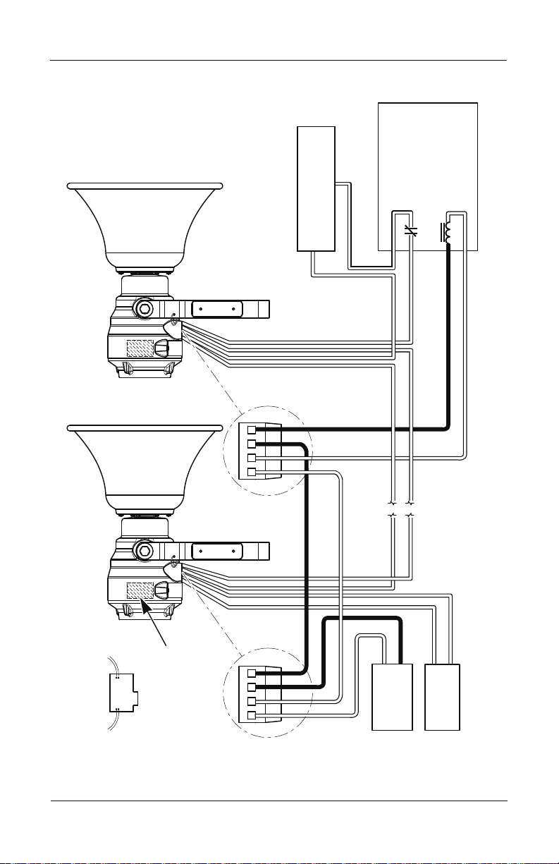
Figure 6 Speakers with supervision relay and connector card
WARNING
WARNING
RECOMMENDED BY
END OF LINE DEVICE
CONTROL UNIT SUPPLIER
–
N
–
N
L
+
+
L
A77-716-02
RELAY MODEL
FOR 24 VDC USE:
POWER SUPERVISION
OR MODEL R64 BY
BY SYSTEM SENSOR,
–
WHT
WHT
WHT
WHT
PRODUCTS
UNITED SECURITY
+
16
–
+
–
N
–
N
L
+
L
+
CARD (25 OR 70 VMRS
INTERNAL CONNECTOR
(SUPPLIED SEPARATELY)
Models 304X and 314X Explosion-Proof Amplied Speakers
POWER
SPEAKER
WHT
WHT
25 OR 70
VRMS AUDIO
Page 17
Installation and Maintenance Instructions
Safety Message to Operators
TESTING/TRAINING PRECAUTIONS — Even if your warning
system is operating properly, it may not be completely effective.
People may not hear or heed your warning signal. You must
recognize this fact and ensure that your warning signal achieves
its intended effect through proper test/training sequences within
your specic application(s).
Testing and Operating the Speaker
SOUND HAZARD — Under certain conditions these devices are
capable of producing sounds loud enough to cause hearing
damage. Adequate hearing protection should be worn if standing
within close proximity to device while testing. Recommendations
in the OSHA Sound Level Standard (29 CFR 1910) should not be
exceeded.
EXPLOSION HAZARD — Property damage, serious injury, or
death could occur if the housing is not closed properly. To
reduce possibility of explosion, the housing cover must be kept
tight while circuits are energized.
After the installation is completed, be sure to test the system to verify
that each amplied speaker operates satisfactorily. If the speaker is too
loud for the location, adjust the volume as described in these steps:
1.
Remove the housing cover and insert a slotted electrician-type
screwdriver into the volume control shown in Figure 4 on page 12.
2. Gently turn the control counter-clockwise to decrease the sound
output to the desired loudness.
3.
Reinstall the housing cover.
After completion of the initial system test, establish a program for
periodic testing of this device. Refer to NFPA 72G, local Fire Codes
and the authority having jurisdiction for this information.
Models 304X and 314X Explosion-Proof Amplied Speakers
17
Page 18

Installation and Maintenance Instructions
Provide a copy of these instructions for the Safety Engineer, system
operator(s) and maintenance personnel.
Safety Message to Maintenance Personnel
Failure to follow all safety precautions and instructions may result in
property damage, serious injury, or death to you or others.
• Read and understand all instructions before performing
maintenance on this unit.
• Do not perform maintenance on this unit when circuits are
energized.
• Do not disconnect the speaker from the system wiring when
circuits are energized.
• Periodic checks should be made to ensure that effectiveness of this
device has not been reduced because speaker has become clogged
with a foreign substance or because objects have been placed in
front of the speaker.
• Any maintenance to this unit MUST be performed by a trained
electrician in accordance with the National Electrical Code,
National Fire Codes, and the local codes.
• Never alter this unit in any manner. Safety in hazardous locations
may be jeopardized if additional openings or alterations are made
to this device.
• The nameplates, which contain cautionary or other information of
importance to maintenance personnel, should not be obscured if
exterior of device is painted.
• WARNING: Explosion Hazard — Substitution of components
may impair suitability for Class I, Division 2 and Class I,
Zone 2.
Failure to follow all safety precautions and instructions may result in
property damage, serious injury, or death.
18
Models 304X and 314X Explosion-Proof Amplied Speakers
Page 19

Installation and Maintenance Instructions
Maintaining the Speaker
UNAUTHORIZED REPAIR/SERVICING — Unauthorized
repair/servicing of the speaker may result in degradation of
performance and/or property damage, serious injury, or death
to you or others. If a malfunctioning unit is encountered, do not
attempt any eld repair/retrot of parts.
EXPLOSION HAZARD — Property damage, serious injury or
death could occur if this product’s machined sealing surfaces
are damaged. To maintain the effectiveness of the explosionproof enclosure, use caution to avoid damaging the machined
surfaces.
Periodically check this device to verify that there are no foreign
substances in, or in front of, the speaker which will reduce its
effectiveness.
Testing should be periodically performed. Refer to NFPA 72G, local
Fire Codes and the authority having jurisdiction for information.
If a volume adjustment or other repair is needed, be sure to refer to
the “Safety Message For Maintenance Personnel” on page 18 before
proceeding.
Ordering Replacement Parts
Typical spare parts are listed in Tables 4 and 5 on page 20. Due
to certication, certain component parts are not available for eld
replacement. Units with this type of damage must be either replaced
entirely or returned to Federal Signal for service.
To order accessories and replacement parts, call Federal Signal
Customer Support at 708-534-4756 or 877-289-3246
Models 304X and 314X Explosion-Proof Amplied Speakers
19
Page 20
Installation and Maintenance Instructions
Models 304X and 314X Explosion-Proof Amplied Speakers
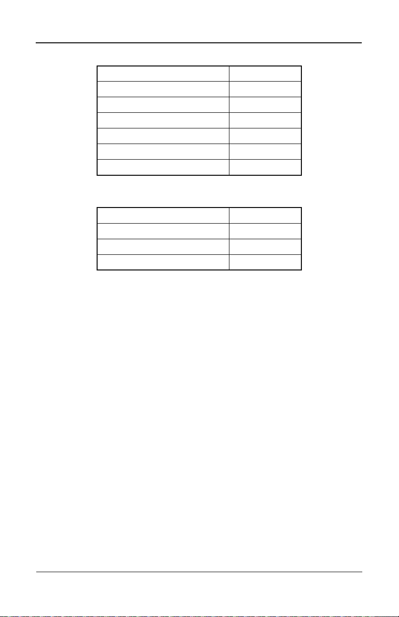
Table 4 Model 304X replacement parts
Description Part Number
Amplier Assembly K2005355-01
Horn Assembly K8593100
Driver Assembly K8593097
Cover Assembly K8593098
Mounting Bracket Assembly K8593071
4-Position Connector K140340
Table 5 Model 314X replacement parts
Description Part Number
Amplier Assembly K2005355-01
Horn Assembly K8593101
4-Position Connector K140340
Returning the Product for Credit
Product returns for credit require a return authorization from your
local distributor prior to returning the product to Federal Signal.
Please contact your distributor for assistance.
A product is qualied to be returned for credit when the following
conditions are met:
• Product is resalable and in the original cartons
• Product has not been previously installed
• Product is the current revision
• Product has not been previously repaired
• Product is a standard product
• Product is not a service part
All returns are subject to a re-stock fee.
20
Page 21

Installation and Maintenance Instructions
Models 304X and 314X Explosion-Proof Amplied Speakers
Defective products that are returned within the warranty period will
be repaired or replaced at Federal Signal’s sole discretion. Defective
products do not include those products with lamp failure.
Circumstances other than those listed above will be addressed on a
case-by-case basis.
21
Page 22

Industrial Systems
2645 Federal Signal Drive • University Park, IL 60484-3167
Tel: 708-534-4756 • Fax: 708-534-4852
Email: elp@federalsignal.com • www.federalsignal-indust.com
22
Page 23

Modèles SelecTone
MD
304X et 314X
antidéagrant haut-parleurs ampliés
Instructions d’installation
et d’entretien
2562113A
Rev. A1 114
Imprimé aux Etats-Unis
23
Page 24

ans
G
A
E
I
T
R
N
A
Garantie – Tous les produits du vendeur sont couverts par une garantie de cinq ans pour
les pièces et de deux ans et demi pour la main-d’œuvre selon les conditions et exceptions
suivantes : Le vendeur garantit que tous les produits qu’il fabrique seront conformes
aux descriptions correspondant aux spécications qui font expressément partie de ce
contrat de vente et qu’au moment de la vente par le vendeur, de tels produits devront
être exempts de défauts de matériel ou de fabrication. Le vendeur se réserve le droit, à sa
discrétion, de « Réparer et retourner » ou de « Remplacer » tout article jugé défectueux
durant la période de garantie. Cette garantie ne couvre pas les frais de voyage, le coût
de l’équipement spécialisé pour avoir accès au produit ou les frais de main-d’œuvre
liés à l’enlèvement et à la réinstallation du produit. Cette garantie sera inopérante et
ne s’appliquera pas aux produits qui ont subi un mauvais usage, une négligence, un
accident, des dommages ou un entretien inapproprié, ou aux produits modiés ou réparés
par quelqu’un d’autre que le vendeur ou son représentant autorisé, ou si cinq ans se
sont écoulés depuis la date de l’envoi des produits par le vendeur avec les exceptions
suivantes : les lampes et les tubes stroboscopiques ne sont pas couverts par cette garantie.
Les sirènes d’avertissement extérieures et les appareils de contrôle fabriqués par Federal
Warning Systems sont couverts par une garantie deux ans sur les pièces et d’un an sur la
main-d’œuvre. Aucun agent, employé, représentant ou distributeur du vendeur n’a autorité pour lier celui-ci à une représentation, afrmation, ou garantie relative aux produits
et une telle représentation, afrmation, ou garantie ne pourra pas être considérée comme
faisant partie des généralités du contrat de vente et sera inexécutable. LES GARANTIES
CI-DESSUS SONT EXCLUSIVES ET REMPLACENT TOUTES LES AUTRES
GARANTIES DE QUALITÉ MARCHANDE, DE COMPATIBILITÉ À UN USAGE
PARTICULIER OU D’UN AUTRE TYPE, QU’ELLES SOIENT EXPRESSES OU
IMPLICITES. Ces garanties ne s’appliqueront pas si le vendeur ne se voit pas aménager
la possibilité raisonnable d’enquêter sur toutes les réclamations de produits présumés défectueux. À la demande du vendeur, un seul échantillon des produits présumés défectueux
lui sera renvoyé pour inspection et approbation. Le fondement de toutes les réclamations
liées à des défauts présumés dans les produits qui ne peuvent être découverts sans une
inspection raisonnable en vertu du paragraphe 8 des présentes, doit être entièrement
expliqué par écrit et reçu par le vendeur dans les trente jours suivant la découverte du
défaut par l’acheteur. À défaut, une telle réclamation sera considérée comme nulle.
Industrial Systems
2645 Federal Signal Drive • University Park, IL 60484-3167
Téléphone: 708-534-4756 • Fax: 708-534-4852
Email: elp@federalsignal.com • www.federalsignal-indust.com • www.fs-isys.com
24
Page 25

Modèles 304X et 314X antidéagrant haut-parleurs ampliés
Contenu
Messages de sécurité destinés aux installateurs ............................. 27
Présentation des haut-parleurs........................................................... 28
Déballage de le haut-parleur amplié
Fixation du haut-parleur ...................................................................... 31
Installation du module de tonalité UTM Universal ............................ 34
Installation de carte de connecteurs .................................................. 36
Message de sécurité destiné aux opérateurs .................................... 40
Tester et utiliser le haut-parleur .......................................................... 40
Message de sécurité destiné aux personnel d’entretien .................. 41
Maintenir le haut-parleur amplié ....................................................... 42
Commande de pièces de rechange .................................................... 43
Réparation et assistance technique ................................................... 43
Retour du produit et avoir ................................................................... 44
................................................. 29
Tables
Tableau 1 Caractéristiques techniques du modèle 304X ...................... 30
Tableau 2 Caractéristiques techniques du modèle 314X ...................... 30
Tableau 3 Classement d’audibilité UL des AM25CK et AM70CK.......... 31
Tableau 4 Pièces de rechange pour le modèle 304X ........................... 43
Tableau 5 Pièces de rechange pour le modèle 314X ........................... 43
Figures
Illustration 1 Dimensions et les trous de montage ............................... 32
Illustration 2 Dimensions du modèle 304X .......................................... 33
Illustration 3 Dimensions du modèle 314X .......................................... 33
Illustration 4 Haut-parleur amplié avec couvercle retiré..................... 35
Illustration 5 Parleurs connectés à un dispositif de n de ligne ........... 38
Illustration 6 Connexions à relais et la carte de deconnecteurs .......... 39
25
Page 26

© 2013 Federal Signal Corporation. Tous droits réservés.
Page 27

IInstructions d’installation et d’entretien
AVERTISSEMENT
Messages de sécurité destinés aux installateurs
L’installation sécurisée de nos produits permet d’éviter de mettre
en danger des vies humaines. Il est important de respecter toutes les
consignes jointes à ce produit au moment de l’expédition. Cet appareil
doit être installé par un électricien qualié qui maîtrise parfaitement
le Code national d’électricité et/ou le Code d’électricité canadien et
qui respectera les directives CNE et/ou CCE ainsi que tous les codes
locaux. Ce haut-parleur amplié doit être considéré comme une partie
du système d’avertissement et non comme l’intégralité de celui-ci.
Le choix du lieu de montage de cet avertisseur sonore, de ses
commandes et du passage des câbles doit être effectué sous la
direction de l’ingénieur responsable des installations et de l’ingénieur
responsable de la sécurité. Voici par ailleurs une liste complémentaire
d’instructions et de précautions de sécurité importantes à respecter :
• Lire et comprendre toutes les instructions avant d’installer,
d’utiliser ou d’assurer la maintenance de cet appareil.
•
Avertissement : -- Risque d’explosion ‒ Ne débrancher le haut-
parleur amplié que si le circuit est hors tension, ou qu’il n’y a
pas de concentrations de produits inammables dans la zone.
• Ne pas connecter ce dispositif au système lorsque ce dernier est
sous tension.
• Pour une diffusion optimale du son, veiller à installer l’appareil à
un endroit où la trajectoire du son ne rencontre aucun obstacle.
• Tous les haut-parleurs d’avertissement efcaces produisent
des sons puissants qui, dans certains cas, peuvent entraîner une
perte auditive irréversible. Prendre les précautions appropriées,
comme l’utilisation d’une protection acoustique. Respecter les
recommandations de la norme OSHA sur le niveau sonore (29
CFR 1910).
• Après l’installation, s’assurer que tous les boulons et joints letés
sont bien serrés.
Modèles 304X et 314X antidéagrant haut-parleurs ampliés
27
Page 28

Instructions d’installation et d’entretien
• Dénir une procédure de vérication régulière de l’activation et
du bon fonctionnement du système de signalisation.
• Tout entretien de cet appareil DOIT être effectué par un électricien
formé conformément aux directives du CNE, ainsi qu’aux codes
locaux.
• Ne jamais modier cet appareil de quelque façon que ce soit.
• La plaque signalétique, qui comprend des informations de
mise en garde et/ou d’autres informations importantes pour le
personnel de maintenance, ne doit PAS être masquée. .
• Après l’installation et la réalisation du test initial du système,
un programme de tests périodiques de l’appareil doit être établi.
Se reporter au guide NFPA 72G, aux codes de prévention des
incendies locaux et à l’autorité compétente concernant ces
informations.
• Fournir une copie de ce manuel d’instructions à l’ingénieur
responsable de la sécurité, à l’(aux) opérateur(s) et au personnel
d’entretien.
• Conserver ces instructions dans un endroit sûr et s’y reporter
pour l’entretien et/ou la réinstallation du dispositif.
Le non-respect de l’ensemble des mesures et consignes de sécurité
peut entraîner des dommages matériels, ou des blessures graves voire
mortelles.
Présentation des haut-parleurs
Les modèles 304X et 314X de haut-parleurs ampliés antidéagrants
de Federal Signal sont conçus pour produire des tonalités claires dans
les systèmes supervisés de notication d’alarmes. Les deux modèles
sont compatibles avec les panneaux de contrôle supervisés d’alarme
incendie, d’instructions vocales d’évacuation et de suppression, ainsi
qu’avec les amplicateurs de puissance.
Ces haut-parleurs ampliés permettent de diffuser des tonalités
générées par une carte de tonalité installée dans le haut-parleur
Modèles 304X et 314X antidéagrant haut-parleurs ampliés
28
Page 29

IInstructions d’installation et d’entretien
(le module enchable 32 tonalités UTM) ou par une source de tonalité
centrale dans un système d’instructions vocales d’évacuation ou de
téléavertissement. S’il est nécessaire de s’adresser directement au
public ou de diffuser des messages vocaux, les cartes de connecteurs
enchables (AM25CK ou AM70CK) s’interfacent avec la valeur
efcace de la tension du panneau EVAC.
Le cône diffuseur et le cornet du projecteur sont en aluminium
repoussé robuste. Le circuit de l’amplicateur à semi-conducteurs est
protégé par un boîtier en aluminium coulé sous pression. Des joints
d’étanchéité à la poussière et à l’humidité protègent des éléments.
Toutes les surfaces externes sont étanchéiées avec de la peinture
grise en poudre. Un support de xation pivotant robuste permet à
l’installateur d’orienter efcacement la sortie.
La conception renforcée et la sortie puissante des modèles 304X et
314X en font un appareil idéal dans les environnements difciles où
le niveau sonore ambiant est élevé. Les deux modèles permettent un
contrôle du gain interne an de régler l’appareil en fonction de la
zone.
Cet appareil convient pour une utilisation de classe I, division 1,
groupes B, C, D ; classe I, division 2, groupes A, B, C, D, ou dans les
zones non dangereuses uniquement.
Déballage de le haut-parleur amplié
Après avoir déballé le haut-parleur amplié, soigneusement vérier
s’il a été endommagé lors du transport. S’il a été endommagé, ne pas
tenter de l’installer ou de le faire fonctionner. Déposer immédiatement
une réclamation auprès du transporteur, déclarant l’étendue des
dommages. Examiner soigneusement toutes les enveloppes, étiquettes
d’expédition et autres étiquettes avant de les retirer ou de les détruire.
La mise au rebut de tout matériel d’expédition doit être effectuée
conformément aux normes et codes locaux et nationaux. S’il manque
des pièces, appeler l’assistance clientèle de Federal Signal au
708 534 4756 ou au 877 289 3246.
Modèles 304X et 314X antidéagrant haut-parleurs ampliés
29
Page 30

Instructions d’installation et d’entretien
Tableau 1 Caractéristiques techniques du modèle 304X
Tension de
fonctionnement :
Intensité : 0,83 A max.
Courant de veille : 0,13 A
Température de
fonctionnement :
Poids net : 7,0 kg (15,4 livres)
Poids à l’expédition : 10,4 kg (22,8 livres)
Dimensions : 414 mm (16,3 pouces) de long x 432 mm
Tableau 2 Caractéristiques techniques du modèle 314X
Tension de
fonctionnement :
Intensité : 0,90 A max.
Courant de veille : 0,13 A
Température de
fonctionnement :
Poids net : 7,4 kg (16,4 livres)
Poids à l’expédition : 14,7 kg (32,41 livres)
Dimensions : 496 mm (19,5 pouces) de long x 478 mm
Indice de protection : IP65 et NEMA 4X approuvé
24 V c.c. régulée (de 16 V c.c. à 33 V c.c.)
-40 ºC à 66 ºC
(17,0 pouces) de haut x 333 mm
(13,1 pouces) de diamètre.
24 V c.c. régulée (de 16 V c.c. à 33 V c.c.)
-40 ºC à 66 ºC
(18,8 pouces) de haut x 425 mm
(16,7 pouces) de diamètre.
Modules de tonalité compatibles : TM2 ou UTM
Cartes compatibles de connecteurs pour haut-parleurs : AM25CK*,
AM70CK*, ou 300CKS
* - les versions de la série A de ces cartes de connecteurs ne sont pas
compatibles
Modèles 304X et 314X antidéagrant haut-parleurs ampliés
30
Page 31

IInstructions d’installation et d’entretien
Tableau 3 Classement d’audibilité UL des AM25CK et AM70CK
Classement :
Haut-parleur :
Classement
d’audibilité* :
AM25CK : 101 99
AM70CK : 101 99
*
- Basée sur TM6, HORN (klaxon)
Pression acoustique en dB (A)
conformément au classement UL1480
304X 314X
91 97
Fixation du haut-parleur
Le haut-parleur peut être xé sur toute surface relativement plane
capable de supporter son poids. Les conduits de câbles peuvent être
raccordés aux ouvertures taraudées NPT de 1/2 po à la base du boîtier
(voir illustration 4, page 35).
Pour xer le haut-parleur :
Retirer les deux boulons à tête hexagonale de 1/2"-13, les
1.
rondelles plates et les rondelles de blocage qui xent le support
à l’unité.
Débrancher le cordon du support de xation au niveau de l’anneau
2.
à goupille.
AVERTISSEMENT
PRÉCAUTION DE FIXATION — Des dommages matériels
et des blessures graves voire mortelles peuvent être
occasionnés par l’accumulation d’eau, de neige, de
poussière etc. à l’intérieur du cornet du haut-parleur, ce
qui risque de sérieusement compromettre, voire empêcher,
l’utilisation de l’appareil. Fixer le dispositif de sorte que le
cornet du haut-parleur soit à l’horizontale ou légèrement
orienté vers le bas.
3. Choisir l’emplacement du montage.
Modèles 304X et 314X antidéagrant haut-parleurs ampliés
31
Page 32

Instructions d’installation et d’entretien
127 mm (5,0 pouce)
AVERTISSEMENT
PRÉCAUTION DE FIXATION — Des dommages matériels
et des blessures graves voire mortelles peuvent être
occasionnés par la présence d’objets devant le haut-parleur,
ce qui risque sérieusement de compromettre une diffusion
optimale du son. Pour une efcacité maximale, s’assurer de
l’absence d’obstacles devant le haut-parleur.
4. Voir illustration 1. À l’aide du support de xation en guise de
gabarit, marquer la position des trous à percer sur la surface de
montage.
Illustration 1 Dimensions et les trous de montage
76 mm
(3,0 pouce)
+
13,5 mm
(0,53 pouce)
290A7676
32
PRÉCAUTION DE FORAGE — Avant de percer des trous
sur toute surface, s’assurer que les deux côtés de la
surface sont dégagés et de l’absence d’objet pouvant être
endommagé.
Modèles 304X et 314X antidéagrant haut-parleurs ampliés
Page 33

Illustration 2 Dimensions du modèle 304X
290A7677
8,9 pouce
18,8 pouce
46mm (1,8pouce)
POUR RETIRER
LE COUVERCLE
IInstructions d’installation et d’entretien
333 mm
13,1
WARNING
414 mm (16.3 pouce)
226 mm
(8,9 pouce)
432 mm
17,0 pouce
Illustration 3 Dimensions du modèle 314X
46 mm (1,8 pouce)
POUR RETIRER
LE COUVERCLE
478 mm
425 mm
WARNING
496 mm (19,5")
226 mm
(16,7 pouce)
290A7678
5. Percer des trous aux emplacements marqués précédemment. Ils
doivent pouvoir accueillir des boulons de ½ pouce de diamètre.
6. Fixer le support à la surface de montage avec des boulons à tête
hexagonale de 1/2 pouce de diamètre, des rondelles de blocage
et des écrous hexagonaux.
Rexer le haut-parleur sur son support avec les deux boulons à
7.
tête hexagonale de 1/2"-13, les rondelles plates et les rondelles
de blocage retirés auparavant.
Modèles 304X et 314X antidéagrant haut-parleurs ampliés
33
Page 34

Instructions d’installation et d’entretien
AVERTISSEMENT
AVERTISSEMENT
8. Placer le haut-parleur de façon à obtenir la couverture sonore
voulue, puis serrer fermement ces boulons.
Rexer le cordon sur l’anneau à goupille et le support de xation.
9.
Vérier qu’il est bien xé à la fois au couvercle et au support de
xation.
Passer les ls par les ouvertures taraudées NPT 1/2 po dans
10.
l’unité SelecTone conformément aux codes électriques et de
prévention des incendies nationaux et locaux. La section du
l dépend du courant de fonctionnement et de la distance par
rapport à la source d’alimentation.
Voir les sections suivantes pour obtenir des instructions pour
l’installation de la carte connecteur haut-parleur et le module de
l’UTM et câblage de l’orateur.
Installation du module de tonalité UTM Universal
CÂBLAGE INCORRECT/SURVEILLANCE ÉLECTRIQUE — Il
existe un risque de dommages matériels et de blessures
graves voire mortelles si des conducteurs indépendants ont
les mêmes terminaisons ; les ls de même polarité doivent
être utilisés comme deux branchements distincts. Le guide
NFPA 72 impose que les ls aient une terminaison indépendante
an de permettre la surveillance électrique de la connexion
d’alimentation et des lignes audio.
RISQUE D’ÉLECTROCUTION — An d’éviter les chocs
électriques, ne pas brancher de ls tant que les circuits sont sous
tension. Le non-respect de cet avertissement peut entraîner des
blessures graves ou la mort.
Pour plus de détails, reportez-vous aux instructions pour le modèle
UTM universal module de sons, doc. N ° 2561101.
Modèles 304X et 314X antidéagrant haut-parleurs ampliés
34
Page 35

IInstructions d’installation et d’entretien
DÉTAIL DU CONNECTEUR
D'ALIMENTATION
ENTRÉES DE
CONDUIT 1/2" NPT
MISE À LA TERRE
CONNECTEUR
D'ALIMENTATION
DISPOSITIF DE RETENUE
DE CARTE DE TONALITÉ/
DE CONNECTEURS
PRISE DE CARTE DE TONALITÉ
OU CARTE DE CONNECTEURS
CONTRÔLE
DU VOLUME
L
(+)
L
(+)N(-)N(-)
Pour installer le module UTM dans le haut-parleur :
AVERTISSEMENT
RISQUE D’EXPLOSION — Des dommages matériels et des
blessures graves voire mortelles peuvent survenir si les
surfaces d’étanchéité usinées sont endommagées sur ce
produit. Pour conserver l’efcacité du coffret antidéagrant,
veiller à ne pas endommager les surfaces d’étanchéité usinées
du couvercle et du boîtier.
1. Dévisser le couvercle leté dans le sens inverse des aiguilles d’une
montre et le retirer. Laisser pendre le couvercle par le cordon.
2.
Insérer la carte de tonalité (achetée séparément) dans la prise
comme indiqué dans l’illustration 4.
3. Pivoter le dispositif de retenue de sorte à maintenir la carte en place.
Illustration 4 Haut-parleur amplié avec couvercle retiré
Modèles 304X et 314X antidéagrant haut-parleurs ampliés
35
Page 36

Instructions d’installation et d’entretien
4. Voir l’illustration 5, page 38 et l’illustration 6, page 39. Raccorder
le l positif (+) de la source d’alimentation à la borne “L+.”
Raccorder le l négatif (–) de la source d’alimentation à la borne
5.
“N –.”
Raccorder les bornes (L+) et (N–) supplémentaires à l’unité
6.
suivante ou à un dispositif de n de ligne (DFL).
AVERTISSEMENT
RISQUE D’EXPLOSION — Des dommages matériels et des
blessures graves voire mortelles peuvent survenir si le
boîtier n’est pas correctement fermé. Pour limiter le risque
d’explosion, le couvercle du boîtier doit rester parfaitement
fermé lorsque les circuits sont mis sous tension.
7. Réinstaller soigneusement le couvercle du boîtier et serrer
jusqu’à ce que la bride du couvercle entre en contact avec le
boîtier.
Serrer la vis sans tête sur le couvercle pour le sécuriser. Vérier
8.
que les boulons de xation ont été serrés fermement.
Installation de carte de connecteurs
Pour plus de détails, reportez-vous aux instructions de la SelecTone
AM25CK et AM70CK cartes connecteur, doc. N ° 2561183.
AVERTISSEMENT
CÂBLAGE INCORRECT/SURVEILLANCE ÉLECTRIQUE — Il
existe un risque de dommages matériels et de blessures
graves voire mortelles si des conducteurs indépendants ont
les mêmes terminaisons ; les ls de même polarité doivent
être utilisés comme deux branchements distincts. Le guide
NFPA 72 impose que les ls aient une terminaison indépendante
an de permettre la surveillance électrique de la connexion
d’alimentation et des lignes audio.
Modèles 304X et 314X antidéagrant haut-parleurs ampliés
36
Page 37

IInstructions d’installation et d’entretien
AVERTISSEMENT
RISQUE D’ÉLECTROCUTION — An d’éviter les chocs
électriques, ne pas brancher de ls tant que les circuits sont sous
tension. Le non-respect de cet avertissement peut entraîner des
blessures graves ou la mort.
Pour installer la carte de connecteurs :
Insérer la carte de connecteurs (achetée séparément) dans la prise
1.
comme indiqué dans l’illustration 4, page 35.
Pivoter le dispositif de retenue de sorte à maintenir la carte en
2.
place (illustration 4).
Voir l’illustration 5, page 38 ou l’illustration 6, page 39. Raccorder
3.
le l positif (+) de la source d’alimentation à la borne “L+.”
Raccorder le l négatif (–) de la source d’alimentation à la borne
4.
“N –.”
Raccorder les bornes (L+) et (N –) supplémentaires à l’unité
5.
suivante ou à un relais de surveillance de l’alimentation.
Connecter une paire de ls blancs de la carte de connecteurs à la
6.
sortie audio du panneau d’alarme incendie.
Connecter l’autre paire de ls blancs à la carte de connecteurs
7.
de l’unité suivante ou à un contact du relais de surveillance de
l’alimentation et à un appareil de n de ligne.
NOTE: Vérier auprès de l’autorité compétente que la résistance
de n de ligne et le relais de surveillance de l’alimentation requis
sont correctement utilisés (voir illustration 6, page 39).
AVERTISSEMENT
RISQUE D’EXPLOSION — Des dommages matériels et des
blessures graves voire mortelles peuvent survenir si le
boîtier n’est pas correctement fermé. Pour limiter le risque
d’explosion, le couvercle du boîtier doit rester parfaitement
fermé lorsque les circuits sont mis sous tension.
Modèles 304X et 314X antidéagrant haut-parleurs ampliés
37
Page 38

Instructions d’installation et d’entretien
290A7680
8. Réinstaller soigneusement le couvercle du boîtier et serrer
jusqu’à ce que la bride du couvercle entre en contact avec le
boîtier.
Serrer la vis sans tête sur le couvercle pour le sécuriser. Vérier
9.
que les boulons de xation ont été serrés fermement.
Illustration 5 Parleurs connectés à un dispositif de n de ligne
WARNING
–
N
–
N
L
+
L
+
FOURNISSEUR DE
APPAREIL DE FIN DE LIGNE
(DFL) RECOMMANDÉ PAR LE
–
+
L'UNITÉ DE CONTRÔLE
38
WARNING
–
N
–
N
L
+
L
+
Modèles 304X et 314X antidéagrant haut-parleurs ampliés
+
–
24 V c.c.
ALIMENTATION
Page 39

IInstructions d’installation et d’entretien
290A7681
Illustration 6 Connexions à relais et la carte de deconnecteurs
POUR 24 V c.c :
SUPERVISION DE
PUISSANCE RELAIS
BLANC
BLANC
BLANC
BLANC
MODÈLE A77-716-02
FOURNISSEUR DE
L'UNITÉ DE CONTRÔLE
APPAREIL DE FIN DE LIGNE
(DFL) RECOMMANDÉ PAR LE
WARNING
–
N
–
N
L
+
+
L
WARNING
PRODUCTS
UNITED SECURITY
OU MODÈLE R64 DE
DE SYSTEM SENSOR,
+
–
–
CONNECTEURS
CARTE INTERNE DE
FOURNI SÉPARÉMENT
(VMRS 25 OU 70 VMRS)
+
–
N
–
N
L
+
L
+
ALIMENTATION
POUR HAUT-
BLANC
PARLEUR
BLANC
AUDIO
25 OU 70 VRMS
Modèles 304X et 314X antidéagrant haut-parleurs ampliés
39
Page 40

Instructions d’installation et d’entretien
Message de sécurité destiné aux opérateurs
AVERTISSEMENT
PRÉCAUTIONS D’ESSAI / FORMATION — Même si votre système
de signalisation fonctionne correctement, son efcacité n’est
peut-être pas optimale. Les personnes concernées peuvent ne
pas entendre ou prêter attention à votre signal d’avertissement.
Vous devez en tenir compte et vous assurer que votre signal
d’avertissement produise l’effet escompté par le biais de
tests/sessions de formation appropriés dans le cadre de vos
applications spéciques.
Tester et utiliser le haut-parleur
AVERTISSEMENT
RISQUE DE BRUIT FORT — Tous les haut-parleurs
d’avertissement efcaces produisent des sons puissants
qui, dans certains cas, peuvent entraîner une perte auditive
irréversible. Prendre les précautions appropriées, comme
l’utilisation d’une protection acoustique. Respecter les
recommandations de la norme OSHA sur le niveau sonore
(29 CFR 1910).
AVERTISSEMENT
RISQUE D’EXPLOSION — Des dommages matériels et des
blessures graves voire mortelles peuvent survenir si le boîtier
n’est pas correctement fermé. Pour limiter le risque d’explosion,
le couvercle du boîtier doit rester parfaitement fermé lorsque les
circuits sont mis sous tension
Une fois l’installation terminée, tester le système pour vérier que
chaque haut-parleur amplié fonctionne correctement. Si l’unité
est trop bruyante pour son emplacement, de régler le volume en
procédant comme suit :
1. Retirer le couvercle du boîtier et insérer un tournevis plat de
type électricien dans la commande de volume présentée dans
l’illustration 4, page 35.
Modèles 304X et 314X antidéagrant haut-parleurs ampliés
40
Page 41

IInstructions d’installation et d’entretien
AVERTISSEMENT
2. Tourner doucement la commande dans le sens inverse des
aiguilles d’une montre pour baisser la sortie du son à la puissance
souhaitée.
Remettre le couvercle du boîtier en place.
3.
Après la réalisation du test initial du système, dénir un programme
de tests périodiques de l’appareil. Se reporter au guide NFPA 72G, aux
codes de prévention des incendies locaux et à l’autorité compétente
concernant ces informations
Fournir une copie de ce manuel d’instructions à l’ingénieur
responsable de la sécurité, aux opérateurs du système et au personnel
de maintenance.
Message de sécurité destiné aux personnel
d’entretien
Le non-respect de l’ensemble des mesures et consignes de sécurité
peut entraîner des dommages matériels, ou des blessures graves voire
mortelles des personnes concernées ou d’autres personnes.
• Lire et comprendre toutes les instructions avant de procéder à une
opération de maintenance sur cet appareil.
• Ne pas effectuer d’opération de maintenance sur cet appareil
lorsque les circuits sont sous tension.
• Ne pas débrancher le haut-parleur du câblage du système lorsque
les circuits sont sous tension.
• Des contrôles périodiques doivent être effectués pour vérier que
l’appareil n’a pas perdu de son efcacité du fait d’une obstruction
du haut-parleur par des substances étrangères ou de la présence
d’objets placés devant le haut-parleur.
• Toute opération de maintenance menée sur cet appareil DOIT être
réalisée par un électricien qualié conformément à tous les codes
d’électricité et de prévention des incendies locaux et nationaux.
Modèles 304X et 314X antidéagrant haut-parleurs ampliés
41
Page 42

Instructions d’installation et d’entretien
AVERTISSEMENT
AVERTISSEMENT
• Ne jamais modier cette unité d’aucune façon. La sécurité dans les
zones dangereuses peut être compromise si d’autres ouvertures sont
ajoutées ou si d’autres modications sont apportées à cet appareil.
• Si l’extérieur de l’appareil est peint, veiller à ne pas recouvrir les
plaques signalétiques qui comportent des avertissements et autres
renseignements importants pour le personnel de maintenance.
• Avertissement -- Risque d’explosion—la substitution de
composants pourrait réduire la compatibilité avec la classe 1,
division 2 et classe 1, zone 2.
Le non-respect de toutes les précautions et instructions de sécurité
peut provoquer des dommages à la propriété, des blessures graves
voire la mort.
Maintenir le haut-parleur amplié
RÉPARATION/DÉPANNAGE NON AUTORISÉS — Une réparation
ou un dépannage non autorisés du haut-parleur pourraient altérer
les performances et/ou entraîner des dommages matériels ou des
blessures graves voire mortelles. En cas de dysfonctionnement
du haut-parleur, ne pas tenter de réparer sur place ou d’adapter
des pièces.
RISQUE D’EXPLOSION — Des dommages matériels et des
blessures graves voire mortelles peuvent survenir si les
surfaces d’étanchéité usinées sont endommagées sur ce
produit. Pour conserver l’efcacité du coffret antidéagrant,
veiller à ne pas endommager les surfaces d’étanchéité usinées
du couvercle et du boîtier.
Effectuer des contrôles périodiques pour vérier l’absence de
substances étrangères à l’intérieur ou devant le haut-parleur qui
pourraient réduire son efcacité.
Des tests doivent être réalisés de manière périodique. Consulter le
guide NFPA 72G, les codes locaux de prévention des incendies et
l’autorité compétente pour plus d’informations.
Modèles 304X et 314X antidéagrant haut-parleurs ampliés
42
Page 43

IInstructions d’installation et d’entretien
Modèles 304X et 314X antidéagrant haut-parleurs ampliés
Si un réglage du volume ou toute autre réparation est nécessaire, se
référer au “Message de sécurité destiné au personnel d’entretien”
(page 41) avant de continuer.
Commande de pièces de rechange
Les pièces de rechange courantes sont énumérées au tableaux 4 et 5.
Pour des raisons de certication, les pièces de certains composants
ne peuvent pas être remplacées sur place. Dans ce cas, l’appareil au
complet doit être remplacé ou renvoyé à Federal Signal pour y être
réparé. Pour commander des accessoires ou des pièces manquantes,
communiquer avec le Service à la clientèle de Federal Signal au
708 534 4756 ou au 877 289 3246.
Tableau 4 Pièces de rechange pour le modèle 304X
Description Référence
Ensemble amplicateur K2005355-01
Ensemble avertisseur sonore K8593100
Ensemble moteur K8593097
Ensemble couvercle K8593098
Ensemble support de xation K8593071
Connecteur 4 positions K140340
Tableau 5 Pièces de rechange pour le modèle 314X
Description Référence
Ensemble amplicateur K2005355-01
Ensemble avertisseur sonore K8593101
Connecteur 4 positions K140340
Réparation et assistance technique
Les produits retournés pour réparation doivent être accompagnés
d’un formulaire d’autorisation de retour, disponible auprès de
votre distributeur local ou de Federal Signal. Pour toute demande
de réparation ou d’assistance technique à Federal Signal, appelez
le 708 534 4756 ou le 877 289 3246. Pour accéder aux manuels
d’instructions et informations supplémentaires sur les produits
43
Page 44

Instructions d’installation et d’entretien
Modèles 304X et 314X antidéagrant haut-parleurs ampliés
connexes, consulter la page à l’adresse suivante :
http://www.federalsignal-indust.com
Retour du produit et avoir
Avant de retourner un produit à Federal Signal en vue d’obtenir un
avoir, vous devez obtenir une autorisation de retour auprès de votre
distributeur local. Veuillez contacter votre distributeur pour obtenir de
l’aide.
Un produit peut être renvoyé en vue d’obtenir un avoir s’il remplit les
conditions suivantes :
• Le produit peut être revendu et est restitué dans son emballage
d’origine.
• Le produit n’a pas encore été installé.
• Le produit est le modèle le plus récent.
• Le produit n’a jamais été réparé.
• Le produit est un produit normalisé.
• Le produit n’est pas une pièce détachée.
Tous les renvois de produits font l’objet de frais de restockage.
Les produits défectueux retournés au cours de la période de garantie
seront réparés ou remplacés à la discrétion de Federal Signal. Les
produits dont la lampe est défectueuse ne sont pas considérés comme
des produits défectueux.
Les cas autres que ceux cités ci-dessus seront examinés au cas par cas.
Industrial Systems
2645 Federal Signal Drive • University Park, IL 60484-3167
Téléphone: 708-534-4756 • Fax: 708-534-4852
Email: elp@federalsignal.com • www.federalsignal-indust.com • www.fs-isys.com
44
Page 45

Altavoces amplicados a prueba
de explosiones SelecToneMR
Modelos 304X y 314X
Instrucciones de instalación
2562113
Rev. A0 114
Impreso en los EE. UU.
y mantenimiento
45
Page 46

años
G
A
R
Garantía: El vendedor garantiza todos los productos por cinco años para las piezas
y por 2-1/2 años para la mano de obra, con las siguientes condiciones y excepciones:
El Vendedor garantiza que todos los productos fabricados por el Vendedor se
ajustarán a las descripciones de los mismos para especicaciones que expresamente
forman parte de este contrato de venta y en el momento de la venta por parte del
Vendedor tales productos estarán comercialmente libres de defectos en material
o mano de obra. El Vendedor se reserva el derecho, a criterio del Vendedor, de
“Reparar y devolver” o de “Reemplazar” cualquier elemento considerado defectuoso
durante el período de garantía. Esta garantía no cubre gastos de viaje, el costo de
equipos especializados para obtener acceso al producto ni los cargos de mano de
obra por la extracción y la nueva instalación del producto. Esta garantía no tendrá
validez y no será de aplicación a productos que hayan sido sometidos a uso incorrecto, descuido, accidente, daño, mantenimiento incorrecto o productos alterados
o reparados por otra persona que no sea el Vendedor o su representante autorizado,
o si han transcurrido cinco años desde la fecha de envío del producto por parte del
Vendedor, con las excepciones siguientes: las lámparas y los tubos estroboscópicos
no están cubiertos por esta garantía. Las sirenas de advertencia y los controladores
externos fabricados por Federal Warning Systems cuentan con garantía de dos años
sobre las piezas y de un año sobre la mano de obra. Ningún agente, empleado,
representante o distribuidor del Vendedor tiene autorización de obligar al Vendedor
frente a ninguna declaración, armación o garantía relacionada con los productos
y tal declaración, armación o garantía no se considerará parte de los elementos
básicos del contrato de venta y no será exigible. LAS GARANTÍAS ANTERIORES
SON EXCLUSIVAS Y REEMPLAZAN TODA OTRA GARANTÍA DE COMERCIABILIDAD, DE IDONEIDAD PARA UN PROPÓSITO Y DE CUALQUIER
TIPO, YA SEA EXPRESA O IMPLÍCITA. Estas garantías no serán de aplicación
a menos que el Vendedor reciba una oportunidad razonable de investigar todos
los reclamos por mercaderías supuestamente defectuosas. Ante la indicación del Vendedor, se devolverá una sola muestra de los productos defectuosos al Vendedor para
su inspección y aprobación. La base de todos los reclamos por supuestos defectos
en los productos que no se descubra ante la inspección razonable de los mismos en
virtud del párrafo 8 del presente debe explicarse totalmente por escrito y debe ser
recibida por el Vendedor dentro de los treinta días posteriores a que el Comprador
tome conocimiento del defecto o tal reclamo se considerará caducado.
A
I
T
A
N
Industrial Systems
2645 Federal Signal Drive • University Park, IL 60484-3167
Teléfono: 708-534-4756 • Fax: 708-534-4852
Email: elp@federalsignal.com • www.federalsignal-indust.com • www.isys.com
46
Page 47

SelecTone
MR
Modelos 304X y 314X
Contents
Mensaje de seguridad para los instaladores los usuarios ............... 49
Descripción de los altavoces
Desembalaje del altavoz
Montaje del altavoz............................................................................... 53
Instalación del módulo de tono universal UTM
Instalación de la tarjeta de conexión del altavoz
Mensaje de seguridad a los operadores
Probando y operar el altavoz
Mensaje de seguridad para el personal mantenimiento
Mantener el altavoz
Pedido de piezas de repuesto
Servicio de reparación o asistencia técnica
Devolución del producto para obtener crédito
.............................................................................. 64
.............................................................. 51
...................................................................... 51
................................. 56
.............................. 58
............................................ 62
.............................................................. 62
................... 63
............................................................. 65
.................................... 65
.................................. 66
Tables
Tabla 1 Especicaciones del modelo 304X ........................................... 52
Tabla 2 Especicaciones del modelo 314X ........................................... 52
Tabla 3 Clasicaciones UL audibilidad del AM25CK y AM70CK .......... 53
Tabla 4 Piezas de repuesto del modelo 304X ....................................... 65
Tabla 5 Piezas de repuesto del modelo 304X ....................................... 65
Figures
Figura 1 Ubicaciones y las dimensiones de los oricios de xation ..... 54
Figura 2 Dimensiones del Modelo 304 ................................................. 55
Figura 3 Dimensiones del Modelo 304X y 314X................................... 55
Figura 4 Altavoz sin la cubierta ............................................................. 57
Figura 5 Altavoces conectados a un dispositivo de nal de línea ........60
Figura 6 Altavoces con relé de supervisión y la tarjeta de conecto ...... 61
47
Page 48

© 2013 Federal Signal Corporation. Todos los derechos reservados.
Page 49

Instrucciones de instalación y mantenimiento
ADVERTENCIA
Mensaje de seguridad para los instaladores
y los usuarios
Las vidas de las personas dependen de su instalación segura de
nuestros productos. Es importante seguir todas las instrucciones
enviadas con este producto. Este dispositivo debe ser instalado por
un técnico electricista que conozca en detalle el Código Eléctrico
Nacional (NEC, por su sigla en inglés) o el Código Eléctrico
Canadiense (CEC, por su sigla en inglés) y que siga los lineamientos
del NEC o del CEC y todos los códigos locales. Este altavoz
amplicado debe considerarse parte del sistema de advertencia y no el
sistema de advertencia completo.
La selección del lugar de montaje del altavoz, sus controles y la
colocación del cableado deben realizarse bajo la dirección del
ingeniero de la planta y del ingeniero de seguridad. Asimismo,
a continuación se incluyen algunas instrucciones y precauciones
importantes de seguridad que debe seguir:
• Lea y comprenda todas las instrucciones antes de instalar, poner
en funcionamiento o mantener este equipo.
•
Advertencia de peligro de explosión — No desconecte el
equipo, excepto que se haya desconectado la alimentación
eléctrica o que sepa el área no representa ningún riesgo.
• No conecte esta unidad al sistema cuando esté encendido.
• La distribución óptima del sonido se verá seriamente reducida si
hay objetos delante del altavoz. Debe asegurarse de que el frente
de altavoz esté libre de obstrucciones.
• Todas los altavoces de advertencia efectiva producen sonidos
fuertes que pueden ocasionar, en ciertas situaciones, la pérdida
permanente de la audición. El dispositivo debe ser instalado
a una distancia suciente de las personas que potencialmente
puedan escucharlo para limitar su exposición y al mismo tiempo
mantener su efectividad. La Norma sobre Ruidos del Código
SelecTone
Modelos 304X y 314X
MR
49
Page 50

Instrucciones de instalación y mantenimiento
de Reglamentaciones Federales 1910.95 de la Administración
de Seguridad y Salud Ocupacional proporciona lineamientos
que pueden usarse con respecto a los niveles permitidos de
exposición al ruido.
• Después de la instalación, asegúrese de que todos los pernos y de
que todas las uniones roscadas estén rmes.
• Establezca un procedimiento para vericar periódicamente el
sistema de señalización a n de comprobar la activación y el
funcionamiento apropiados.
• Todo mantenimiento de la unidad DEBE ser realizado por un
electricista capacitado de acuerdo con los lineamientos NEC y con
los códigos locales.
• No altere nunca la unidad de ninguna forma.
• La placa de identicación NO debe quedar oculta, ya que
contiene precauciones u otra información de importancia para el
personal de mantenimiento.
• Después de la instalación y la nalización de la prueba inicial
del sistema, debe establecerse un programa para realizar pruebas
periódicas de este dispositivo. Consulte NFPA 72G, los códigos
locales de protección contra incendios y a la autoridad con
jurisdicción para obtener esta información.
• Entregue una copia de estas instrucciones al ingeniero de
seguridad, al (los) operador(es) y al personal de mantenimiento.
• Conserve estas instrucciones en un lugar seguro y consúltelas al
realizar tareas de mantenimiento o volver a instalar el dispositivo.
Si no se siguen todas estas precauciones e instrucciones de seguridad,
pueden producirse daños materiales, lesiones graves o incluso la
muerte.
50
SelecTone
MR
Modelos 304X y 314X
Page 51

Instrucciones de instalación y mantenimiento
Descripción de los altavoces
Los altavoces amplicados a prueba de explosiones Federal Signal
Modelos 304X y 314X están diseñados para producir tonos nítidos
y claros en sistemas supervisados de noticación de alarmas. Ambos
modelos son compatibles con la alarma para incendios, la evacuación
por voz, los paneles de control supervisado de supresión y los
reforzadores de energía.
Estos altavoces amplicados pueden transmitir tonos generados por
una tarjeta de tonos instalada en el altavoz (la UTM complementaria
de 32 tonos) o a través de una fuente central de tonos en un sistema
de evacuación por voz o de buscapersonas. Cuando se deben
realizar anuncios públicos o mensajes de voz en vivo, las tarjetas
complementarias de conexión (AM25CK o AM70CK) interactúan con
el Vrms del panel EVAC.
El cono del altavoz y el proyector están construidos con aluminio
resistente entallado. El circuito del amplicador de estado sólido está
protegido por una carcasa de aluminio fundido a presión. Las juntas
a prueba de polvo y de humedad proporcionan protección contra los
elementos. Todas las supercies externas están selladas con pintura de
revestimiento en polvo gris. Un soporte de montaje giratorio de alta
resistencia permite al instalador dirigir la salida de manera efectiva.
La sólida construcción y la alta salida de los Modelos 304X y 314X
los hacen ideales para usar en ambientes difíciles con altos niveles de
ruido. Ambos modelos presentan un control de ganancia interna para
ajustarse a un área en particular.
Este equipo es adecuado para usar solamente en ubicaciones de
Clase I, División 1, grupos B, C y D; Clase I, División 2, Grupos A,
B, C, D o ubicaciones no peligrosas.
Desembalaje del altavoz
Después de desembalar el altavoz, examínela para detectar daños
que puedan haber ocurrido durante el tránsito. Si el altavoz se ha
dañado, no intente instalarla ni ponerla en funcionamiento. Presente
un reclamo de inmediato al transportista que indique el alcance de
SelecTone
Modelos 304X y 314X
MR
51
Page 52

Instrucciones de instalación y mantenimiento
los daños. Con cuidado, inspeccione todos los sobres, las etiquetas
de envío y los rótulos antes de retirarlos o descartarlos. El desecho
de todos los materiales de envío debe realizarse de acuerdo con los
códigos y las normas nacionales y locales. Si falta alguna pieza,
contacte al Servicio de Asistencia al Cliente de Federal Signal al
708-534-4756 o 877-289-3246.
Tabla 1 Especicaciones del modelo 304X
Voltaje de
funcionamiento:
Corriente máxima: 0,83 A
Corriente de espera: 0,13 A
Temperatura de
funcionamiento:
Peso neto: 7,0 kg (15,4 lb)
Peso del envío: 10,4 kg (22,8 lb)
Dimensiones:
Construcción:
Tabla 2 Especicaciones del modelo 314X
Voltaje de
funcionamiento:
Corriente máxima 0,90 A
Corriente de espera: 0,13 A
Temperatura de
funcionamiento:
Peso neto: 7,4 kg (16,4 lb)
Peso del envío: 14,7 kg (32,4 lb)
Dimensiones: Modelo 314X: 496 mm (19,5 in) largo x 478
Construcción: Unidad de aluminio y soporte de montaje de
Grado de protección: IP65 y NEMA 4X aprobado
24 VCC regulados (16 VCC a 33 VCC)
-40 ºC a 66 ºC (-40 ºF a 150 ºF)
414 mm (16,3 in) largo x 432 mm (17,0 in)
alto x 333 mm (13,1 in) ancho.
Unidad de aluminio y soporte de montaje de
acero ajustable pintada con un acabado de
recubrimiento en polvo.
24 VCC regulados (16 VCC a 33 VCC)
-40 ºC a 66 ºC (-40 ºF a 150 ºF)
mm (18,8 in) alto x 425 mm (16,7 in) ancho.
acero ajustable pintada con un acabado de
recubrimiento en polvo.
52
SelecTone
MR
Modelos 304X y 314X
Page 53

Instrucciones de instalación y mantenimiento
ADVERTENCIA
Módulos de tono compatibles: TM2 o UTM
Tarjetas de conexión del altavoz compatibles: AM25CK*, AM70CK*
o 300CKS
* - Las versiones de Serie A de estas tarjetas de conexión no son
compatibles.
Tabla 3 Clasicaciones UL audibilidad del AM25CK y AM70CK
Clasicación:
Altavoz: 304X 314X
Clasicación de
audibilidad*:
AM25CK: 101 99
AM70CK: 101 99
Clasicación de UL de presión de sonido EN
dB (A) según UL1480
91 97
* - Basado en TM6, HORN (cuerno)
Montaje del altavoz
El altavoz puede montarse en cualquier supercie relativamente plana
capaz de soportar el peso del altavoz. Las conexiones de conductos
pueden hacerse con aberturas roscadas de 1/2" NPT en la parte
inferior de la carcasa (vea la Figura 4 en la página 57).
Para montar el altavoz:
Retire los dos pernos de cabeza hexagonal de 1/2"-13, las
1.
arandelas planas y las arandelas de bloqueo que sujetan el soporte
de montaje a la unidad.
Desconecte la correa del soporte de montaje en el pasador circular.
2.
PRECAUCIONES PARA MONTAR: Podrían ocurrir daños a
los bienes, lesiones graves o la muerte si se produce una
acumulación de agua, nieve, polvo, etc., en el proyector del
altavoz que reduzca gravemente o impida el funcionamiento
de este dispositivo.
3. Seleccione la ubicación de montaje.
SelecTone
MR
Modelos 304X y 314X
53
Page 54

Instrucciones de instalación y mantenimiento
ADVERTENCIA
5,0" (127 mm)
290A7682
PRECAUCIONES PARA MONTAR: Podrían ocurrir daños
a los bienes, lesiones graves o la muerte si hay objetos
delante del altavoz que reduzcan gravemente la distribución
óptima del sonido. Para una máxima efectividad,
asegúrese de que la parte delantera del altavoz no tenga
obstrucciones.
4. Vea la gura 1. Usando el soporte de montaje como plantilla,
dibuje las marcas de posición de perforación en la supercie de
montaje.
Figura 1 Ubicaciones y las dimensiones de los oricios de xation
3,0"
(76 mm)
+
0,53" (13,5 mm)
ADVERTENCIA
PRECAUCIONES PARA PERFORACIÓN: Antes de perforar
oricios en la supercie, asegúrese de que ambos lados de
la supercie no tengan elementos que puedan dañarse.
5. Perfore oricios en las marcas de posición de perforación
trazadas para pernos de 1/2" in de diámetro.
Sujete el soporte a la supercie de montaje con pernos de cabeza
6.
hexagonal de 1/2" de diámetro,arandelas y tuercas hexagonales.
Vuelva a colocar el altavoz en el soporte de montaje con los dos
7.
pernos de cabeza hexagonal de 1/2"-13, las arandelas planas y las
arandelas de bloqueo retirados anteriormente.
Coloque el altavoz para obtener la cobertura requerida de sonido,
8.
luego ajuste estos pernos rmemente.
54
SelecTone
MR
Modelos 304X y 314X
Page 55

290A7683
46 mm (1,8")
PARA RETIRAR
290A7684
LA CUBIERTA
Instrucciones de instalación y mantenimiento
Figura 2 Dimensiones del Modelo 304
333 mm
(13,1)
WARNING
414 mm (16,3")
226 mm (8,9")
432 mm
(17,0")
Figura 3 Dimensiones del Modelo 304X y 314X
46 mm (1,8")
PARA RETIRAR
LA CUBIERTA
478 mm
(18,8)
425 mm
WARNING
496 mm (19,5")
(226 mm) 8,9"
(16,7")
9. Vuelva a colocar la correa en el pasador circular y el soporte de
montaje. Verique que esté rmemente sujeto a la cubierta y al
soporte de montaje.
Coloque los cables por las aberturas roscadas NPT de 1/2" en
10.
la unidad SelecTone de acuerdo con los códigos eléctricos y de
protección contra incendios nacionales y locales. El tamaño del
cable depende de la corriente eléctrica de funcionamiento y de
la distancia desde la fuente de alimentación.
SelecTone
Modelos 304X y 314X
MR
55
Page 56

Instrucciones de instalación y mantenimiento
ADVERTENCIA
ADVERTENCIA
Consulte las siguientes secciones para obtener instrucciones sobre la
instalación de la tarjeta de conexión de altavoces y el módulo UTM, y
el cableado del altavoz.
Instalación del módulo de tono universal UTM
DEFECTO DE CONEXIÓN / SUPERVISIÓN ELÉCTRICOS: Pueden
producirse daños a los bienes, lesiones graves o la muerte si los
conductores independientes se terminan juntos; ambos cables
de la misma polaridad deben usarse como dos conexiones
separadas. NFPA 72 requiere que los cables se terminen de
forma independiente para proporcionar la supervisión eléctrica
de la conexión.
PELIGRO DE DESCARGA: Para evitar descargas eléctricas, no
conecte los cables con el circuito energizado. Si no se siguen
todas esta advertencia de seguridad, pueden producirse daños
materiales, lesiones graves o incluso la muerte.
Para obtener más detalles, consulte las instrucciones para el Modelo
UTM universal módulo tone, doc. N º 2561101.
Para instalar el módulo UTM en el altavoz:
ADVERTENCIA
NO DAÑAR LAS SUPERFICIES DE SELLADO: Podrían
producirse daños a los bienes, lesiones graves o la muerte si
las supercies de sellado maquinadas están dañadas en este
producto. Para mantener la ecacia de la unidad a prueba de
explosiones, tenga cuidado para evitar dañar las supercies de
sellado maquinadas de la cubierta y de la carcasa.
1. Aoje y retire la cubierta roscada, girándola en sentido antihorario.
Permita que la cubierta cuelgue de la correa sujetada.
Inserte la tarjeta de tonos (comprada por separado) en el enchufe,
2.
tal como se muestra en la Figura 4 de la página 57.
56
SelecTone
MR
Modelos 304X y 314X
Page 57

Instrucciones de instalación y mantenimiento
290A7685
DET
RETENEDOR DE LA TARJETA
Figura 4 Altavoz sin la cubierta
ENCHUFE DE LAS TARJETAS
DE TONOS O DE CONEXIÓN
CONECTOR DE
ALIMENTACIÓN
L
L
(+)
(+)N(-)N(-)
CONDUCTO NPT DE
1/2” ENTRADAS
ALLE DEL CONECTOR
DE ALIMENTACIÓN
3. Gire el retenedor de tarjeta en su posición sobre la tarjeta de tonos,
DE TONOS/DE CONEXIÓN
CONTROL
DE OLUMEN
TIERRA FÍSICA
de forma tal que mantenga la tarjeta en su lugar. (Figura 4).
Vea la Figura 5 de la página 60 y la Figura 6 de la página 61.
4.
Conecte el cable positivo (+) de la fuente de alimentación al bloque
terminal marcado como L+.
Conecte el cable negativo (–) de la fuente de alimentación al
5.
bloque terminal marcado como N–.
Conecte los bloques terminales adicionales (L+) y (N–) a la
6.
unidad siguiente o a un dispositivo de nal de línea.
ADVERTENCIA
PELIGRO DE EXPLOSIÓN — Podrían producirse daños
a los bienes, lesiones graves o la muerte si la carcasa
no se cierra correctamente. Para reducir la posibilidad
SelecTone
Modelos 304X y 314X
MR
57
Page 58

Instrucciones de instalación y mantenimiento
ADVERTENCIA
ADVERTENCIA
de explosión, la cubierta de la carcasa debe mantenerse
ajustada mientras los circuitos estén energizados.
7. Vuelva a instalar cuidadosamente la cubierta de la carcasa y
ajuste hasta que la brida de la cubierta entre en contacto con la
carcasa.
8.
Ajuste el tornillo de jación en la cubierta para sujetar la
cubierta. Verique que los pernos de montaje se sujeten
rmemente.
Instalación de la tarjeta de conexión del altavoz
Para más detalles, consulte las instrucciones para los modelos
AM25CK y AM70CK, doc. N º 2561183.
DEFECTO DE CONEXIÓN / SUPERVISIÓN ELÉCTRICOS: Pueden
producirse daños a los bienes, lesiones graves o la muerte si los
conductores independientes se terminan juntos; ambos cables
de la misma polaridad deben usarse como dos conexiones
separadas. NFPA 72 requiere que los cables se terminen de forma
independiente para proporcionar la supervisión eléctrica de la
conexión de la fuente de alimentación y de las líneas de audio.
PELIGRO DE DESCARGA: Para evitar descargas eléctricas,
no conecte los cables con el circuito energizado. Si no se
siguen todas esta precaucionesadvertencia de seguridad,
pueden producirse daños materiales, lesiones graves o incluso
la muerte.
Para instalar la tarjeta de conexión en el altavoz:
Enchufe la tarjeta de conexión (comprada por separado) en el
1.
enchufe, tal como se muestra en Figure 4 de la página 57.
Gire el retenedor de tarjeta en su posición sobre la tarjeta de
2.
conexión, de forma tal que mantenga la tarjeta en su lugar.
(Figura 4).
58
SelecTone
MR
Modelos 304X y 314X
Page 59

Instrucciones de instalación y mantenimiento
ADVERTENCIA
3. Vea la Figura 2 de la página 55 y la Figura 6 de la página 61.
Conecte el cable positivo (+) de la fuente de alimentación al
bloque terminal con la marca L+.
Conecte el cable negativo (–) de la fuente de alimentación al
4.
bloque terminal marcado como N –.
Conecte los bloques terminales adicionales (L+) y (N –) a la
5.
unidad siguiente o al relé de supervisión de alimentación.
Conecte un par de cables blancos de la tarjeta de conexión a la
6.
salida de audio del panel de la alarma contra incendios.
Conecte el otro par de cables blancos a la tarjeta de conexión en
7.
la unidad siguiente o a un contacto de un relé de supervisión de
alimentación y un dispositivo de nal de línea.
NOTA: Compruebe con la autoridad con jurisdicción la aplicación
correcta del resistor de nal de línea y del relé de supervisión de
alimentación requeridos (vea la Figura 5 de la página 60).
PELIGRO DE EXPLOSIÓN: Podrían producirse daños
a los bienes, lesiones graves o la muerte si la carcasa
no se cierra correctamente. Para reducir la posibilidad
de explosión, la cubierta de la carcasa debe mantenerse
ajustada mientras los circuitos estén energizados.
8. Vuelva a instalar cuidadosamente la cubierta de la carcasa y
ajuste hasta que la brida de la cubierta entre en contacto con la
carcasa.
Ajuste el tornillo de jación en la cubierta para sujetar la
9.
cubierta. Verique que los pernos de montaje se sujeten
rmemente.
SelecTone
Modelos 304X y 314X
MR
59
Page 60

Instrucciones de instalación y mantenimiento
Figura 5 Altavoces conectados a un dispositivo de nal de línea
290A7686
WARNING
WARNING
POR EL PROVEEDOR
DISPOSITIVOS DE FINAL DE
DE LA UNIDAD DE CONTROL
LÍNEA (DFL) RECOMENDADO
–
+
–
N
–
N
L
+
L
+
–
+
–
N
–
N
L
+
L
+
24 VCC
ALIMENTACIÓN
60
SelecTone
MR
Modelos 304X y 314X
Page 61

Instrucciones de instalación y mantenimiento
290A7687
Figura 6 Altavoces con relé de supervisión y la tarjeta de conecto
PRODUCTS
PARA USAR 24 VCC:
WARNING
POR EL PROVEEDOR
DISPOSITIVOS DE FINAL DE
DE LA UNIDAD DE CONTROL
LÍNEA (DFL) RECOMENDADO
SUPERVISIÓN DE LA
BLANCO
BLANCO
DE UNITED SECURITY
A77-716-02 DE SISTEMA
ENERGÍA RELÉ MODELO
SENSOR, O MODELO R64
+
–
WARNING
POR SEPARADO)
(SUMINISTRADO
TARJETA INTERNO DE
CONEXIÓN, 25 Ó 70 VMRS
SelecTone
Modelos 304X y 314X
MR
–
N
–
N
L
+
+
L
BLANCO
BLANCO
–
+
–
N
–
N
L
+
L
+
POTENCIA DE
BLANCO
BLANCO
25 Ó 70
ALTAV OZ
AUDIO VRMS
61
Page 62

Instrucciones de instalación y mantenimiento
ADVERTENCIA
ADVERTENCIA
ADVERTENCIA
Mensaje de seguridad a los operadores
PRECAUCIONES DE PRUEBAS / FORMACIÓN: Aunque su
sistema de advertencia funcione correctamente, es posible
que no sea completamente efectivo. Las personas pueden no
escuchar o no notar su señal de advertencia. Debe reconocer
este hecho y asegurarse de que su señal de advertencia logre
su efecto deseado a través de secuencias adecuadas de
pruebas/capacitación dentro de su(s) aplicación (aplicaciones)
especíca(s).
Probando y operar el altavoz
RIESGO DE RUIDOS FUERTES: Todos los altavoces de
advertencia efectiva producen sonidos fuertes que, en ciertas
circunstancias, pueden ocasionar la pérdida permanente de la
audición. Tome las precauciones apropiadas, tales como usar
protección auditiva. No deben excederse las recomendaciones de
la Norma de Nivel de Sonido de la Administración de Seguridad y
Salud Ocupacional (29 CFR 1910).
PELIGRO DE EXPLOSIÓN: Podrían producirse daños a los
bienes, lesiones graves o la muerte si la carcasa no se cierra
correctamente. Para reducir la posibilidad de explosión, la
cubierta de la carcasa debe mantenerse ajustada mientras los
circuitos estén energizados.
Una vez que se haya completado la instalación, asegúrese de probar
el sistema para vericar que cada altavoz amplicado funcione
satisfactoriamente. Si la unidad tiene un volumen demasiado alto para
su ubicación, ajuste el volumen interno, siguiendo estos pasos:
Retire la cubierta de la carcasa e inserte un destornillador de
1.
electricista de punta plana en el control de volumen que se
muestra en la Figura 4.
62
SelecTone
MR
Modelos 304X y 314X
Page 63

Instrucciones de instalación y mantenimiento
ADVERTENCIA
2. Suavemente gire el control en sentido antihorario para reducir la
salida de sonido al nivel requerido.
3.
Vuelva a colocar la cubierta de la carcasa.
Después de la prueba inicial del sistema, establezca un programa
de pruebas periódicas de este dispositivo. Consulte NFPA 72G, los
códigos locales de protección contra incendios y a la autoridad con
jurisdicción para obtener esta información.
Entregue una copia de estas instrucciones al ingeniero de seguridad, al
(a los) operador(es) del sistema y al personal de mantenimiento.
Mensaje de seguridad para el personal mantenimiento
Si todas estas precauciones de seguridad e instrucciones no se
observan, pueden ocasionarse daños a los bienes, lesiones graves o
incluso la muerte a usted o a los demás.
• Lea y comprenda todas las instrucciones antes de realizar tareas de
mantenimiento en esta unidad.
• No realice tareas de mantenimiento en esta unidad cuando los
circuitos estén energizados.
• No desconecte el altavoz del cableado del sistema cuando los
circuitos estén energizados
• Verique periódicamente para asegurar que la ecacia de este
dispositivo no se haya visto reducida debido a una obstrucción en
el altavoz con una sustancia extraña o porque se hayan colocado
objetos delante del altavoz.
• Todo mantenimiento de esta unidad DEBE ser realizado por un
electricista capacitado de acuerdo con los lineamientos del Código
Eléctrico Nacional, los Códigos de Protección contra Incendios y
los códigos locales.
• No altere nunca este altavoz de ninguna forma. La seguridad
en ubicaciones peligrosas puede verse reducida si se realizan
SelecTone
Modelos 304X y 314X
MR
63
Page 64

Instrucciones de instalación y mantenimiento
aberturas adicionales o alteraciones a este dispositivo.
• Las placas de identicación, que pueden contener información de
precaución u otra información de importancia para el personal de
mantenimiento, no deben quedar ocultas si se pinta el exterior del
dispositivo.
Advertencia: Riesgo de explosión
. La sustitución de
componentes puede afectar la idoneidad para Clase I,
División 2 y Clase I, Zona 2.
Si no se siguen todas estas precauciones e instrucciones de seguridad,
pueden producirse daños materiales, lesiones graves o incluso la
muerte.
Mantener el altavoz
REPARACIÓN / SERVICIO NO AUTORIZADO: La reparación/
el servicio no autorizado del altavoz puede ocasionar la
degradación del rendimiento y/o daños a los bienes, lesiones
graves o la muerte. Si el altavoz funciona incorrectamente, no
intente reparaciones en el campo/la remodelación de las piezas.
PELIGRO DE EXPLOSIÓN: Podrían producirse daños a los
bienes, lesiones graves o la muerte si las supercies de sellado
maquinadas están dañadas en este producto. Para mantener la
ecacia de la unidad a prueba de explosiones, tenga precaución
a n de evitar daños a las supercies maquinadas.
Verique periódicamente este altavoz para vericar que no haya
sustancias extrañas dentro del altavoz o delante de él que puedan
reducir su ecacia.
Las pruebas deben realizarse periódicamente. Consulte NFPA 72G,
los códigos locales de protección contra incendios y la autoridad con
jurisdicción para obtener esta información.
En caso de que se requiera un ajuste de volumen u otra reparación,
64
SelecTone
MR
Modelos 304X y 314X
Page 65

Instrucciones de instalación y mantenimiento
SelecTone
MR
Modelos 304X y 314X
consulte el Mensaje de seguridad para el personal de mantenimiento
antes de continuar.
Pedido de piezas de repuesto
Las piezas de repuesto típicas se enumeran en los Tablas 2 y 3.
Debido a la certicación, ciertas piezas de componentes no están
disponibles para su reemplazo en el campo. Las unidades que presenten este tipo de daño deben ser totalmente reemplazadas o devueltas a
Federal Signal con nes de servicio.
Para pedir accesorios y repuestos, llame a Federal Signal al
708-534-4756 o 877-289-3246.
Tabla 4 Piezas de repuesto del modelo 304X
Descripción Número de pieza
Unidad del amplicador K2005355-01
Unidad de la bocina K8593100
Unidad del impulsor K8593097
Unidad de la cubierta K8593098
Unidad del soporte de montaje K8593071
Conector de 4 posiciones K140340
Tabla 5 Piezas de repuesto del modelo 304X
Descripción Número de pieza
Conector de 4 posiciones K2005355-01
Unidad de la bocina K8593101
Conector de 4 posiciones K140340
Servicio de reparación o asistencia técnica
Los productos devueltos para reparación requieren un formulario
de autorización de devolución de su distribuidor local o de Federal
Signal. Para obtener el servicio de reparación o asistencia técnica
de Federal Signal, llame al 708-534-4756 o al 877-289-3246. Para
obtener manuales de instrucciones e información sobre productos
relacionados, visite: http://www.federalsignal-indust.com
65
Page 66

Instrucciones de instalación y mantenimiento
SelecTone
MR
Modelos 304X y 314X
Devolución del producto para obtener crédito
Las devoluciones de productos para obtener crédito requieren una
autorización de devolución de su distribuidor local antes de devolver
el producto a Federal Signal. Contacte a su distribuidor para obtener
asistencia.
Un producto está calicado para su devolución a n de obtener
crédito cuando se cumplen las condiciones siguientes:
• El producto puede volver a venderse y se encuentra en su envase
original.
• El producto no ha sido instalado previamente.
• El producto es la revisión actual.
• El producto no ha sido reparado previamente.
• El producto es un producto estándar.
• El producto no es un repuesto.
Todas las devoluciones están sujetas a un arancel de reposición de
inventario.
Los productos defectuosos devueltos dentro del período de garantía
serán reparados o reemplazados a exclusivo criterio de Federal Signal.
Otras circunstancias no incluidas anteriormente se tratarán según cada
caso en particular.
66
Page 67

blank page
Page 68

Industrial Systems
2645 Federal Signal Drive • University Park, IL 60484-3167
Teléfono: 708-534-4756 • Fax: 708-534-4852
Email: elp@federalsignal.com • www.federalsignal-indust.com • www.isys.com
 Loading...