

Federal Signal Corporation SelecTone 300VSC-1, SelecTone 300VSC-1044SB Installation And Maintenance Manual

Models 300VSC-1 and 300VSC-1044SB
SelecTone® Command Units
Model 300VSC-1044SB
®
Model 300VSC-1
Installation and Maintenance Manual
2561044F
Rev. F0 913
Printed in U.S.A.
Model MSB-1
français...............page 19
español...............página 37

Warranty – Seller warrants all goods for five years on parts and 2-1/2 years on labor, under the following
conditions and exceptions: Seller warrants that all goods of Seller’s manufacture will conform to any descriptions
thereof for specifications which are expressly made a part of this sales contract and at the time of sale by Seller
such goods shall be commercially free from defects in material or workmanship. Seller reserves the right at the
Seller’s discretion to “Repair and Return” or “Replace” any item deemed defective during the warranty period. This
warranty does not cover travel expenses, the cost of specialized equipment for gaining access to the product, or
labor charges for removal and reinstallation of the product. This warranty shall be ineffective and shall not apply
to goods that have been subjected to misuse, neglect, accident, damage, improper maintenance, or to goods
altered or repaired by anyone other than Seller or its authorized representative, or if five years have elapsed
from the date of shipment of the goods by Seller with the following exceptions: lamps and strobe tubes are not
covered under this warranty. Outdoor warning sirens and controllers manufactured by Federal Warning Systems
are warranteed for two years on parts and one year on labor. No agent, employee, representative or distributor
of Seller has any authority to bind the Seller to any representation, affirmation, or warranty concerning the goods
and any such representation, affirmation or warranty shall not be deemed to have become a part of the basics
of the sales contract and shall be unenforceable. THE FOREGOING WARRANTIES ARE EXCLUSIVE AND
IN LIEU OF ALL OTHER WARRANTIES OR MERCHANTABILITY, FITNESS FOR PURPOSE AND OF ANY
OTHER TYPE, WHETHER EXPRESS OR IMPLIED. These warranties shall not apply unless Seller shall be given
reasonable opportunity to investigate all claims for allegedly defective goods. Upon Seller’s instruction a sample
only of allegedly defective goods shall be returned to Seller for its inspection and approval. The basis of all claims
for alleged defects in the goods not discoverable upon reasonable inspection thereof pursuant to paragraph 8
hereof must be fully explained in writing and received by Seller within thirty days after Buyer learns of the defect
or such claim shall be deemed waived.
2645 Federal Signal Drive • University Park, IL 60484
Tel: 708-534-4756 • 877-289-3246. Fax: 708-534-4852
elp@fedsig.com • www.federalsignal-indust.com
Model 300VSC-1 and Model 300VSC-1044SB SelecTone Command Units
2
• www.fs-isys.com

Model 300VSC-1 and Model 300VSC-1044SB SelecTone Command Units
Contents
Safety Message to Installers of Federal Signal Products ................................................................... 5
Unpacking the Product
An Overview of the Product
.......................................................................................................................... 5
.................................................................................................................. 5
Chassis Dimensions and Features ..................................................................................................................6
Front Panel Features
Control Circuitry Features
CANCEL Pushbutton
TEST Pushbutton
Power Requirements
Audio Inputs
Recommendation for the Signal Lines ............................................................................................... 10
..................................................................................................................................................7
......................................................................................................................................6
.............................................................................................................................7
....................................................................................................................................7
...........................................................................................................................................7
......................................................................................................................................7
Connecting Signal Lines ..............................................................................................................................11
Connecting to Remote Devices........................................................................................................... 11
Balanced Line Application ..........................................................................................................................11
Unbalanced Line Application
Connecting a Low-Level Audio Output
Connecting to Remote Switches for Tone Activation ....................................................................... 13
......................................................................................................................12
......................................................................................................12
Installing SelecTone Tone Modules ............................................................................................................. 13
Two Methods of Supplying Power to the SelecTone System ........................................................... 14
120 Vac 50/60 Hz Local Power ...................................................................................................................14
24 Vdc Central Power
Connecting Power to the SelecTone System ..................................................................................... 15
Safety Messages to Maintenance Personnel
Getting Replacement Parts.................................................................................................................. 16
Getting Repair Service or Technical Assistance
Returning a Product for Credit
Table 1 Product specications ............................................................................................................................8
Table 2 Replacement parts
..................................................................................................................................14
..................................................................................... 16
.............................................................................. 16
............................................................................................................ 17
Tables
...............................................................................................................................16
3

Model 300VSC-1 and Model 300VSC-1044SB SelecTone Command Units
Figures
Figure 1 Connections on the back of Model 300VSC .......................................................................................11
Figure 2 Model AM25CK connections (balanced line)
Figure 3 Model 300CK connections (unbalanced line)
Figure 4 Remote switch contacts for tone modules 1 through 4...................................................................... 13
Figure 5 Typical local power system
Figure 6 Typical central power system
................................................................................................................. 14
............................................................................................................ 15
..................................................................................... 12
.................................................................................... 12
SelecTone is a registered trademark of Federal Signal Corporation.
© 2013 Federal Signal Corporation. All rights reserved.
4

Installation and Maintenance Manual
Safety Message to Installers of Federal Signal Products
People’s lives depend on your proper installation and servicing of Federal Signal products. It is important to
read and follow all instructions shipped with this product. In addition, listed below are some other important
safety instructions and precautions you should follow:
• This device is to be installed by a trained electrician who is thoroughly familiar with the National
Electric Code and will follow the NEC guidelines as well as local codes.
• Consult the authority having jurisdiction in your area regarding the proper use and installation of this
product.
• The selection of the mounting location for the device, its controls and routing of the wiring is to be
accomplished under the direction of the Facilities Engineer and the Safety Engineer.
• Read and understand all instructions before installing or operating this equipment.
• Do not connect this unit to the system when power is on.
• Optimum sound distribution will be severely reduced if any objects are in front of the speaker. Ensure
that the front of the speaker is clear of obstructions.
• All effective warning speakers produce loud sounds which may cause, in certain situations, permanent
hearing loss. You should take appropriate precautions such as wearing hearing protection.
• After installation, test the sound system to ensure proper operation.
• Show these instructions to your Safety Engineer and then le them in a safe place and refer to them
when maintaining and/or reinstalling the unit.
• Establish a procedure to routinely check the sound system for proper activation and operation.
Failure to follow all safety precautions and instructions may result in property damage, serious injury, or death.
Unpacking the Product
After unpacking the product, examine it for damage that may have occurred in transit. If the 300VSC-1 or
the 300VSC-1044B has been damaged, do not attempt to install or operate it. File a claim immediately with
the carrier, stating the extent of the damage. Carefully check all envelopes, shipping labels, and tags before
removing or discarding them. Disposal of all shipping materials must be carried out in accordance with
national and local codes and standards. If any parts are missing, please call Federal Signal Customer Support
at 708-534-4756 or 877-289-3246.
An Overview of the Product
The Model 300VSC SelecTone® Command Unit is a central control device that is capable of generating up
to four different tone signals on a line that is connected to remote speaker/ampliers in a SelecTone System.
The 300VSC can control signal lines to Federal Signal Models 300GC, 300GCX, 300X, 302GC, 302GCX,
302X, and 50GC speaker/ampliers and to other devices designed to operate with a SelecTone system. It
can also control signals to speakers designed for 25 Vrms line operation. The 300VSC has a public address
(PA) function so that voice messages or instructions can be announced over the SelecTone system through
an optional Model MSB-1 or MNC-1 microphone. The unit can also be used to play background music
generated from an external source over the SelecTone system.
Model 300VSC-1 and Model 300VSC-1044SB SelecTone Command Units
5

Installation and Maintenance Manual
The Model MNC-1 microphone is a hand-held, noise canceling microphone that is ideal for use as a local
microphone. The Model MSB-1 microphone is a base-station type microphone designed for desktop
operation.
The Model 300VSC-1 is intended to be installed indoors on a desktop or other at surface.
The Model 300VSC-1044B is a rack-mountable unit complete with mounting hardware. It ts any standard
19-inch rack-mount cabinet.
The Model 300VSC can be used for a variety of prioritized signaling purposes, such as playing background
music, auxiliary re alarm, evacuation alarm, start and dismissal, paging, and other emergency warning
applications. The system can be automated if external devices such as heat detectors, switches or program
clocks are connected to the remote control inputs. Additional advantages of the Model 300VSC include
economical system expansion along with long-term system exibility.
The Model 300VSC generates and amplies tone and audio signals and applies them through signal lines
to the remote SelecTone devices in the system. The Model AM25CK Connector Kit is required in each
SelecTone device to connect the them to the signal line. Speakers designed for 25-volt operation can connect
directly to the 25-volt output. The 300VSC has provisions for up to four SelecTone tone modules of your
choice. The tones are designated as Tone 1, Tone 2, Tone 3, and Tone 4. Each tone can be manually activated
locally by its associated pushbutton switch on the front panel or by a contact closure at the associated remote
control input. Whenever a tone is activated, either locally or remotely, its associated front panel pushbutton
LED lights to indicate that the tone has been activated. The LED remains lit until the tone is deactivated and
the contact closure is removed. All 300VSC controls are located on the front panel.
Product details and features are described in the next sections. For complete product specications, see
Table 1 on pages 8 through 10.
Chassis Dimensions and Features
The Model 300VSC-1 is assembled in a black, brushed-aluminum, two-piece housing approximately
10.50 in (26.67 cm) wide by 9.25 in (23.50 cm) deep by 2.44 in (6.2 cm) high. It is intended to be placed
on any at horizontal surface, or it can be wall-mounted using the wall mounting brackets supplied in
the accessory kit. The housing is held together with four screws: two on the bottom near the front and
two at the back near the terminal blocks.
The Model 300VSC-1044SB is assembled in a three-piece aluminum housing. The housing is painted
black and is 19.0 in wide x 10.0 in deep and 3.5 in high. This unit is installed in a standard 19-inch rackmount cabinet.
Front Panel Features
The front panel switches are designated as TONE 1 through TONE 4, AUX, TEST, and CANCEL. The
tone corresponding to each switch can be labeled in the white area next to the switch with a permanent
felt-tip marker. If you are changing a tone or message, remove the marking by lightly rubbing it with a
rag dampened with denatured alcohol. To avoid damaging the switches, ensure that the alcohol does not
come in contact with them.
6
Model 300VSC-1 and Model 300VSC-1044SB SelecTone Command Units
Installation and Maintenance Manual
Control Circuitry Features
The control circuitry in the 300VSC has a built-in priority-level feature. If a given tone is already
sounding when a higher priority tone is locally or remotely activated, the higher priority tone
automatically overrides the lower priority tone. However, the pushbutton LED for the lower priority
tone remains lit to indicate that the lower priority tone remains activated. When the higher priority tone
is deactivated, the LED in the pushbutton turns off and the lower priority tone resumes sounding.
Pressing the CANCEL pushbutton deactivates any currently active tones. The local microphone has the
highest priority. All of the tones have priority by number sequence and all have priority over remote PA
and background music.
Because Tone 1 has priority over all tones, the TM9 “Slow Whoop” tone module is frequently installed
in the Tone 1 position as a “Fire” signal. Whenever the 300VSC is activated and is not in the Test Mode
(see "TEST Pushbutton" below), a built-in relay opens a set of normally closed contacts and closes a set
of normally open contacts, which makes it possible to send an alarm signal to other emergency services
or circuits. Check local codes for specic requirements regarding the types of tones to use.
CANCEL Pushbutton
The CANCEL pushbutton resets all the manually activated signaling functions of the 300VSC. It also
provides a momentary dry contact closure to facilitate remote resetting of any other alarm circuit. The
contact stays closed as long as the CANCEL pushbutton is pressed. Resetting of remote activation will
not occur if the closure occurring at the remote input has not been removed.
TEST Pushbutton
The TEST pushbutton enables the testing of tones without activating speakers on the unbalanced signal
lines. During the test the tone is heard only from the monitor speaker inside the enclosure. The TEST
pushbutton also cancels false alarms. Whenever the pushbutton is pressed, the LED remains illuminated
to remind the operator to press the CANCEL pushbutton after the test is completed or the false alarm is
corrected.
Power Requirements
SHOCK HAZARD — To prevent power to the 300VSC from being turned off
accidentally, it does not have a power switch and remains energized unless
power is disconnected. Before performing any installation or maintenance,
disconnect power to the 300VSC.
The front panel has a green LED to indicate the presence of primary power. The 300VSC can be
operated from either a 120 Vac or a 24 Vdc power source. The 120 Vac power is connected via the
power cord, and the 24 Vdc power connects via the rear terminals.
Audio Inputs
A microphone can be connected directly to the 300VSC through modular jacks provided in the front
of the 300VSC. The microphone has the highest priority. There are, however, screw terminals for a
low-level, low-impedance audio signal to be input in the back of the 300VSC. The terminals enable
audio to be coupled from a PBX telephone system with the proper interface equipment supplied by the
phone company. This input is designed to also enable the direct connection of a low-impedance remote
microphone with separate PTT, which has a priority below the tones. An RCA jack in the back of the
chassis accepts a standard 1-volt audio signal from a background music source such as a radio receiver,
CD player, or a tape player.
Model 300VSC-1 and Model 300VSC-1044SB SelecTone Command Units
7

Installation and Maintenance Manual
Input Voltage 120 Vac, 50 Hz to 60 Hz
Standby Current 50 mA, 120 Vac
Operating Current 210 mA (max)
Power Consumption 26 W (max.)
Emergency Power Source Input
Input Voltage 22 Vdc to 32 Vdc
Standby Current 90 mA
Operating Current 760 mA
Local PA (use optional Model MSB-1 microphone)
Input Impedance 5 kΩ
Input Voltage 16 mVrms (max)
Remote Microphone
Input Impedance 5 kΩ
Input Voltage 16 mVrms (max)
Table 1 Product specications
Power Input
Audio Inputs
Auxiliary Input
Input Impedance 5 kΩ
Input Voltage 500 mVrms (max.)
Audio Outputs
Output Impedance
Unbalanced Signal Line 25 Ω (max.)
Unbalanced Signal Line, Standby 120 Ω
Balanced Signal Line 40 Ω (max.)
Low-Level Signal Line 600 Ω
Output Voltage Levels, No Load (< 3% THD)
Unbalanced Signal Line 9 Vrms
Balanced Signal Line 17 Vrms
Low-Level Signal Line 1 Vpp
Output Voltage Levels, Max. Load (< 3% THD)
Unbalanced Signal Line 8 Vrms (25 Ω load)
Balanced Signal Line 15 Vrms (40 Ω load)
Low-Level Signal Line 1 Vpp (600 Ω load)
8
Model 300VSC-1 and Model 300VSC-1044SB SelecTone Command Units

Installation and Maintenance Manual
Table 1 Product specications (continued
Output Voltage Levels, No Load (sq. wave)
Unbalanced Signal Line 12 Vrms
Balanced Signal Line 25 Vrms
Low-Level Signal Line 1 Vpp
Tone Output Levels Max. Load (sq. wave)
Unbalanced Signal Line 12 Vrms (25 Ω load)
Balanced Signal Line 20 Vrms (40 Ω load)
Low-Level Signal Line 0.56 Vrms (600 Ω load)
Audio Frequency Response, Balanced Signal Line
40 Ω Max. Load, from 250 Hz to 80 kHz
(Reference 1 kHz) -3 dB
40 Ω Max. Load, from 450 Hz to 60 kHz
(Reference 1 kHz) -1 dB
No Load, from 100 Hz to 90 kHz
(Reference 1 kHz) -3 dB
No Load, from 200 Hz to 60 kHz
(Reference 1 kHz) -1 dB
Signal to Noise Ratio (< 3% THD)
Local PA 60 dB
Remote Mic 40 dB
Aux. Input 80 dB
Audio Distortion from Aux. Input to Balanced Signal
Line Output (40 Ω Load) 2 %
Sound Level at 1 meter 65 dB
Type Dry contact closure
Line Impedance 100 Ω (max.)
Circuit Current 50 mA (max.) (12 Vdc)
Remote Microphone Activation Circuit (PTT)
Type Dry contact closure
Line Impedance 100 Ω (max.)
Circuit Current 10 mA (max.) (12 Vdc)
Model 300VSC-1 and Model 300VSC-1044SB SelecTone Command Units
Internal Speaker
Remote Tone Activation Circuit
9
Installation and Maintenance Manual
Table 1 Product specications (continued)
Remote Contact Closure Outputs
Tone 1, Tone 2, Tone 3, Tone 4, Sig. Out, Aux., Test and Cancel Relays
Type Dry contact closure
Rating 24 Vdc, 1 A, resistive
Signal to Noise Ratio (< 3% THD)
Local PA 60 dBA
Remote Mic 40 dBA
Aux Input 80 dBA
Audio Distortion From Aux Input to Balanced Signal
Line Output (40 Ω load) 2 %
F1 Type GMC-1, 1 A, 250 V
F2 Type GMC-1/2, 1/2 A, 250 V
Fuses
Dimensions and Weight
Model VSC-1
Weight
Dimensions (WDH)
Model VSC-1044SB
Weight
Dimensions (WDH)
4.125 lb (1.88 kg)
10.5 in x 9.25 in x 2.44 in
26.67 cm x 23.50 cm x 6.20
7.9 lb (3.58 kg)
19.0 in x 10.0 in x 3.5 in
48.26 cm x 24.40 cm 8.89 cm
Recommendation for the Signal Lines
REDUCED SOUND OUTPUT — If too small a diameter cable is used, unacceptable
signal voltage drop in the signal line will cause reduced sound output from the
remote signal device. Only use a cable having wire diameter greater than 22 AWG.
The signal lines transfer tone signals and verbal messages from the 300VSC to the remote SelecTone
devices. To reduce the possibility of cross talk, hum, and static-noise pickup, the signal lines must be
twisted-pair, shielded audio cable. In the majority of systems, use AWG 18 shielded twisted-pair audio
cables. Federal Signal does not recommend that new or existing telephone lines be used as signal lines in a
SelecTone system for the following reasons:
✓
Interference from other services or systems, or interference from the system to other services
✓ Cross talk, interference, or hum induced by other telephone lines
✓ Extended downtime because of the second party involvement required to service the lines
✓ The additional cost of installation, interfacing devices and monthly charges as opposed to a one-time
cost of performing the installation
Model 300VSC-1 and Model 300VSC-1044SB SelecTone Command Units
10
Installation and Maintenance Manual
SWITCHING DEVICES
PAIR SIGNAL LINES
Connecting Signal Lines
CROSSTALK/INTERFERENCE HAZARD — Mixing power lines with signal
lines can cause cross talk, interference, or hum in the signal lines, which
interferes with the emergency warning capability of this equipment. Do not
install power lines in the same conduit as signal lines.
SHOCK HAZARD — Do not install signal lines in the same conduit with power
lines. Avoid routing signal lines on cable trays with high voltage power lines.
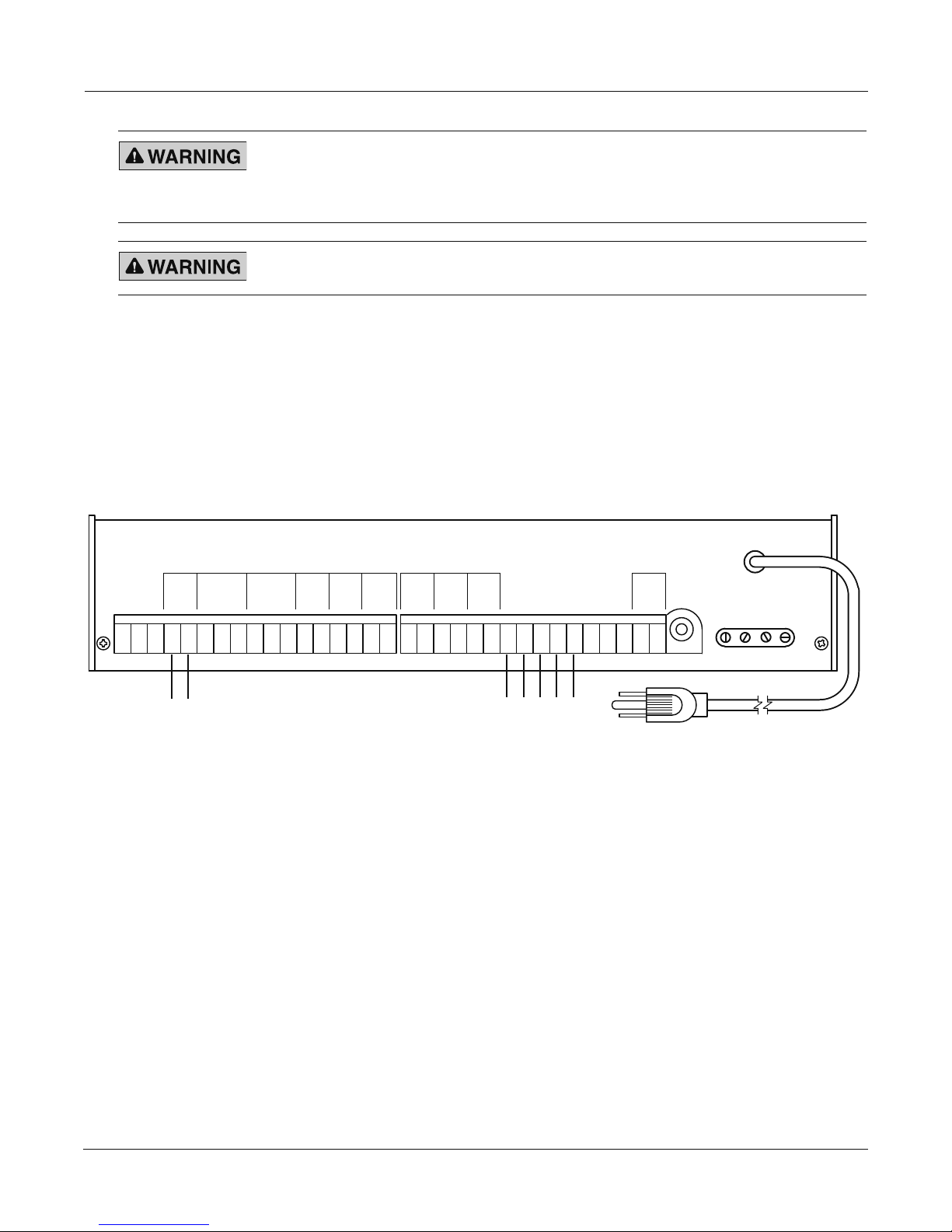
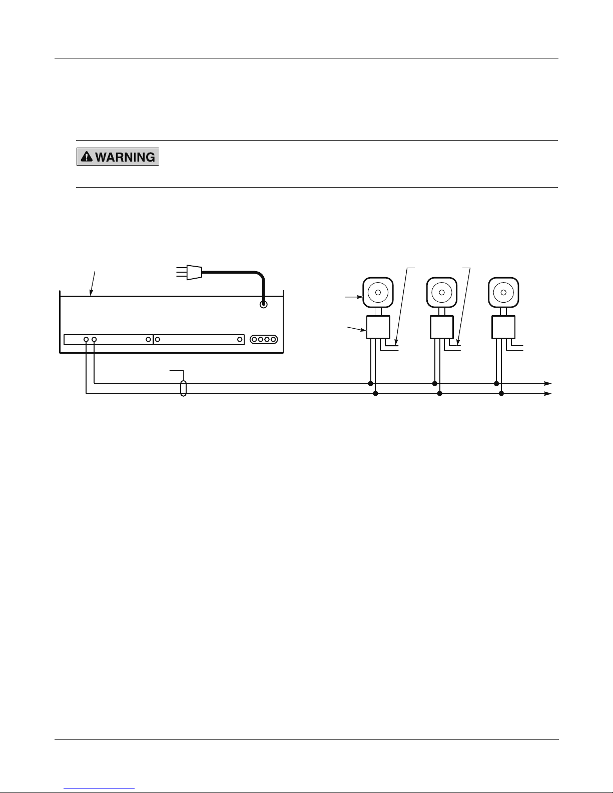
See Figure 1. To connect the signal lines of the SelecTone system to the 300VSC, connect a colorcoded twisted pair of audio cables having conductors no smaller than 18 AWG to the TB1-4 and TB1-5
terminals on TB1. Every remote SelecTone signaling device in the system can be connected in parallel
or series to these lines.
For non-SelecTone 25 Vrms speakers, such as ceiling speakers, connect the signal lines directly to
TB1-4 and TB1-5 of terminal block TB1. Signal line losses must be considered when calculating how
many speakers can be connected to the 300VSC.
Figure 1 Connections on the back of Model 300VSC
TONE 1
TONE 2
TONE 3
TONE 4
AUX
N.O.
COM.
RESET
N.O.
COM.
GND
TONE 1
TONE 2
FROM EXTERNAL
TONE 3
TONE 4
MIC AUDIO IN
25 VRMS
SIG OUT
SIG COM.
SIG HI
SIG 1V
SIG
SIG
N.O.
COM.
1 2 3 4 5 6 7 8 9 10 11 12 13 14 15 16 17 1 2 3 4 5 6 7 8 9 10 11 12 13 14 15 16
SHIELDED TWISTED
TEST
N.C.
N.O.
COM.
N.C.
N.O.
COM.
N.O.
COM.
N.O.
COM.
N.O.
COM.
TB1 TB2
PTT
MIC COM
24 VDC
-
+
AUX AUDIO IN
AUXPATONE
LEVEL CONTROLS
MIC
Connecting to Remote Devices
Install the remote SelecTone device(s) following the instructions included with the device.
Balanced Line Application
For 300GC, 300GCX, 300X, 302GC, 302GCX, 302X, or 50GC speakers, an AM25CK Connector Kit is
required for connection to the balanced signal output of the 300VSC. The AM25CK properly terminates
the balanced signal lines to the amplier in the 300GC, 300GCX, 300X, 302GC, 302GCX, 302X and
50GC. As shown in Figure 2 on page 12, connect the white input wires on the AM25CK to the terminals
TB1-4 and TB1-5 of terminal block TB1 on the 300VSC. The AM25CK and AM70CK Connector Kits
are NOT polarity sensitive, but you must observe polarity when placing speakers in close proximity to
each other.
Model 300VSC-1 and Model 300VSC-1044SB SelecTone Command Units
11

Installation and Maintenance Manual
ON REAR OF 300VSC
290A7318
Figure 2 Model AM25CK connections (balanced line)
300GC
AM25CK
4 5
TERMINAL BLOCK (TB1)
300GC
AM25CK
SHIELDED TWISTED-PAIR
SIGNAL LINE TO ADDITIONAL
SELECTONES
For 25 Vrms line-operated speakers, connect them directly to the balanced signal output of the 300VSC.
Connect the speakers in parallel to terminals TB1-4 and TB1-5 of terminal block TB1 on the 300VSC.
Unlike the unbalanced line output, this output is not switched.
IMPORTANT: Use the balanced signal output only if there are no SelecTone system devices connected
to the unbalanced signal output (across TB1-1 and TB1-2).
Unbalanced Line Application
See Figure 3. For existing SelecTone systems using the 300CK Connector Kit, use the unbalanced signal
outputs on the 300VSC. A 300CK Connector Kit is required to connect a 300GC, 300GCX, 300X,
302GC, 302GCX, 302X or 50GC to the unbalanced signal lines. The 300CK properly terminates the
signal lines to the amplier in the 300GC, 300GCX, 300X, 302GC, 302GCX, 302X and 50GC. Connect
the blue wire on the 300CK to the SIG COM wire from the 300VSC. Connect the yellow wire on the
300CK to the SIG HI wire from the 300VSC.
Figure 3 Model 300CK connections (unbalanced line)
300GC
300CK
YEL BLU YEL BLU
1 2
COM SIG
TERMINAL BLOCK (TB1)
ON REAR OF 300VSC
HI
300GC
300CK
SHIELDED TWISTED-PAIR
SIGNAL LINE TO
ADDITIONAL SELECTONES
Connecting a Low-Level Audio Output
The 300VSC also has a 1-volt peak-to-peak audio output that can be coupled to the audio input of
another amplier. This low-level output is available across terminals TB1-1 and TB1-2. It can also be
connected to an analog ber optic transmitter so that audio can be transmitted over a ber-optic link in
an electrically noisy environment.
12
Model 300VSC-1 and Model 300VSC-1044SB SelecTone Command Units
Installation and Maintenance Manual
1 2 3 4 5 6 7 8 9 10 11 12 13 14 15 16 17 1 2
GND
TONE 1
TONE 2
TONE 3
TONE 4
3 4 5 6 7 8 9 10 11 12 13 14 15 16
TB1 TB2
300VSC-1
TONE 2
REAR VIEW
(WITHOUT COVER)
TONE 4
TONE 1
TONE 3
TONE MODULES
OPTIONAL REMOTE SWITCH
CONTACTS
(CUSTOMER SUPPLIED)
S1
S2
S3
S4
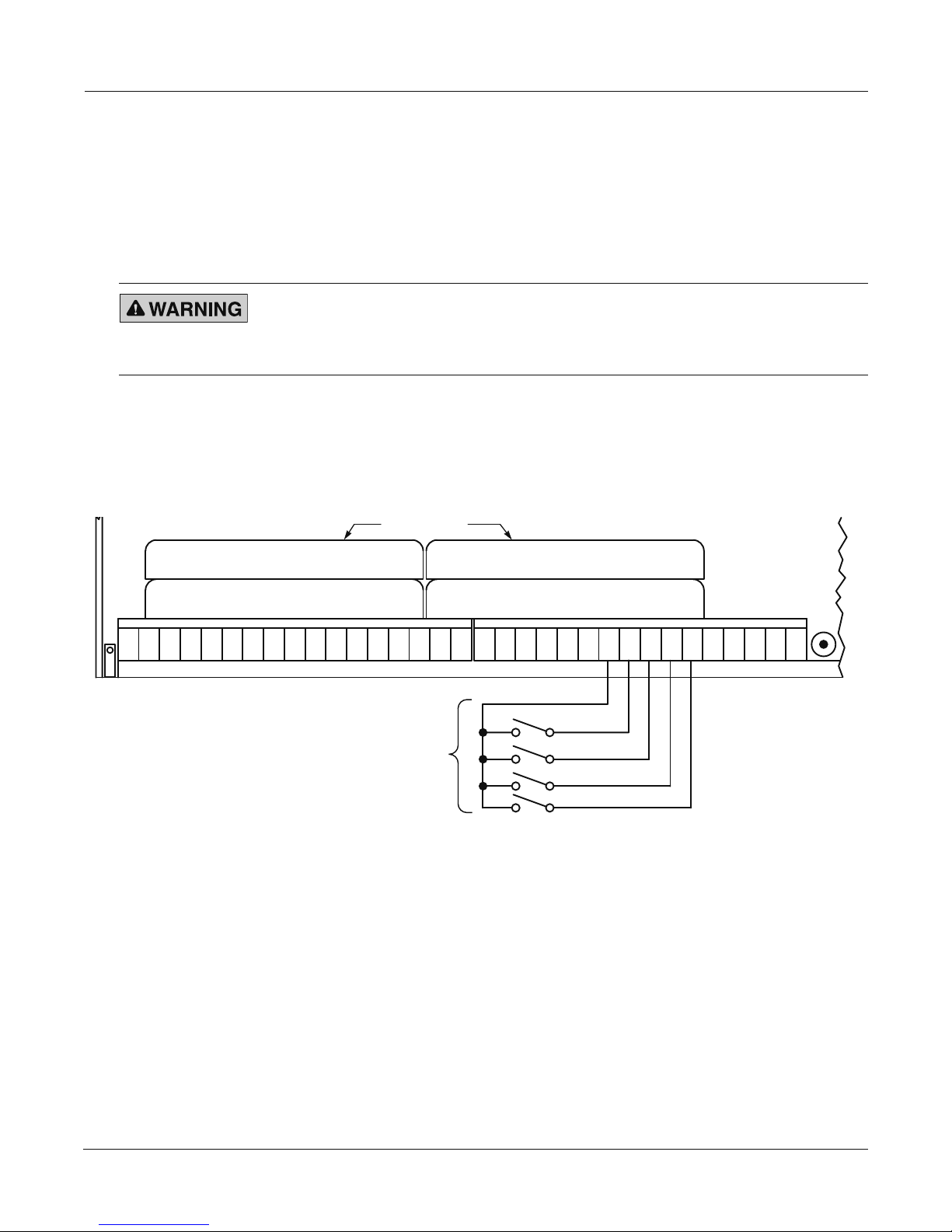
Connecting to Remote Switches for Tone Activation
The 300VSC tones can be activated remotely by any normally open, low-current switch contacts with a
current capacity of at least 50 mA inductive. Figure 4 illustrates the connection of switch contacts to the
300VSC. The designations S1, S2, S3 and S4 represent remote switch contacts such as those found in ow
switches, program clocks, heat detectors, and smoke detectors. The remotely activated tone sounds as long as
the activating contacts remain closed.
Installing SelecTone Tone Modules
SHOCK HAZARD — Do not perform any installation or maintenance on this
system when power is on. Because the 300VSC does not have a power
switch, ensure that the power is disconnected before proceeding. Failure to
heed this warning may cause serious injury or death.
See Figure 4. The 300VSC can accommodate up to four SelecTone tone modules of your choice. To
install the tone modules, insert them into the desired receptacles on the printed circuit board. The
receptacles for TONE 1 module and TONE 2 module are located on the motherboard. Receptacles for
TONE 3 module and TONE 4 modules are located on the card that plugs into the motherboard.
Figure 4 Remote switch contacts for tone modules 1 through 4
Model 300VSC-1 and Model 300VSC-1044SB SelecTone Command Units
13
Installation and Maintenance Manual
174 5 1 16
TB1
TB2
MODEL 300GC
MODEL 300VSC-1
MODEL AM25CK
SIGNAL LINES SHIELDED
TWISTED PAIR
120 Vac 120 Vac 120 Vac
LOCAL PWR. LOCAL PWR.
POWER LINES
120 Vac
Two Methods of Supplying Power to the SelecTone System
The two basic methods of supplying power to a SelecTone system are 120 Vac 50/60 Hz local power and
24 Vdc central power. The next paragraphs describe each method along with the advantages and disadvantages.
120 Vac 50/60 Hz Local Power
INSTALLATION PRECAUTION — Improper installation could render this
system inoperable, interfering with the warning nature of this product. The
installation must conform to applicable local and/or National Electrical codes.
See Figure 5. In this system, power is supplied to each remote SelecTone device by connecting it to a
120 Vac supply in the immediate vicinity of the device. If an emergency power source is required, a
central power system as described below should be employed.
Figure 5 Typical local power system
24 Vdc Central Power
See Figure 6 on page 15. In the central power system, all of the remote amplier power lines are
connected in parallel to one or more centrally located power sources that are 24 Vdc.
The advantages of a central power system are:
✓
The entire system may be independent of local line voltage.
✓ The entire system can be switched to an emergency standby power source in the event of a power failure.
✓ The central power system has the added advantage that an auxiliary power supply, such as the
Federal Signal Model PS600 can be used to power the remote devices in the SelecTone system.
If the PS600 is used, it is not necessary to switch the power source if a power failure occurs.
The disadvantages of a central power system are:
✓
Heavy power lines are required from the power source to the remote devices in the system. The size
of the power lines is dependent upon the number of ampliers and the total distance of the power
loop in order to minimize the voltage drop while a tone signal is being generated.
Future expansion is limited by the current capacity of the power source and the power lines that
14
✓
✓
were initially installed.
Central power installations must comply with local electrical codes. Most power circuits are Class I
circuits. Therefore, conduit will probably be required. Installation costs are higher than a local
power system.
Model 300VSC-1 and Model 300VSC-1044SB SelecTone Command Units
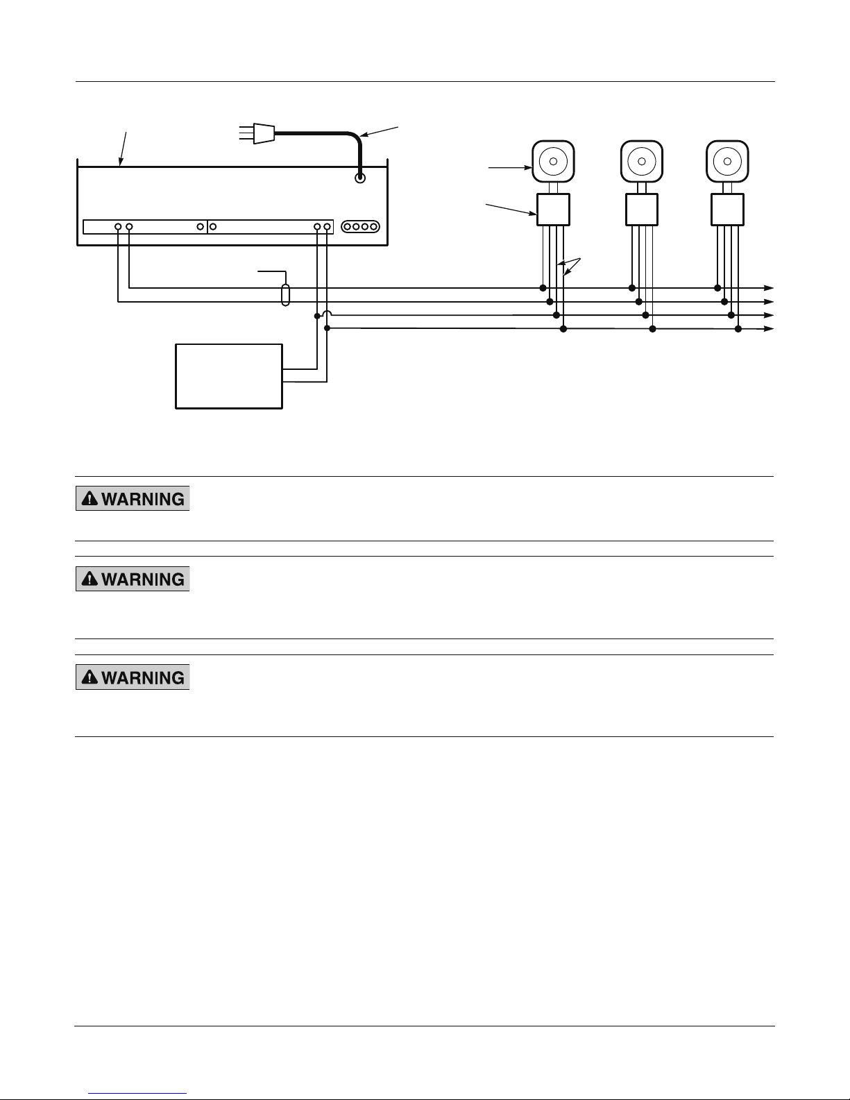
Figure 6 Typical central power system
290A7326
POWER
LINES
MODEL 300GC
24 Vdc
MODEL AM25CK
SIGNAL LINES SHIELDED
TWISTED PAIR
NOT USED WITH MODEL PS600
24 Vdc
POWER SUPPLY
+
+––
54 17 1 1615
TB1
TB2
MODEL 300VSC-1
120 Vac
OUTPUT
Connecting Power to the SelecTone System
Installation and Maintenance Manual
Connect operating power to the 300VSC by inserting the plug end of the line cord into any standard 120 volt,
60 Hz outlet. The 300VSC is factory-set for 120 Vac 50/60 Hz operation.
If using 24 Vdc either as a primary or auxiliary source of power, connect the “+” terminal of 24 Vdc power
supply to the terminal TB2-15 (+24 Vdc) and “–” terminal of the 24 Vdc power supply to the terminal
TB2-16 (-24 Vdc) of the TB2 terminal block located in the back of 300VSC.
INSTALLATION PRECAUTION — This device is to be installed by a trained
electrician who is thoroughly familiar with the national electrical code and local
codes and will follow the guidelines.
SHOCK HAZARD — Do not perform any installation or maintenance on this
system when power is on. Because the 300VSC does not have a power switch,
ensure that the power is disconnected before proceeding. Failure to heed this
warning may cause serious injury or death.
CROSSTALK/INTERFERENCE HAZARD — Cross talk, interference, or hum can be
induced in signal lines, causing poor audio output or confusing messages, which
interferes with the emergency warning capability of this equipment.
Do not install power lines in the same conduit as signal lines.
Model 300VSC-1 and Model 300VSC-1044SB SelecTone Command Units
15
Installation and Maintenance Manual
Model 300VSC-1 and Model 300VSC-1044SB SelecTone Command Units
Safety Messages to Maintenance Personnel
This device is to be serviced by a trained electrician who is thoroughly familiar with the National Electric
Code and will follow the NEC guidelines as well as local codes.
This service information is for qualied personnel only. To avoid electric shock, do not perform any servicing
other than changing fuses, unless qualied to do so. Refer all servicing to qualied service personnel.
Listed below are some important safety instructions and precautions you should follow:
• Read and understand all instructions before operating this system.
• Do not perform any maintenance on this system when power is on. Because the 300VSC does not have a
power switch, ensure that the power is disconnected before proceeding.
• Always insure that the power to the 300VSC is disconnected before removing the metal cover.
• Do not disconnect or connect this unit to the system when power is on.
• All effective warning speakers produce loud sounds which may cause, in certain situations, permanent
hearing loss. You should take appropriate precautions such as wearing hearing protection.
• After installation, test the sound system to ensure proper operation.
• Establish a procedure to routinely check the sound system for proper activation and operation.
Failure to follow all safety precautions and instructions may result in property damage, serious injury, or death.
Getting Replacement Parts
Typical replacement parts are listed below. To order the accessories and replacement parts in Table 2, please
call Federal Signal Customer Support at 708-534-4756 or 877-289-3246.
Table 2 Replacement parts
Description Part Number
Motherboard K2001154
Switch board (300VSC-1) K2001147
Tone card connector board K2001164
Connector plug, TB1, 17-position K140A332-17
Connector plug, TB2, 16-position K140A332-16
Getting Repair Service or Technical Assistance
Products returned for repair require a Return Authorization form from your local distributor or from
Federal Signal. To obtain repair service or technical assistance from Federal Signal, call 708-534-4756
or 877-289-3246. For instruction manuals and information on related products, visit:
http://www.federalsignal-indust.com.
16

Installation and Maintenance Manual
Model 300VSC-1 and Model 300VSC-1044SB SelecTone Command Units
Returning a Product for Credit
Product returns for credit require a return authorization from your local distributor prior to returning the
product to Federal Signal. Please contact your distributor for assistance.
A product is qualied to be returned for credit when the following conditions are met:
• Product is resalable and in the original cartons
• Product has not been previously installed
• Product is the current revision
• Product has not been previously repaired
• Product is a standard product
• Product is not a service part
All returns are subject to a re-stock fee.
Defective products that are returned within the warranty period will be repaired or replaced at Federal
Signal’s sole discretion. Defective products do not include those products with lamp failure.
Circumstances other than those listed above will be addressed on a case-by-case basis.
17

Industrial Systems
2645 Federal Signal Drive • University Park, IL 60484-3167
Tel: 708-534-4756 • 877-289-3246 • Fax: 708-534-4852
Email: elp@federalsignal.com • www.federalsignal-indust.com • www.fs-isys.com
18

Systèmes de commande SelecToneMD
300VSC-1 et 300VSC-1044SB
modèle 300VSC-1044SB
Manuel d'installation et d'entretien
2561044F
Rev. F0 913
Imprimé aux États-Unis
modèle 300VSC-1
èle MSB-1
mod
19

ans
G
A
R
A
Garantie – Le vendeur offre pour tous les produits une garantie de cinq ans sur les pièces et de 2,5 ans sur la maind’oeuvre, selon les conditions et exceptions suivantes : le vendeur garantit que tous les produits qu’il fabrique seront
conformes aux descriptions correspondant aux spécications qui font expressément partie de ce contrat de vente et
qu’au moment de la vente par le vendeur, de tels produits devront être exempts de défauts de matériel et de fabrication. Le vendeur se réserve le droit, à sa discrétion, de « réparer et renvoyer » ou de « remplacer » tout article jugé
défectueux durant la période de garantie. Cette garantie ne couvre pas les frais de voyage, le coût de l’équipement
spécialisé pour avoir accès au produit ou les frais de main-d’oeuvre liés au retrait et à la réinstallation du produit.
Cette garantie sera inopérante et ne s’appliquera pas aux produits qui ont subi un mauvais usage, une négligence,
un accident, des dommages ou un entretien inapproprié, ou aux produits modiés ou réparés par toute personne
autre que le vendeur ou son représentant autorisé, ou si cinq ans se sont écoulés depuis la date de l’envoi des
produits par le vendeur avec les exceptions suivantes : les lampes et les tubes stroboscopiques ne sont pas couverts par cette garantie. Les sirènes d’alarme extérieures et les appareils de contrôle fabriqués par Federal Warning
Systems sont couverts par une garantie de deux ans sur les pièces et de un an sur la main-d’oeuvre. Aucun agent,
employé, représentant ou distributeur du vendeur n’a autorité pour lier celui-ci à une représentation, afrmation
ou garantie relative aux produits et une telle représentation, afrmation ou garantie ne pourra pas être considérée
comme faisant partie des généralités du contrat de vente et sera inexécutable. LES GARANTIES CI-DESSUS
SONT EXCLUSIVES ET TIENNENT LIEU DE TOUTES LES AUTRES GARANTIES DE QUALITÉ MARCHANDE,
DE COMPATIBILITÉ À UN USAGE PARTICULIER OU D’UN AUTRE TYPE, QU’ELLES SOIENT EXPRESSES
OU IMPLICITES. Ces garanties ne s’appliqueront pas si le vendeur n’a pas la possibilité raisonnable d’enquêter
sur toutes les réclamations de produits présumés défectueux. À la demande du vendeur, un seul échantillon des
produits présumés défectueux lui sera renvoyé pour inspection et approbation. La raison de toute réclamation pour
des défauts présumés dans les produits ne pouvant être découverts après une inspection raisonnable en vertu du
paragraphe 8 ci-contre doit être entièrement expliquée par écrit et reçue par le vendeur dans les trente jours après
que l’acheteur a pris connaissance du défaut. Sinon, une telle réclamation sera considérée comme nulle.
E
I
T
N
2645 Federal Signal Drive • University Park, IL 60484
Tel: 708-534-4756 • 877-289-3246. Fax: 708-534-4852
elp@fedsig.com • www.federalsignal-indust.com
20
• www.fs-isys.com

Systèmes de commande SelecToneMD 300VSC-1 et 300VSC-1044SB
Tableau des matières
Avertissement de sécurité destiné aux installateurs des produits Federal Signal ........................ 23
Déballage du produit
Aperçu du produit
............................................................................................................................ 23
................................................................................................................................ 23
Dimensions et caractéristiques du châssis ...................................................................................................24
Caractéristiques du panneau avant
Caractéristiques du circuit de commande
Bouton CANCEL
Bouton TEST
Puissance nécessaire
Entrées audio
Recommandation concernant les lignes d'acheminement des signaux ........................................ 28
.........................................................................................................................................25
...............................................................................................................................................25
....................................................................................................................................25
...............................................................................................................................................25
...............................................................................................................24
....................................................................................................24
Branchement des lignes d'acheminement des signaux ................................................................................29
Branchement aux appareils à distance .............................................................................................. 29
Utilisation de lignes symétriques .................................................................................................................29
Utilisation de lignes dissymétriques
Branchement d'une sortie audio de faible intensité
Branchement à des interrupteurs à distance permettant d'activer les tonalités ........................... 31
............................................................................................................30
.....................................................................................31
Installation des modules de tonalité SelecTone ...........................................................................................31
Deux méthodes d'alimentation du système SelecTone .................................................................... 32
Alimentation locale de 120 Vcc et 50/60 Hz ...............................................................................................32
Alimentation centrale de 24 Vcc
Branchement de l'alimentation au système SelecTone .................................................................... 33
Messages de sécurité destinés au personnel d'entretien
Obtention de pièces de rechange
Service de réparation et assistance technique
Renvoi du produit pour obtention d’un crédit
Tableau 1 Caractéristiques techniques .............................................................................................................26
Tableau 2 Pièces de rechange
.................................................................................................................32
................................................................ 34
....................................................................................................... 34
................................................................................. 35
................................................................................... 35
Tableaux
.........................................................................................................................34
21

Systèmes de commande SelecToneMD 300VSC-1 et 300VSC-1044SB
Figures
Figure 1 Raccordements à l'arrière de 300VSC Modèle ................................................................................. 29
Figure 2 AM25CK connections (balanced line)................................................................................................ 30
Figure 3 Branchements de l'ensemble 300CK (ligne dissymétrique)
Figure 4 Contacts d'interrupteur à distance pour modules de tonalité 1 à 4
Figure 5 Système type d'alimentation locale
Figure 6 Système type d'alimentation centrale
................................................................................................... 32
................................................................................................ 33
.............................................................. 30
................................................... 31
Selectone est une marque déposée de Federal Signal Corporation.
© 2013 Federal Signal Corporation. Tous droits réservés.
22

Manuel d'installation et d'entretien
Avertissement de sécurité destiné aux installateurs des produits Federal Signal
AVERTISSEMENT
Des vies dépendent de la manière dont vous installez et entretenez les produits de Federal Signal. Il est
important de lire et de respecter les instructions qui accompagnent ce produit. De plus, voici d'autres
précautions et instructions importantes à observer en matière de sécurité :
• Cet appareil doit être installé par un électricien qualié qui connaît parfaitement le Code national de
l'électricité ou les codes locaux et en suivra les directives.
• Consultez les autorités compétentes de votre région concernant la bonne utilisation et l'installation de ce
produit.
• Le choix du lieu d'installation de l'appareil, les commandes et le passage des câbles doivent s'effectuer
sous la direction de l'ingénieur des installations et de l'ingénieur de la sécurité.
• Il faut bien lire et comprendre toutes les instructions avant d'installer ou d'utiliser cet appareil.
• Ne branchez pas cet appareil au réseau lorsqu'il est allumé.
• La diffusion sonore sera considérablement réduite si des objets se trouvent devant le haut-parleur. Faites
en sorte que cet emplacement soit dégagé.
• Tous les haut-parleurs d'avertissement efcaces produisent des sons forts susceptibles, dans certaines
situations, d'entraîner une perte auditive permanente. Prenez les précautions qui s'imposent, par exemple,
en portant un dispositif de protection antibruit.
• Après l'installation, testez le système sonore pour vérier son bon fonctionnement.
• Montrez ces instructions à votre ingénieur de la sécurité, puis classez-les en lieu sûr et consultez-les
lorsque vient le moment d'entretenir ou de réinstaller l'appareil.
• Établissez une procédure de vérication régulière de l'activation et du bon fonctionnement du système sonore.
Le non-respect de toutes les précautions et instructions de sécurité peut provoquer des dommages à la propriété,
des blessures graves voire la mort.
Déballage du produit
Après avoir déballé le produit, inspectez-le pour vérier qu'aucun dommage n'est survenu lors du transport.
Si le modèle 300VSC-1 ou 300VSC-1044B a été endommagé, n'essayez pas de l'installer ou de l'utiliser.
Déposer immédiatement une réclamation auprès du transporteur en précisant l'étendue des dégâts. Vérier
avec soin toutes les enveloppes, étiquettes d'expédition et autres étiquettes avant de les retirer ou de les
détruire. La mise au rébus de tout matériel de transport doit être effectuée conformément aux normes et codes
locaux et nationaux. En cas de pièces manquantes, communiquez avec le Service à la clientèle de Federal
Signal au 708-534-4756 ou au 877-289-3246.
Aperçu du produit
Le système de commande SelecToneMD 300VSC est un dispositif de commande centralisée pouvant
produire jusqu'à quatre tonalités sur une ligne branchée à un haut-parleur ou à des amplicateurs à distance
d'un système SelecTone. Le modèle 300VSC peut commander des lignes d'acheminement des signaux
vers des haut-parleurs ou des amplicateurs des modèles Federal Signal 300GC, 300GCX, 300X, 302GC,
Systèmes de commande SelecToneMD 300VSC-1 et 300VSC-1044SB
23

Manuel d'installation et d'entretien
302GCX, 302X et 50GC ainsi que vers d'autres dispositifs conçus pour fonctionner avec un système
SelecTone. Il peut également commander des signaux vers des haut-parleurs conçus pour des lignes de
25 Vrms. Le modèle 300VSC possède une fonction de sonorisation permettant d'annoncer des instructions
ou des messages vocaux sur le système SelecTone grâce à un microphone MSB-1 ou MNC-1 en option.
L'appareil peut également servir à diffuser sur le système SelecTone de la musique de fond provenant d'une
source externe.
Le modèle MNC-1 est un microphone antibruit à main idéal pour une utilisation locale. Le modèle MSB-1
est un microphone de station de base prévu pour être utilisé sur un bureau.
Le modèle 300VSC-1 est destiné à être installé à l'extérieur, sur un bureau ou une surface plate.
Le modèle 300VSC-1044B s'installe sur un bâti. Il est livré avec la quincaillerie de montage. Il convient à
toutes les armoires à bâti standard de 48 cm (19 po).
Le modèle 300VSC produit et amplie des tonalités et des signaux audio et les transmet par des lignes
d'acheminement des signaux vers les appareils SelecTone à distance du système. Chaque dispositif SelecTone
doit être branché à la ligne d'acheminement des signaux à l'aide d'un ensemble connecteur AM25CK. Les
haut-parleurs de 25 volts se branchent directement à la sortie de 25 volts. Le modèle 300VSC est conçu pour
accueillir jusqu'à quatre modules de tonalité de votre choix. Les tonalités sont désignées par les noms Tone 1,
Tone 2, Tone 3 et Tone 4. Chacune d'entre elles peut être activée manuellement de manière locale grâce au
bouton correspondant du panneau avant, ou à distance en fermant le contact de l'entrée associée. Lorsqu'une
tonalité est activée, que ce soit localement ou à distance, le voyant DEL correspondant du panneau avant
clignote pour l'indiquer. Il reste allumé jusqu'à ce que la tonalité soit désactivée et que le contact soit rouvert.
Toutes les commandes du modèle 300VSC se trouvent sur son panneau avant.
Les détails et les fonctions du produit sont décrits dans les sections suivantes. Pour obtenir l'intégralité des
caractéristiques techniques du produit, consultez le tableau 1, aux pages 26 à 28.
Dimensions et caractéristiques du châssis
Le modèle 300VSC-1 consiste en un boîtier noir d'aluminium brossé composé de deux parties, d'une
largeur de 26,67 cm (10,50 po), d'une profondeur de 23,50 cm (9,25 po) et d'une hauteur de 6,18 cm
(2,44 po) environ. Il se pose sur une surface plate horizontale ou s'installe au mur grâce aux supports
muraux fournis dans l'ensemble d'accessoires. Le boîtier est assemblé à l'aide de quatre vis, dont deux
sont situées sur le dessous, près de l'avant et les deux autres à l'arrière, près des borniers.
Le modèle 300VSC-1044SB est constitué d'un boîtier d'aluminium en trois parties. Peint en noir, il
mesure 48,26 cm (19 po) de largeur, 25,40 cm (10 po) de profondeur et 8,89 cm (3,5 po) de hauteur.
L'appareil est installé dans une armoire à bâti standard de 48,26 cm (19 po).
Caractéristiques du panneau avant
Les interrupteurs du panneau avant portent les mentions TONE 1 à TONE 4, AUX, TEST et CANCEL.
Il est possible d'indiquer la nature de tonalité correspondant à chaque interrupteur en écrivant son nom
dans la zone blanche toute proche à l'aide d'un marqueur permanent à pointe de feutre. Si vous changez
de tonalité ou de message, effacez la mention en frottant légèrement à l'aide d'un chiffon imbibé d'alcool
dénaturé. Pour éviter d'abîmer les interrupteurs, veillez à ce que l'alcool n'entre pas en contact avec eux.
Caractéristiques du circuit de commande
Le circuit de commande du modèle 300VSC a une fonction de priorité intégrée. Si une tonalité dont
la priorité est plus élevée est activée localement ou à distance alors qu'une tonalité donnée sonne déjà,
Systèmes de commande SelecToneMD 300VSC-1 et 300VSC-1044SB
24

Manuel d'installation et d'entretien
la première a automatiquement préséance sur la deuxième. Toutefois, le voyant DEL du bouton de la
deuxième tonalité reste allumé pour indiquer qu'elle reste activée. Lorsque la tonalité prioritaire est
désactivée, le voyant DEL du bouton s'éteint et la tonalité moins prioritaire retentit de nouveau.
Le bouton
CANCEL permet de désactiver les tonalités actives. La priorité la plus élevée est accordée
au microphone local. Le numéro associé aux tonalités correspond à leur ordre séquentiel de priorité. En
outre, toutes les tonalités ont priorité sur la sonorisation à distance et sur la musique de fond.
Étant donné que la tonalité 1 (Tone 1) a priorité sur toutes les autres, le module TM9 « Hululement lent »
est souvent installé à la position Tone 1 comme signal d'alarme. Lorsque le modèle 300VSC est activé hors
du mode Test (voir « Bouton TEST » ci-dessous), un relais intégré ouvre un ensemble de contacts repos
et ferme une série de contacts travail, ce qui permet d'envoyer un signal d'alarme à d'autres services ou
circuits d'urgence. Pour connaître les types de tonalités à utiliser, consultez les codes locaux.
Bouton CANCEL
Le bouton CANCEL (Annuler) réinitialise toutes les fonctions de signalisation du modèle 300VSC
activées manuellement. En outre, il établit une fermeture temporaire de contact sec, ce qui facilite la
réinitialisation à distance des autres circuits d'alarme. Le contact reste fermé tant que vous appuyez
sur le bouton CANCEL (Annuler). L'activation à distance ne pourra pas être réinitialisée tant que la
fermeture sera maintenue à l'entrée à distance.
Bouton TEST
Le bouton TEST permet de tester les tonalités sans activer les haut-parleurs sur des circuits
dissymétriques d'acheminement des signaux. Pendant le test, la tonalité n'est produite que dans le
moniteur de contrôle se trouvant dans le boîtier. Le bouton TEST permet également d'annuler les fausses
alarmes. Une fois que vous avez appuyé sur le bouton, le voyant DEL reste allumé pour vous rappeler
d'appuyer sur le bouton CANCEL lorsque le test est terminé ou que la fausse alarme est annulée.
Puissance nécessaire
AVERTISSEMENT
Le panneau avant est équipé d'un voyant DEL vert qui indique la présence d'énergie primaire. Le
modèle 300VSC peut être alimenté en 120 Vca ou 24 Vcc. Un cordon électrique permet de l'alimenter
en 120 Vca, tandis que les borniers arrière servent à l'alimentation en 24 Vcc.
RISQUE DE DÉCHARGE ÉLECTRIQUE— Pour éviter qu'il soit éteint
par accident, le modèle 300VSC ne possède pas d'interrupteur
d'alimentation et reste sous tension jusqu'à ce que l'alimentation soit
coupée. Avant une installation ou l'entretien, débranchez l'alimentation
du modèle 300VSC.
Entrées audio
Il est possible de brancher directement un microphone au modèle 300VSC en utilisant les ches
modulaires se trouvant à l'avant. La priorité la plus élevée est accordée au microphone. Des bornes à vis
sont cependant prévues au dos du modèle 300VSC pour l'entrée d'un signal audio de faible intensité et
de basse impédance. Les borniers permettent de coupler l'audio provenant d'un système téléphonique
de PBX avec l'interface adaptée fournie par la compagnie de téléphone. Cette entrée permet également
le branchement direct d'un microphone distant à basse impédance avec bouton micro distinct, qui a la
priorité sur les tonalités. La che RCA située au dos du châssis permet de recevoir des signaux audio
standard de 1 volt provenant d'une source émettrice de musique de fond comme un récepteur radio, un
lecteur de CD ou un lecteur de cassettes.
Systèmes de commande SelecToneMD 300VSC-1 et 300VSC-1044SB
25

Manuel d'installation et d'entretien
Tableau 1 Caractéristiques techniques
Puissance à l'entrée
Tension d'entrée 120 Vca, 50 Hz à 60 Hz
Courant d'attente 50 mA, 120 Vca
Courant de fonctionnement 210 mA (max)
Consommation électrique 26 W (max.)
Entrée de l'alimentation de secours
Tension d'entrée
Courant d'attente 90 mA
Courant de fonctionnement 760 mA
Entrées audio
Sonorisation locale (avec microphone MSB-1 en option)
Impédance d'entrée 5 kΩ
Tension d'entrée 16 mVrms (max)
Microphone à distance
Impédance d'entrée 5 kΩ
Tension d'entrée 16 mVrms (max)
22 Vcc à 32 Vcc
Entrée auxiliaire
Impédance d'entrée 5 kΩ
Tension d'entrée 500 mVrms (max.)
Sorties audio
Impédance de sortie
Ligne dissymétrique d'acheminement des signaux 25 Ω (max.)
Ligne dissymétrique d'acheminement des signaux, en attente 120 Ω
Ligne symétrique d'acheminement des signaux 40 Ω (max.)
Ligne d'acheminement des signaux à faible intensité 600 Ω
Seuils de tensions de sortie, hors charge (taux d'harmoniques < 3 %)
Ligne dissymétrique d'acheminement des signaux 9 Vrms
Ligne symétrique d'acheminement des signaux 17 Vrms
Ligne d'acheminement des signaux à faible intensité 1 V crête à crête
Seuils de tension de sortie, charge max. (taux d'harmoniques < 3 %)
Ligne dissymétrique d'acheminement des signaux 8 Vrms (25 Ω load)
Ligne symétrique d'acheminement des signaux 15 Vrms (40 Ω load)
Ligne d'acheminement des signaux à faible intensité 1 V crête à crête (600 Ω charge)
Systèmes de commande SelecToneMD 300VSC-1 et 300VSC-1044SB
26

Manuel d'installation et d'entretien
Tableau 1 Caractéristiques techniques (suite)
Seuils de tension de sortie, hors charge (en ondes carrées)
Ligne dissymétrique d'acheminement des signaux 12 Vrms
Ligne symétrique d'acheminement des signaux 25 Vrms
Ligne d'acheminement des signaux à faible intensité 1 V crête à crête
Seuils de tension de sortie de la tonalité, charge max. (en ondes carrées)
Ligne dissymétrique d'acheminement des signaux 12 Vrms (25 Ω charge)
Ligne symétrique d'acheminement des signaux 20 Vrms (40 Ω charge)
Ligne d'acheminement des signaux à faible intensité 0.56 Vrms (600 Ω charge)
Réponse audiofréquence, ligne symétrique d'acheminement des signaux
Charge max. de 40 Ω, de 250 Hz à 80 kHz
(référence 1 kHz) -3 dB
Charge max. de 40 Ω, de 450 Hz à 60 kHz
(référence 1 kHz) -1 dB
Hors charge, de 100 Hz à 90 kHz
(référence 1 kHz) -3 dB
Hors charge, de 200 Hz à 60 kHz
(référence 1 kHz) -1 dB
Rapport signal sur bruit (taux d'harmoniques < 3 %)
Sonorisation locale 60 dB
Micro à distance 40 dB
Entrée aux. 80 dB
Distorsion audio de l'entrée aux. vers le signal symétrique
Sortie de ligne (charge de 40 Ω) 2 %
Haut-parleur interne
Niveau sonore à 1 mètre 65 dB
Circuit d'activation à distance de la tonalité
Type Fermeture de contact sec
Impédance de ligne 100 Ω (max.)
Courant du circuit 50 mA (max.) (12 Vdc)
Circuit d'activation à distance du microphone (avec bouton micro)
Type Fermeture de contact sec
Impédance de ligne 100 Ω (max.)
Courant du circuit 10 mA (max.) (12 Vcc)
Sorties de fermeture de contact à distance
Relais Tone 1, Tone 2, Tone 3, Tone 4, Sig. Out, Aux., Test et Cancel
Type Fermeture de contact sec
Catégorie 24 Vcc, 1 A, résistif
Systèmes de commande SelecToneMD 300VSC-1 et 300VSC-1044SB
27

Manuel d'installation et d'entretien
Tableau 1 Caractéristiques techniques (suite)
Rapport signal sur bruit (taux d'harmoniques < 3
Sonorisation locale 60 dBA
Micro à distance 40 dBA
Entrée aux. 80 dBA
Distorsion audio de l'entrée aux. au signal symétrique
Sortie de ligne (charge de 40 Ω)
Fusibles
F1 Type GMC-1, 1 A, 250 V
F2 Type GMC-1/2, 1/2 A, 250 V
Dimensions et poids
Modèle VSC-1
Poids 4,3 lb (1,95 kg)
Dimensions (L, P, H)
Modèle VSC-1044SB
Poids 7,9 lb (3,58 kg)
Dimensions (L, P, H)
2 %
10,5 po x 9,25 po x 2,44 po
26,67 cm x 23,50 cm x 6,20
48,26 cm x 24,40 cm x 8,89 cm
(19,0 po x 10,0 po x 3,5 po)
%)
Recommandation concernant les lignes d'acheminement des signaux
AVERTISSEMENT
Les lignes d'acheminement des signaux transfèrent les tonalités et les messages verbaux de l'appareil
300VSC vers les dispositifs SelecTone à distance. Pour réduire les risques de diaphonie, de bourdonnement
et de bruits parasites, les lignes d'acheminement des signaux doivent être faites de câbles audio à paires
torsadées blindées. La plupart des systèmes utilisent des câbles audio à paires torsadées blindées de diamètre
18 AWG. Pour les raisons suivantes, Federal Signal déconseille l'utilisation de lignes téléphoniques neuves
ou déjà posées pour acheminer les signaux dans un système SelecTone :
✓ Interférences provenant d'autres services ou systèmes, ou du système ou autres services
✓ Diaphonie, interférences ou bourdonnements générés par d'autres lignes téléphoniques
✓ Coût supplémentaire découlant de l'installation, des interfaces et des frais mensuels par rapport au coût
unique de l'installation
Coût supplémentaire découlant de l'installation, des interfaces et des frais mensuels par rapport au coût
✓
unique de l'installation
RÉDUCTION DE LA SORTIE SONORE — Si un câble d'un diamètre trop petit
est utilisé, il se produira une chute inacceptable de la tension du signal
dans la ligne d'acheminement des signaux, ce qui réduira la sortie du son
de l'appareil de signal à distance. N'utilisez que des câbles d'un diamètre
supérieur à 22 AWG.
Systèmes de commande SelecToneMD 300VSC-1 et 300VSC-1044SB
28

Manuel d'installation et d'entretien
AVERTISSEMENT
Branchement des lignes d'acheminement des signaux
AVERTISSEMENT
RISQUES DE DIAPHONIE ET D'INTERFÉRENCE — L'utilisation combinée
de lignes électriques avec des lignes d'acheminement des signaux peut
provoquer la diaphonie, des interférences ou du bourdonnement sur ces
dernières, et compromettre les fonctions d'avertissement d'urgence de
cet équipement. N'installez aucune ligne électrique dans le conduit où
passent les lignes d'acheminement des signaux.
RISQUE DE DÉCHARGE ÉLECTRIQUE — N'installez pas de lignes
d'acheminement des signaux dans le conduit où passent des lignes
électriques. Évitez de passer des lignes d'acheminement des signaux dans
des chemins où passent des lignes à haute tension.
Consultez la gure 1. Pour brancher les lignes d'acheminement des signaux du système SelecTone au
modèle 300VSC, branchez des câbles audio à paires torsadées et à code-couleur dont les conducteurs
sont d'un calibre supérieur ou égal à 18 aux bornes TB1-4 et TB1-5 du bornier TB1. Chaque appareil de
signalisation à distance SelecTone du système peut être branché à ces lignes en parallèle ou en série.
En ce qui concerne les haut-parleurs de 25 Vrms qui ne sont pas de la marque SelecTone, comme les
haut-parleurs de plafond, branchez directement les lignes d'acheminement des signaux aux bornes
TB1-4 et TB1-5 du bornier TB1. Il faut tenir compte des affaiblissements de ligne d'acheminement des
signaux lorsque vous calculez le nombre de haut-parleurs pouvant être branchés au modèle 300VSC.
Figure 1 Raccordements à l'arrière de 300VSC Modèle
TONE 1
TONE 2
TONE 3
TONE 4
AUX
25 VRMS
SIG OUT
SIG COM.
SIG HI
SIG 1V
SIG
SIG
N.O.
1 2 3 4 5 6 7 8 9 10 11 12 13 14 15 16 17 1 2 3 4 5 6 7 8 9 10 11 12 13 14 15 16
LIGNES D'ACHEMINEMENT DES SIGNAUX
EN PAIRES TORSADÉES BLINDÉES
TEST
COM.
N.C.
N.O.
COM.
N.C.
N.O.
COM.
N.O.
COM.
N.O.
COM.
N.O.
COM.
TB1 TB2
RESET
N.O.
COM.
N.O.
COM.
GND
TONE 1
TONE 2
ARRIVÉE DEPUIS LES
DISPOSITIFS
DE COMMANDE EXTERNES
TONE 3
TONE 4
MIC AUDIO IN
PTT
MIC COM
24 VDC
AUX AUDIO IN
-
+
(CONTRÔLE DU NIVEAU SONORE)
AUXPATONE
LEVEL CONTROLS
MIC
Branchement aux appareils à distance
Installez le ou les appareils SelecTone à distance en respectant les instructions qui les accompagnent.
Utilisation de lignes symétriques
Les haut-parleurs 300GC, 300GCX, 300X, 302GC, 302GCX, 302X et 50GC exigent l'utilisation d'un
ensemble connecteur AM25CK destiné à la sortie de signal symétrique du modèle 300VSC. Cet ensemble
permet de faire aboutir les lignes symétriques d'acheminement des signaux vers l'amplicateur dans les
haut-parleurs 300GC, 300GCX, 300X, 302GC, 302GCX, 302X et 50GC. Comme illustré à la gure 2 de
la page 30, branchez les ls d'entrée blancs de l'ensemble AM25CK aux bornes TB1-4 et TB1-5 du bornier
TB1 de l'appareil 300VSC. Les ensembles connecteurs AM25CK et AM70CK ne sont PAS sensibles à la
polarité, mais il faut toutefois respecter cette dernière si vous placez les haut-parleurs près l'un de l'autre.
290A7488
Systèmes de commande SelecToneMD 300VSC-1 et 300VSC-1044SB
29

Manuel d'installation et d'entretien
290A7490
L'ARRIÈRE DU MODÈLE300VSC
Figure 2 AM25CK connections (balanced line)
300GC
AM25CK
4 5
BORNIER (TB1) SITUÉ À
L'ARRIÈRE DU MODÈLE300VSC
300GC
AM25CK
LIGNES D'ACHEMINEMENT DES SIGNAUX
EN PAIRES TORSADÉES BLINDÉES VERS
D'AUTRES APPAREILS SELECTONE
290A7489
Branchez directement les haut-parleurs de 25 Vrms fonctionnant sur la ligne à la sortie de signal
symétrique du modèle 300VSC.
Branchez les haut-parleurs en parallèle aux bornes TB1-4 et TB1-5 du bornier TB1 de l'appareil 300VSC.
Contrairement à la sortie de ligne dissymétrique, cette sortie n'est pas commutée.
IMPORTANT : N'utilisez la sortie de signal symétrique que si aucun appareil du système SelecTone n'est
branché à la sortie de signal dissymétrique (TB1-1 et TB1-2).
Utilisation de lignes dissymétriques
Consultez la gure 3. Si les systèmes SelecTone existant sont équipés de l'ensemble connecteur 300CK,
utilisez les sorties de signal dissymétrique de l'appareil 300VSC. Il faut un ensemble connecteur
300CK pour brancher un haut-parleur 300GC, 300GCX, 300X, 302GC, 302GCX, 302X ou 50GC aux
lignes dissymétriques d'acheminement des signaux. Cet ensemble permet de faire aboutir les lignes
d'acheminement des signaux vers l'amplicateur dans les haut-parleurs 300GC, 300GCX, 300X, 302GC,
302GCX, 302X et 50GC. Branchez le l bleu de l'ensemble 300CK au l SIG COM de l'appareil
300VSC. Branchez le l jaune de l'ensemble 300CK au l SIG HI de l'appareil 300VSC.
30
Figure 3 Branchements de l'ensemble 300CK (ligne dissymétrique)
300GC
300CK
JAUNE
BORNIER (TB1) SITUÉ À
BLEU
1 2
COM SIG
HI
300GC
300CK
JAUNE
LIGNES D'ACHEMINEMENT DES SIGNAUX
EN PAIRES TORSADÉES BLINDÉES VERS
D'AUTRES APPAREILS SELECTONE
BLEU
Systèmes de commande SelecToneMD 300VSC-1 et 300VSC-1044SB

Manuel d'installation et d'entretien
1 2 3 4 5 6 7 8 9 10 11 12 13 14 15 16 17 1 2
GND
TONE 1
TONE 2
TONE 3
TONE 4
3 4 5 6 7 8 9 10 11 12 13 14 15 16
TB1 TB2
300VSC-1
TONE #2
VUE ARRIÈRE
(COUVERCLE RETIRÉ)
TONE #4
TONE #1
TONE #3
MODULES DE TONALITÉ
290A7491
CONTACTS DE L'INTERRUPTEUR
À DISTANCE EN OPTION
(FOURNIS PAR LE CLIENT)
S1
S2
S3
S4
Branchement d'une sortie audio de faible intensité
Le modèle 300VSC possède également une sortie audio crête à crête de 1 volt pouvant être couplée à
la sortie audio d'un autre amplicateur. Cette sortie à faible intensité est accessible aux bornes TB1-1 et
TB1-2. Elle peut également être branchée à un émetteur analogique à bres optiques, ce qui permet de
transmettre le son par bre optique dans un environnement à fortes interférences électriques..
Branchement à des interrupteurs à distance permettant d'activer les tonalités
Il est possible d'activer les tonalités à distance du modèle 300VSC grâce à n'importe quel contact travail
d'interrupteur à faible consommation d'un courant de régime d'au moins 50 mA de charge inductive. La
gure 4 illustre le branchement des contacts d'interrupteur à l'appareil 300VSC. Les mentions S1, S2, S3 et
S4 désignent les contacts d'interrupteur à distance comme ceux des interrupteurs de débit, des horloges de
programme, des détecteurs de chaleur et des avertisseurs de fumée. Le son activé à distance retentit tant que
les contacts restent fermés.
Installation des modules de tonalité SelecTone
AVERTISSEMENT
RISQUE DE DÉCHARGE ÉLECTRIQUE — N'effectuez aucune installation
ni entretien sur ce système tant qu'il est sous tension. Étant donné que le
modèle 300VSC n'est pas équipé d'un interrupteur d'alimentation, vériez
que l'alimentation est débranchée avant de poursuivre. Le non-respect de
cet avertissement peut entraîner des blessures graves et même la mort.
Consultez la gure 4. Le modèle 300VSC peut accueillir jusqu'à quatre modules de tonalité de votre
choix. Pour les installer, insérez-les dans les prises correspondantes de la carte de circuits imprimés. Les
prises destinées aux modules TONE 1 et TONE 2 se trouvent sur la carte mère. Les prises destinées aux
modules TONE 3 et TONE 4 se trouvent sur la carte qui se branche à la carte mère.
Figure 4 Contacts d'interrupteur à distance pour modules de tonalité 1 à 4
Systèmes de commande SelecToneMD 300VSC-1 et 300VSC-1044SB
31

Manuel d'installation et d'entretien
290A7492
174 5 1 16
TB1
TB2
MODÈLE 300GC
MODÈLE 300VSC-1
MODÈLE AM25CK
LIGNES D'ACHEMINEMENT DES SIGNAUX
EN PAIRES TORSADÉES BLINDÉES
120 Vca 120 Vca 120 Vca
ALIM. LOCALE ALIM. LOCALE
LIGNES
ÉLECTRIQUES
120 Vca
Deux méthodes d'alimentation du système SelecTone
L'alimentation du système SelecTone peut se faire par alimentation locale en 120 Vcc à 50/60 Hz ou
alimentation centrale en 24 Vcc. Les paragraphes suivants décrivent chacune des méthodes ainsi que leurs
avantages et leurs inconvénients.
Alimentation locale de 120 Vcc et 50/60 Hz
AVERTISSEMENT
PRÉCAUTIONS CONCERNANT L'INSTALLATION — Une mauvaise
installation risque de rendre ce système inopérant, allant ainsi à
l'encontre de sa vocation même d'avertisseur. L'installation doit se faire
dans le respect des codes locaux et nationaux de l'électricité.
Consultez la gure 5. Dans cette conguration, chaque appareil SelecTone à distance est branché à une
alimentation de 120 Vca se trouvant à proximité. S'il est nécessaire d'utiliser une alimentation d'urgence,
il faut utiliser l'alimentation centrale décrite plus bas.
Figure 5 Système type d'alimentation locale
Alimentation centrale de 24 Vcc
Consultez la gure 6, page 33. Dans le système d'alimentation centrale, toutes les lignes électriques de
l'amplicateur à distance sont branchées en parallèle à une ou plusieurs sources d'alimentation centrale
de 24 Vcc.
Voici les avantages de l'alimentation centrale :
✓ L'ensemble du système est indépendante de la tension secteur locale.
✓ Il est possible de faire basculer l'ensemble du système sur une source d'alimentation de secours en cas de
panne de courant.
De plus, une alimentation auxiliaire, comme le modèle PS600 de Federal Signal, peut servir à
✓
alimenter les appareils à distance du système SelecTone. Si vous utilisez le PS600, il n'est pas
nécessaire de basculer vers une alimentation de secours en cas de panne.
32
Voici les inconvénients de l'alimentation centrale :
Il faut installer des lignes électriques robustes entre la source d'alimentation et les appareils à
✓
distance du système. Le calibre des lignes électriques doit tenir compte du nombre d'amplicateurs
et de la distance totale de la boucle d'alimentation, an de limiter les risques de baisse de tension
lors du déclenchement d'un signal sonore.
Systèmes de commande SelecToneMD 300VSC-1 et 300VSC-1044SB

Manuel d'installation et d'entretien
290A7493
LIGNES
ÉLECTRIQUES
MODÈLE300GC
24 Vcc
MODÈLEAM25CK
LIGNES D'ACHEMINEMENT
DES SIGNAUX EN PAIRES
TORSADÉES BLINDÉES
NON UTILISÉ AVEC LE MODÈLEPS300
ALIMENTATION
DE 24 Vcc
SORTIE
+
+––
54 17 1 1615
TB1
TB2
MODÈLE 300VSC-1
120 Vca
AVERTISSEMENT
✓ Le prolongement du circuit est limité par le courant de régime de la source d'alimentation et les
lignes d'électricité installées.
Les installations d'alimentation centrales doivent respecter les codes électriques locaux. La plupart
✓
des circuits électriques sont de classe I. Par conséquent, il faudra probablement prévoir des
conduits. Les coûts d'installation sont plus élevés que ceux d'un système d'alimentation locale.
Figure 6 Système type d'alimentation centrale
Branchement de l'alimentation au système SelecTone
AVERTISSEMENT
AVERTISSEMENT
Branchez l'alimentation de fonctionnement à l'appareil 300VSC en insérant la che du cordon dans n'importe
quelle prise standard de 120 volts et 60 Hz. L'appareil est réglé en usine pour une alimentation à 120 Vca
et 50/60 Hz.
PRÉCAUTIONS CONCERNANT L'INSTALLATION — Cet appareil doit être
installé par un électricien qualié qui connaît parfaitement le Code national
de l'électricité ou les codes locaux et en suivra les directives.
RISQUE DE DÉCHARGE ÉLECTRIQUE — N'effectuez aucune installation ni
aucun entretien sur ce système tant qu'il est sous tension. Étant donné que
le modèle 300VSC n'est pas équipé d'un interrupteur d'alimentation, vériez
que l'alimentation est débranchée avant de poursuivre. Le non-respect de cet
avertissement peut entraîner des blessures graves et même la mort.
RISQUES DE DIAPHONIE ET D'INTERFÉRENCE — La diaphonie, des
interférences ou du bourdonnement peuvent survenir sur les lignes
d'acheminement des signaux et affecter la sortie sonore ou produire des
messages confus, ce qui est susceptible de compromettre les fonctions
d'avertissement d'urgence de cet équipement. N'installez aucune ligne
électrique dans le conduit où passent les lignes d'acheminement des signaux.
Systèmes de commande SelecToneMD 300VSC-1 et 300VSC-1044SB
33

Manuel d'installation et d'entretien
Systèmes de commande SelecToneMD 300VSC-1 et 300VSC-1044SB
Si vous prévoyez utiliser une source alimentation primaire ou auxiliaire de 24 Vcc, raccordez la borne « + »
AVERTISSEMENT
de l'alimentation de 24 Vcc à la borne TB2-15 (+24 Vcc) et la borne « – » de l'alimentation de 24 Vcc à la
borne TB2-16 (-24 Vcc) du bornier TB2 situé au dos de l'appareil 300VSC.
Messages de sécurité destinés au personnel d'entretien
Cet appareil doit être entretenu par un électricien qualié qui connaît parfaitement le Code national de
l'électricité ou les codes locaux et en suivra les directives.
Ces données d'entretien sont exclusivement destinées au personnel qualié. Pour éviter les décharges
électriques, limitez l'entretien au remplacement de fusibles, sauf si vous avez les qualications nécessaires.
Conez toutes les tâches d'entretien à du personnel qualié.
Les précautions et instructions de sécurité à suivre sont listées ci-dessous :
• Il faut bien lire et comprendre toutes les instructions avant d'utiliser ce système.
• Ne procédez à aucune tâche d'entretien lorsque ce système est sous tension. Étant donné que le modèle
300VSC n'est pas équipé d'un interrupteur d'alimentation, vériez que l'alimentation est débranchée
avant de poursuivre.
• Vériez toujours que l'alimentation est coupée avant de retirer le couvercle de métal.
• Ne branchez et ne débranchez pas cet appareil lorsqu'il est sous tension.
• Tous les haut-parleurs d'avertissement efcaces produisent des sons forts susceptibles, dans certaines
situations, d'entraîner une perte auditive permanente. Prenez les précautions qui s'imposent, par exemple,
en portant un dispositif de protection antibruit.
• Après l'installation, testez le système sonore pour vérier son bon fonctionnement.
• Établissez une procédure de vérication régulière de l'activation et du bon fonctionnement du système
sonore.
Le non-respect de toutes les précautions et instructions de sécurité peut provoquer des dommages à la
propriété, des blessures graves voire la mort.
Obtention de pièces de rechange
Vous trouverez ci-dessous la liste des principales pièces de rechange. Pour commander des accessoires ou des
pièces de rechange du tableau 2, appelez le Service à la clientèle de Federal Signal au 708-534-4756 ou au
877-289-3246.
Tableau 2 Pièces de rechange
Description Numéro de pièce
Tableau de distribution (300VSC-1) K2001147
Carte mère K2001154
Tableau du connecteur de carte de tonalité K2001164
Prise de connecteur, TB1, 17 positions K140A332-17
Prise de connecteur, TB2, 16 positions K140A332-16
34

Manuel d'installation et d'entretien
Systèmes de commande SelecToneMD 300VSC-1 et 300VSC-1044SB
Service de réparation et assistance technique
Pour renvoyer des produits à réparer, il faut obtenir une autorisation de retour de votre distributeur ou de
Federal Signal. Pour joindre le service de réparation ou d’assistance technique de Federal Signal, composer
le 708-534-4756 ou 877-289-3246.
Pour obtenir des manuels d’instructions et des renseignements sur les produits, consulter http://www.federalsignal-indust.com.
Renvoi du produit pour obtention d’un crédit
Les produits renvoyés doivent être accompagnés d’une autorisation de renvoi accordée par le distributeur
local avant le renvoi du produit chez Federal Signal. Communiquer avec le distributeur pour obtenir de
l’aide.
Un produit peut être renvoyé avec obtention d’un crédit si les conditions suivantes sont remplies :
• Le produit est revendable et est renvoyé dans son emballage d’origine
• Le produit n’a pas encore été installé
• Le produit est le modèle le plus récent
• Le produit n’a jamais été réparé
• Le produit est un produit standard
• Le produit n’est pas une pièce détachée
Tous les renvois de produits font l’objet de frais de restockage.
Les produits défectueux renvoyés au cours de la période de garantie seront réparés ou remplacés à la seule
discrétion de Federal Signal. Les produits dont la lampe est défectueuse ne sont pas considérés comme des
produits défectueux.
Toute demande autre que celle citée ci-dessus sera examinée au cas par cas.
35

Industrial Systems
2645 Federal Signal Drive • University Park, IL 60484-3167
Tel: 708-534-4756 • 877-289-3246 • Fax: 708-534-4852
Email: elp@federalsignal.com • www.federalsignal-indust.com • www.fs-isys.com
36

Modelos 300VSC-1 y 300VSC-1044SB
Unidades de comando SelecTone
Modelo 300VSC-1044SB
Modelo 300VSC-1
®
Manual de instalación y mantenimiento
2561044F
Rev. F0 913
Impreso en los EE. UU.
Modelo MSB-1
37

años
G
A
R
A
Garantía: El vendedor garantiza todos los productos por cinco años para las piezas y por 2-1/2 años
para la mano de obra, bajo las siguientes condiciones y excepciones: El Vendedor garantiza que
todos los productos fabricados por el Vendedor se ajustarán a las descripciones de los mismos para
especicaciones que expresamente forman parte de este contrato de venta y en el momento de la venta
por parte del Vendedor tales productos estarán comercialmente libres de defectos en material o mano de
obra. El Vendedor se reserva el derecho, a criterio del Vendedor, de “Reparar y devolver” o “Reemplazar”
cualquier elemento considerado defectuoso durante el período de garantía. Esta garantía no cubre
gastos de viaje, el costo de equipos especializados para obtener acceso al producto ni los cargos de
mano de obra por la extracción y la nueva instalación del producto. Esta garantía no tendrá validez y no
será de aplicación a productos que hayan sido sometidos a uso incorrecto, descuido, accidente, daño,
mantenimiento incorrecto o productos alterados o reparados por otra persona que no sea el Vendedor
o su representante autorizado, o si han transcurrido cinco años desde la fecha de envío del producto
por parte del Vendedor, con las excepciones siguientes: las lámparas y los tubos estroboscópicos no
están cubiertos por esta garantía. Las sirenas de advertencia y los controladores externos fabricados
por Federal Warning Systems cuentan con garantía de dos años sobre las piezas y de un año sobre la
mano de obra. Ningún agente, empleado, representante o distribuidor del Vendedor tiene autorización de
obligar al Vendedor frente a ninguna declaración, armación o garantía relacionada con los productos y tal
declaración, armación o garantía no se considerará parte de los elementos básicos del contrato de venta
y no será exigible. LAS GARANTÍAS ANTERIORES SON EXCLUSIVAS Y REEMPLAZAN TODA OTRA
GARANTÍA DE COMERCIABILIDAD, DE IDONEIDAD PARA UN PROPÓSITO Y DE CUALQUIER TIPO,
YA SEA EXPRESA O IMPLÍCITA. Estas garantías no serán de aplicación a menos que el Vendedor reciba
una oportunidad razonable de investigar todos los reclamos por mercaderías supuestamente defectuosas.
Ante la indicación del Vendedor, se devolverá una sola muestra de los productos defectuosos al Vendedor
para su inspección y aprobación. La base de todos los reclamos por supuestos defectos en los productos
que no se descubra ante la inspección razonable de los mismos en virtud del párrafo 8 del presente debe
explicarse totalmente por escrito y debe ser recibida por el Vendedor dentro de los treinta días posteriores
a que el Comprador tome conocimiento del defecto o tal reclamo se considerará caducado.
A
I
T
N
2645 Federal Signal Drive • University Park, IL 60484
Tel: 708-534-4756 • 877-289-3246. Fax: 708-534-4852
elp@fedsig.com • www.federalsignal-indust.com
38
• www.fs-isys.com

Modelos 300VSC-1 y 300VSC-1044SB Unidades de comando SelecTone
®
Contenido
Mensaje de seguridad para los instaladores de productos Federal Signal.................................... 41
Desembalaje del producto
Descripción del producto
................................................................................................................... 41
.................................................................................................................... 42
Dimensiones y características del chasis .....................................................................................................42
Características del panel frontal
Características del circuito de control
Botón interruptor CANCEL
Botón interruptor TEST
...............................................................................................................................43
Requisitos de corriente eléctrica
Entradas de audio
Recomendaciones para las líneas de señal....................................................................................... 47
.........................................................................................................................................44
...................................................................................................................43
..........................................................................................................43
.........................................................................................................................43
..................................................................................................................44
Conexión de las líneas de señal ...................................................................................................................47
Conexión con dispositivos remotos ................................................................................................... 48
Aplicación de línea balanceada ...................................................................................................................48
Aplicación de la línea no balanceada
Conexión con una salida de audio de bajo nivel
Conexión con una salida de audio de bajo nivel ............................................................................... 49
...........................................................................................................49
..........................................................................................49
Instalación de los módulos de tono SelecTone ............................................................................................49
Dos métodos de suministrar corriente eléctrica al sistema SelecTone .......................................... 50
Corriente eléctrica local de 120 VCA 50/60 Hz ..........................................................................................50
Corriente eléctrica central de 24 VCC
Conexión de corriente eléctrica al sistema SelecTone ..................................................................... 52
Mensajes de seguridad para el personal de mantenimiento............................................................ 52
Obtención de piezas de repuesto
Servicio de reparación o asistencia técnica
Cómo devolver el producto para obtener crédito
Cuadro 1 Especicaciones del producto ..........................................................................................................44
Cuadro 2 Piezas de repuesto
...........................................................................................................................53
.........................................................................................................51
....................................................................................................... 53
..................................................................................... 53
............................................................................. 53
Cuadros
39

Modelos 300VSC-1 y 300VSC-1044SB Unidades de comando SelecTone
®
Figuras
Figura 1 Conexiones en la parte posterior del Modelo 300VSC ..................................................................... 48
Figura 2 Conexiones del Modelo AM25CK (línea balanceada)
Figura 3 Conexiones del Modelo 300CK (línea no balanceada)
....................................................................... 48
..................................................................... 49
Figura 4 Contactos de interruptor remoto para los módulos de tono 1 a tono 4
Figura 5 Sistema típico de corriente eléctrica local
Figura 6 Sistema típico de corriente eléctrica central
......................................................................................... 50
...................................................................................... 51
............................................. 50
© 2013 Federal Signal Corporation. Todos los derechos reservados.
SelecTone es una marca registrada de Federal Signal Corporation.
40

Manual de instalación y mantenimiento
Mensaje de seguridad para los instaladores de productos Federal Signal
ADVERTENCIA
Las vidas de las personas dependen de la instalación y del servicio correcto de los productos Federal Signal.
Es importante leer y seguir todas las instrucciones enviadas con este producto. Asimismo, a continuación se
incluyen algunas instrucciones y precauciones importantes de seguridad que debe seguir:
• Este dispositivo debe ser instalado por un electricista capacitado completamente familiarizado con el
Código
• Eléctrico Nacional (NEC, por sus siglas en inglés) y deberá observar los lineamientos del NEC y los
códigos locales.
• Consulte con la autoridad con jurisdicción en su área con respecto al uso e instalación adecuados de este
producto.
• La selección de la ubicación de montaje del dispositivo, sus controles y la colocación del cableado deben
realizarse bajo la dirección del ingeniero de la planta y del ingeniero de seguridad.
• Lea y comprenda todas las instrucciones antes de instalar o poner en funcionamiento este equipo.
• No conecte esta unidad al sistema cuando esté encendido.
• La distribución óptima del sonido se verá seriamente reducida si hay objetos delante del altavoz.
Asegúrese de que la parte delantera del altavoz no tenga obstrucciones.
• Todos los altavoces de advertencia ecaz producen sonidos fuertes que pueden ocasionar, en ciertas
situaciones, la pérdida permanente de la audición.
• Debe tomar las precauciones apropiadas, tales como usar protección auditiva.
• Después de la instalación, pruebe el sistema de sonido para asegurarse de que funcione correctamente.
• Muestre estas instrucciones a su ingeniero de seguridad y luego consérvelas en un lugar seguro y
consúltelas al realizar tareas de mantenimiento o al volver a instalar la unidad.
• Establezca un procedimiento para vericar periódicamente si el sistema de sonido se activó y si funciona
como es debido.
Si no se siguen todas estas precauciones e instrucciones de seguridad, pueden producirse daños materiales,
lesiones graves o incluso la muerte.
Desembalaje del producto
Después de desembalar el producto, examínelo para detectar daños que puedan haber ocurrido durante
el tránsito. Si el 300VSC-1 o el 300VSC-1044B se han dañado, no intente instalarlos ni ponerlos en
funcionamiento. Presente un reclamo de inmediato al transportista que indique el alcance de los daños. Con
cuidado, inspeccione todos los sobres, las etiquetas de envío y los rótulos antes de retirarlos o descartarlos.
El desecho de todos los materiales de envío debe realizarse de acuerdo con los códigos y las normas
nacionales y locales. Si falta alguna pieza, contacte al Servicio de Asistencia al Cliente de Federal Signal al
708-534-4756 o 877-289-3246.
Modelos 300VSC-1 y 300VSC-1044SB Unidades de comando SelecTone
®
41

Manual de instalación y mantenimiento
Descripción del producto
La Unidad de Comando SelecTone® Modelo 300VSC es un dispositivo de control central capaz de generar
hasta cuatro señales diferentes en una línea conectada a un altavoz/amplicador remoto en un sistema
SelecTone. El 300VSC puede controlar líneas de señal a los Modelos de Federal Signal 300GC, 300GCX,
300X, 302GC, 302GCX, 302X y altavoces/amplicadores 50GC y otros dispositivos destinados a operar con
un sistema SelecTone. También puede controlar señales a los altavoces destinados para un funcionamiento
con 25 Vrms. El 300VSC posee una función de anuncios públicos (PA), de tal forma que se pueden anunciar
mensajes de voz o instrucciones con el sistema SelecTone a través de un Micrófono opcional Modelo MSB-1
o MNC-1. La unidad también puede usarse para reproducir música de fondo generada por una fuente externa
en el sistema SelecTone.
El micrófono Modelo MNC-1 es un micrófono portátil con supresión de ruido, ideal para usar como
micrófono local. El micrófono Modelo MSB-1 es un micrófono de tipo de estación de base diseñado para el
funcionamiento en escritorio.
El Modelo 300VSC-1 está destinado a instalarse en interiores, sobre un escritorio u otra supercie plana.
El Modelo 300VSC-1044B es una unidad para montar en bastidor, completa con elementos de montaje. Se
ajusta a cualquier gabinete estándar de montaje en bastidor de 19 pulgadas.
El Modelo 300VSC puede usarse para una variedad de propósitos de señalización de prioridad, tal como
reproducir música de fondo, alarma auxiliar de incendios, alarma de evacuación, funciones de inicio
y despedida y de buscapersonas y otras aplicaciones de advertencia en emergencias. El sistema puede
automatizarse si dispositivos externos, tales como detectores de calor, interruptores o relojes de programa
se conectan a entradas remotas. Las ventajas adicionales del Modelo 300VSC incluyen una expansión
económica del sistema junto con la exibilidad del sistema a largo plazo.
El Modelo 300VSC genera y amplica señales de tono y de audio y las aplica a través de las líneas de señal
a los dispositivos SelecTone remotos en el sistema. Se requiere un Kit de Conectores Modelo AM25CK en
cada dispositivo SelecTone para conectarse a la línea de señal. Los altavoces destinados para la operación
de 25 voltios pueden conectarse directamente a la salida de 25 voltios. El 300VSC está preparado para hasta
cuatro módulos de tono SelecTone de su elección. Los tonos se designan como Tono 1, Tono 2, Tono 3 y
Tono 4. Cada tono se puede activar manualmente a nivel local por su botón interruptor asociado en el panel
frontal o por un cierre de contacto en la entrada del control remoto asociado. Cuando se activa un tono, ya
sea local o remotamente, su LED asociado del botón interruptor del panel frontal se ilumina para indicar que
el tono se ha activado. El LED se mantiene iluminado hasta que el tono se desactiva y se elimina el cierre de
contacto. Todos los controles del 300VSC se ubican en el panel frontal.
Los detalles y características del producto se describen en las secciones siguientes. Para ver las
especicaciones completas del producto, consulte la Cuadro 1 en las páginas 44 a 46.
Dimensiones y características del chasis
El Modelo 300VSC-1 se ensambla en una carcasa de dos piezas de aluminio cepillado negro de
aproximadamente 10,50 in (26,67 cm) de ancho por 9,25 in (23,50 cm) de profundidad por 2,44 in
(6,18 cm) de alto.
Está destinado a colocarse en cualquier supercie horizontal plana o puede montarse en la pared
usando los soportes de montaje en pared provistos en el kit de accesorios. La carcasa se sujeta con
cuatro tornillos: dos en la parte inferior cerca del frente y dos en la parte posterior cerca de los bloques
terminales.
42
Modelos 300VSC-1 y 300VSC-1044SB Unidades de comando SelecTone
®

Manual de instalación y mantenimiento
El Modelo 300VSC-1044SB se ensambla en una carcasa de aluminio de tres piezas. La carcasa está
pintada de negro y tiene 19,0 in de ancho x 10,0 in de profundidad y 3,5 in de alto. La unidad está
instalada en un gabinete estándar de montaje en bastidor de 19 pulgadas.
Características del panel frontal
Los interruptores del panel frontal se denominan TONE 1 a TONE 4, AUX., TEST y CANCEL (TONO 1
a TONO 4, AUX., PRUEBA y CANCELAR). El tono correspondiente a cada interruptor se puede
marcar en la zona blanca al lado del interruptor con un marcador permanente. Si cambia un tono o
mensaje, retire la marca frotando suavemente con un paño humedecido en alcohol desnaturalizado. Para
evitar dañar los interruptores, verique que el alcohol no entre en contacto con ellos.
Características del circuito de control
Los circuitos de control en el 300VSC poseen una función incorporada de nivel de prioridad. Si ya
suena un tono dado cuando se activa un tono de mayor prioridad a nivel local o remoto, el tono de
mayor prioridad automáticamente cancela el tono de menor prioridad. Sin embargo, el botón interruptor
con LED del tono de menor prioridad se mantiene encendido para indicar que el tono de menor
prioridad sigue activado. Cuando se desactiva el tono de mayor prioridad, el LED en el botón interruptor
se apaga y el tono de menor prioridad reanuda su sonido. Al presionar el botón interruptor CANCELAR,
se desactivan los tonos actualmente activos. El micrófono local posee la mayor prioridad. Todos los
tonos tienen prioridad por la secuencia de número y todos tienen prioridad sobre el anuncio público
remoto y la música de fondo.
Como el Tono 1 tiene prioridad sobre todos los tonos, el módulo de tono TM9 "Slow Whoop" con
frecuencia se instala en la posición del Tono 1 como señal de "Incendio". Cuando se activa el 300VSC y
no se encuentra en modo de prueba (vea "Botón interruptor
TEST" a continuación), un relé incorporado
abre un conjunto de contactos normalmente cerrados y cierra un conjunto de contactos normalmente
abiertos, lo que posibilita el envío de una señal de alarma a otros servicios o circuitos de emergencia.
Compruebe los códigos locales para ver los requisitos especícos con respecto a los tipos de tono a usar.
Botón interruptor CANCEL
El botón interruptor CANCEL (CANCELAR) reinicia todas las funciones de señalización activadas
manualmente del 300VSC. También realiza un cierre temporal de contactos secos para facilitar el
reinicio remoto de cualquier otro circuito de alarma. El contacto se mantiene cerrado mientras se
presiona el botón interruptor CANCEL. El reinicio de la activación remota no ocurre si el cierre que
ocurre en la entrada remota no ha sido removido.
Botón interruptor TEST
El botón interruptor TEST (PRUEBA) permite la prueba de los tonos sin activar los altavoces en las líneas
de señal no balanceada. Durante la prueba el tono se escucha solo desde el altavoz del monitor dentro de la
unidad. El botón interruptor
LED se mantiene iluminado para recordar al operador que presione el botón interruptor CANCEL después de
que se ha completado la prueba o se corrija la falsa alarma.
TEST también cancela falsas alarmas. Cuando se presiona el botón interruptor, el
Modelos 300VSC-1 y 300VSC-1044SB Unidades de comando SelecTone
®
43

Manual de instalación y mantenimiento
Requisitos de corriente eléctrica
ADVERTENCIA
RIESGO DE DESCARGA ELÉCTRICA: Para impedir que la corriente eléctrica
del 300VSC se desconecte accidentalmente, no cuenta con un interruptor de
corriente y se mantiene energizado a menos que se desconecte la corriente.
Antes de realizar tareas de instalación o mantenimiento, desconecte la
corriente eléctrica del 300VSC.
El panel frontal posee un LED verde para indicar la presencia de corriente eléctrica primaria. El
300VSC puede operarse desde una fuente de alimentación de 120 VCA o 24 VCC. La corriente de
120 VCA se conecta a través del cable de corriente y la corriente de 24 VCC se conecta a través de los
terminales posteriores.
Entradas de audio
Puede conectarse un micrófono directamente al 300VSC a través de enchufes modulares provistos en el
frente del 300VSC. El micrófono posee la mayor prioridad. Sin embargo, existen terminales de tornillo
para la entrada de una señal de audio de bajo nivel y baja impedancia en la parte posterior del 300VSC.
Los terminales permiten que el audio se acople desde un sistema de central telefónica con el equipo de
interfaz adecuado provisto por la compañía telefónica. Esta entrada también está destinada a permitir
la conexión directa de un micrófono remoto de baja impedancia con un PTT separado, que tiene una
prioridad menor que los tonos. Un enchufe RCA en la parte posterior del chasis acepta una señal de
audio estándar de 1 voltio de una fuente de música de fondo tal como un receptor de radio, reproductor
de CD o reproductor de cinta.
Cuadro 1 Especicaciones del producto
Entrada de corriente eléctrica
Voltaje de entrada 120 VCA, 50 Hz a 60 Hz
Corriente eléctrica en espera 50 mA, 120 VCA
Corriente eléctrica de funcionamiento 210 mA (máx)
Consumo de energía 26 W (máx.)
Entrada de la fuente de alimentación de emergencia
Voltaje de entrada 22 VCC a 32 VCC
Corriente eléctrica en espera 90 mA
Corriente eléctrica de funcionamiento 760 mA
Entradas de audio
Sistema local de anuncios públicos (usar con el micrófono opcional Modelo MSB-1)
Impedancia de entrada 5 kΩ
Voltaje de entrada 16 mVrms (máx)
Micrófono remoto
Impedancia de entrada 5 kΩ
Voltaje de entrada 16 mVrms (máx)
Entrada auxiliar
Impedancia de entrada 5 kΩ
Voltaje de entrada 500 mVrms (máx.)
44
Modelos 300VSC-1 y 300VSC-1044SB Unidades de comando SelecTone
®

Manual de instalación y mantenimiento
Cuadro 1 Especicaciones del producto (continuación)
Salidas de audio
Impedancia de salida
Línea de señal no balanceada 25 Ω (máx.)
Línea de señal no balanceada, espera 120 Ω
Línea de señal balanceada 40 Ω (máx.)
Línea de señal de bajo nivel 600 Ω
Niveles de voltaje de salida, sin carga (< 3 % THD)
Línea de señal no balanceada 9 Vrms
Línea de señal balanceada 17 Vrms
Línea de señal de bajo nivel 1 Vpp
Niveles de voltaje de salida, carga máx. (< 3 % THD)
Línea de señal no balanceada 8 Vrms (25 Ω carga)
Línea de señal balanceada 15 Vrms (40 Ω carga)
Línea de señal de bajo nivel 1 Vpp (600 Ω carga)
Niveles de voltaje de salida, sin carga (onda cuadrada)
Línea de señal no balanceada 12 Vrms
Línea de señal balanceada 25 Vrms
Línea de señal de bajo nivel 1 Vpp
Niveles de salida de tono, carga máxima (onda cuadrada)
Línea de señal no balanceada 12 Vrms (25 Ω carga)
Línea de señal balanceada 20 Vrms (40 Ω carga)
Línea de señal de bajo nivel 0.56 Vrms (600 Ω carga)
Respuesta de frecuencia de sonido, línea de señal balanceada
40 Ω carga máx., de 250 Hz a 80 kHz
(Referencia 1 kHz) -3 dB
40 Ω carga máx., de 450 Hz a 60 kHz
(Referencia 1 kHz) -1 dB
Sin carga, de 100 Hz a 90 kHz
(Referencia 1 kHz) -3 dB
Sin carga, de 200 Hz a 60 kHz
(Referencia 1 kHz) -1 dB
Relación señal a ruido (< 3% THD)
Anuncios públicos locales 60 dB
Micrófono remoto 40 dB
Entrada auxiliar 80 dB
Distorsión de audio de la entrada auxiliar a la señal balanceada
Salida de línea (carga de 40 Ω) 2 %
Modelos 300VSC-1 y 300VSC-1044SB Unidades de comando SelecTone
®
45

Manual de instalación y mantenimiento
Cuadro 1 Especicaciones del producto (continuación)
Nivel de sonido a 1 metro 65 dB
Circuito de activación de tono remoto
Tipo Cierre de contacto seco
Impedancia de línea 100 Ω (máx.)
Corriente eléctrica del circuito 50 mA (máx.) (12 VCC)
Circuito de activación del micrófono remoto (PTT)
Tipo Cierre de contacto seco
Impedancia de línea 100 Ω (máx.)
Corriente eléctrica del circuito 10 mA (máx.) (12 VCC)
Salidas de cierres de contacto remotos
Relés de Tono 1, Tono 2, Tono 3, Tono 4, Salida de señal, Auxiliar, Prueba y Cancelación
Tipo Cierre de contacto seco
Clasicación 24 VCC, 1 A, resistivo
Altavoz interno
Relación señal a ruido (< 3% THD)
Anuncios públicos locales 60 dBA
Micrófono remoto 40 dBA
Entrada auxiliar 80 dBA
Distorsión de sonido desde la entrada auxiliar a la señal balanceada
Salida de línea (40 Ω load) 2 %
Fusibles
F1 Tipo GMC-1, 1 A, 250 V
F2 Tipo GMC-1/2, 1/2 A, 250 V
Dimensiones y peso
Modelo VSC-1
Peso
4.125 lb (1.88 kg)
10,5 in de ancho x 9,25 in de
Dimensiones
profundidad x 2,44 in de alto
26,67 cm x 23,50 cm x 6,20
Modelo VSC-1044SB
Peso
Dimensiones
7.9 lb (3.58 kg)
19.0 in W x 10.0 in D x 3.5 in H
48.26 cm x 24.40 cm 8.89 cm
46
Modelos 300VSC-1 y 300VSC-1044SB Unidades de comando SelecTone
®

Recomendaciones para las líneas de señal
Manual de instalación y mantenimiento
ADVERTENCIA
SALIDA REDUCIDA DE SONIDO: Si se usa un diámetro de cable muy pequeño,
una caída inaceptable en el voltaje de la línea de señal causará una salida
reducida de sonido del dispositivo de señal remota. Solo use un cable con un
diámetro superior a 22 AWG.
Las líneas de señal transeren señales de tono y mensajes verbales desde el 300VSC a los dispositivos
remotos SelecTone. Para reducir la posibilidad de comunicación cruzada, zumbido y recolección de ruido
estático, las líneas de señal deben ser de cable de audio blindado de par trenzado. En la mayoría de los
sistemas, use cables de audio blindados de par trenzado de 18 AWG. Federal Signal no recomienda que
se usen líneas de teléfono nuevas o existentes como líneas de señal en un sistema de SelecTone por los
siguientes motivos:
Interferencia de otros servicios o sistemas, o interferencia del sistema a otros servicios
✓
✓ Comunicación cruzada, interferencia o zumbido inducido por otras líneas de teléfono
✓ Tiempo extendido de inactividad debido a la participación de otra parte requerida para las tareas de
servicio en las líneas
El costo adicional de instalación, dispositivos de interacción y cargos mensuales en oposición a un costo
✓
único por realizar la instalación
Conexión de las líneas de señal
ADVERTENCIA
ADVERTENCIA
RIESGO DE COMUNICACIÓN CRUZADA/INTERFERENCIA: Mezclar líneas
de corriente con líneas de señal puede causar comunicación cruzada,
interferencia o zumbido en las líneas de señal, lo que interere con la
capacidad de advertencia de emergencias de este equipo. No instale líneas
de corriente eléctrica en el mismo conducto que las líneas de señal.
RIESGO DE DESCARGA ELÉCTRICA: No instale líneas de señal en el mismo
conducto que las líneas de corriente eléctrica. Evite enrutar las líneas de señal
en las bandejas de cables con las líneas de corriente eléctrica de alto voltaje.
Vea la Figura 1 en la página 48. Para conectar las líneas de señal del sistema SelecTone al 300VSC,
conecte un par trenzado de cables de audio con código de colores con conductores no inferiores a
18 AWG a los terminales TB1-4 y TB1-5 en TB1. Todos los dispositivos remotos de señalización
SelecTone en el sistema se conectarán en paralelo o en serie a estas líneas.
Para altavoces de 25 Vrms que no sean de SelecTone, tales como altavoces en cielo raso, conecte las
líneas de señal directamente a TB1-4 y TB1-5 del bloque terminal TB1. Las pérdidas de la línea de señal
deben considerarse al calcular cuántos altavoces pueden conectarse al 300VSC.
Modelos 300VSC-1 y 300VSC-1044SB Unidades de comando SelecTone
®
47

Manual de instalación y mantenimiento
EXTERNOS DE CONMUTACIÓN
DE LÍNEAS DE SEÑAL
PARTE POSTERIOR DEL 300VSC
Figura 1 Conexiones en la parte posterior del Modelo 300VSC
TONE 1
25 VRMS
SIG OUT
TEST
TONE 2
TONE 3
TONE 4
AUX
RESET
24 VDC
SIG COM.
SIG HI
SIG 1V
SIG
SIG
N.O.
COM.
N.C.
N.O.
COM.
N.C.
N.O.
COM.
N.O.
COM.
N.O.
COM.
N.O.
COM.
N.O.
COM.
N.O.
COM.
GND
TONE 1
TONE 2
TONE 3
TONE 4
MIC AUDIO IN
PTT
MIC COM
1 2 3 4 5 6 7 8 9 10 11 12 13 14 15 16 17 1 2 3 4 5 6 7 8 9 10 11 12 13 14 15 16
TB1 TB2
PAR TRENZADO BLINDADO
DESDE DISPOSITIVOS
-
+
AUX AUDIO IN
AUXPATONE
LEVEL CONTROLS
(CONTROLES DE NIVEL)
Conexión con dispositivos remotos
Instale los dispositivos remotos SelecTone siguiendo las instrucciones incluidas con el dispositivo..
Aplicación de línea balanceada
Para los altavoces 300GC, 300GCX, 300X, 302GC, 302GCX, 302X o 50GC, se requiere un Kit de
Conectores AM25CK para la conexión con la salida de señal balanceada del 300VSC. El AM25CK
termina correctamente las líneas de señal balanceada al amplicador en el 300GC, 300GCX, 300X,
302GC, 302GCX, 302X y 50GC. Como se muestra en la Figura 2, conecte los cables blancos de entrada
en el AM25CK a los terminales TB1-4 y TB1-5 del bloque terminal TB1 en el 300VSC. Los Kits de
Conectores AM25CK y AM70CK NO son sensibles a la polaridad, pero la polaridad debe observarse al
colocar los altavoces uno cerca del otro.
Figura 2 Conexiones del Modelo AM25CK (línea balanceada)
MIC
300GC
AM25CK
4 5
BLOQUE TERMINAL (TB1) EN LA
300GC
AM25CK
LÍNEA DE SEÑAL DE PAR
TRENZADO BLINDADO A
SELECTONES ADICIONALES
Para altavoces de 25 Vrms operados por línea, conéctelos directamente a la salida de señal balanceada
del 300VSC. Conecte los altavoces en paralelo con los terminales TB1-4 y TB1-5 del bloque terminal
TB1 en el 300VSC. A diferencia de la salida de línea no balanceada, esta salida no está conmutada.
IMPORTANTE: Use la salida de señal balanceada solo si no hay dispositivos del sistema SelecTone
conectados a la salida de señal no balanceada (en TB1-1 y TB1-2).
48
Modelos 300VSC-1 y 300VSC-1044SB Unidades de comando SelecTone
®

Manual de instalación y mantenimiento
HI
Aplicación de la línea no balanceada
Vea la Figura 3. Para los sistemas SelecTone existentes que usan el Kit de Conectores 300CK, use las
salidas de señal no balanceada en el 300VSC. Se requiere un Kit de Conectores 300CK para conectar
un 300GC, 300GCX, 300X, 302GC, 302GCX, 302X o 50GC a las líneas de señal no balanceada. El
300CK termina correctamente las líneas de señal al amplicador en el 300GC, 300GCX, 300X, 302GC,
302GCX, 302X y 50GC. Conecte el cable azul en el 300CK al cable SIG COM del 300VSC. Conecte el
cable amarillo del 300CK al cable SIG HI del 300VSC.
Figura 3 Conexiones del Modelo 300CK (línea no balanceada)
300GC
300CK
AMARILLO
AZUL
1 2
COM SIG
300GC
300CK
AMARILLO
LÍNEA DE SEÑAL DE PAR
TRENZADO BLINDADO A
SELECTONES ADICIONALES
AZUL
Conexión con una salida de audio de bajo nivel
El 300VSC también tiene una salida de audio pico a pico de 1 voltio que puede acoplarse a la entrada
de audio de otro amplicador. Esta salida de bajo nivel está disponible en los terminales TB1-1 y
TB1-2. También puede conectarse a un transmisor analógico de bra óptica de tal forma que el audio se
transmita por un enlace de bra óptica en un entorno con interferencia eléctrica.
Conexión con una salida de audio de bajo nivel
Los tonos del 300VSC pueden activarse remotamente por contactos de interruptor de baja corriente
normalmente abiertos con una capacidad de corriente de al menos 50 mA inductivos. La Figura 4 ilustra
la conexión de los contactos del interruptor con 300VSC. Las designaciones S1, S2, S3 y S4 representan
los contactos del interruptor remoto, tales como los que se encuentran en interruptores de ujo, relojes
de programa, detectores de calor y detectores de humo. Los sonidos de tono activados en forma remota
funcionan mientras los contactos de activación se mantienen cerrados.
Instalación de los módulos de tono SelecTone
ADVERTENCIA
Vea la Figura 4 en la página 50. El 300VSC puede alojar hasta cuatro módulos SelecTone de su
elección. Para instalar los módulos de tono, insértelos en los receptáculos deseados en el circuito
impreso. Los receptáculos del módulo de TONO 1 y el módulo de TONO 2 se ubican en la placa base.
Los receptáculos del módulo de TONO 3 y el módulo de TONO 4 se ubican en la tarjeta que se enchufa
a la placa base.
Modelos 300VSC-1 y 300VSC-1044SB Unidades de comando SelecTone
RIESGO DE DESCARGA ELÉCTRICA: No realice ninguna instalación o
mantenimiento en este sistema cuando está encendido. Como el 300VSC no
tiene un interruptor de corriente eléctrica, verique que la corriente eléctrica
esté desconectada antes de continuar. La falta de atención a esta advertencia
puede ocasionar lesiones graves o la muerte.
®
49

Manual de instalación y mantenimiento
1 2 3 4 5 6 7 8 9 10 11 12 13 14 15 16 17 1 2
GND (TIERRA)
TONE 1
TONE 2
TONE 3
TONE 4
3 4 5 6 7 8 9 10 11 12 13 14 15 16
TB1 TB2
300VSC-1
TONO 2
VISTA POSTERIOR
(SIN CUBIERTA)
TONO 4
TONO 1
TONO 3
MÓDULOS DE TONOS
290A7497
INTERRUPTOR REMOTO
OPCIONAL CONTACTOS
(PROVISTO POR EL CLIENTE)
S1
S2
S3
S4
290A7498
174 5 1 16
TB1
TB2
MODELO 300GC
MODELO 300VSC-1
MODELO AM25CK
PAR TRENZADO BLINDADO
DE LÍNEAS DE SEÑAL
120 VCA 120 VCA 120 VCA
CORRIENTE
LOCAL
CORRIENTE
LOCAL
LÍNEAS DE
CORRIENTE
ELÉCTRICA
120 VCA
Figura 4 Contactos de interruptor remoto para los módulos de tono 1 a tono 4
Dos métodos de suministrar corriente eléctrica al sistema SelecTone
Los dos métodos básicos de suministrar corriente eléctrica a un sistema SelecTone son corriente local de
120 VCA, 50/60 Hz y corriente central de 24 VCC. Los párrafos siguientes describen cada método junto con
las ventajas y desventajas.
Corriente eléctrica local de 120 VCA 50/60 Hz
ADVERTENCIA
Vea la Figura 5. En este sistema, la corriente eléctrica se suministra a cada dispositivo remoto SelecTone
conectándolo a un suministro de 120 VCA que se encuentre al lado del dispositivo. Si se requiere una
fuente de alimentación de emergencia, debe emplearse un sistema de alimentación central, descrito a
continuación.
PRECAUCIÓN DE INSTALACIÓN: Una instalación inapropiada podría volver
este sistema inoperable, interriendo con la naturaleza de advertencia de
este producto. La instalación debe ajustarse al Código Eléctrico Nacional y/o
a los códigos locales.
Figura 5 Sistema típico de corriente eléctrica local
50
Modelos 300VSC-1 y 300VSC-1044SB Unidades de comando SelecTone
®

Manual de instalación y mantenimiento
290A7499
LÍNEAS DE
CORRIENTE
ELÉCTRICA
MODELO 300GC
24 VCC
MODELO AM25CK
NO USADO CON EL MODELO PS300
FUENTE DE
ALIMENTACIÓN
DE 24 VCC
+
+
54 17 1 1615
TB1
TB2
MODEL 300VSC-1
120 VCA
–
–
SALIDA
PAR TRENZADO BLINDADO
DE LÍNEAS DE SEÑAL
Corriente eléctrica central de 24 VCC
Vea la Figura 6. En el sistema de corriente eléctrica central, todas las líneas de corriente del amplicador
remoto se conectan en paralelo a una o más fuentes de alimentación de ubicación central de 24 VCC.
Las ventajas de un sistema de corriente eléctrica central son:
Todo el sistema puede ser independiente del voltaje de la línea local..
✓
✓ Todo el sistema puede conmutarse a una fuente de alimentación en espera de emergencia en el caso de
corte de corriente eléctrica.
El sistema de corriente eléctrica central tiene la ventaja agregada de que una fuente de alimentación
✓
auxiliar, tal como el Modelo PS600 de Federal Signal puede usarse para alimentar dispositivos
remotos en el sistema SelecTone. Si se usa el PS600, no es necesario conmutar la fuente de
alimentación si ocurre un corte de corriente eléctrica.
Las desventajas de un sistema de corriente eléctrica central son:
Se requieren líneas de alto voltaje desde la fuente de alimentación a los dispositivos remotos en el
✓
sistema. El tamaño de las líneas de corriente depende del número de amplicadores y de la distancia
total del bucle de corriente para minimizar la caída de voltaje mientras se genera una señal de tono.
La futura expansión se limita por la capacidad de corriente de la fuente de alimentación y por las
✓
líneas de corriente que se instalaron inicialmente.
Las instalaciones de corriente eléctrica central deben cumplir con los códigos eléctricos locales.
✓
La mayoría de los circuitos de corriente eléctrica son circuitos de Clase I. En consecuencia,
probablemente se requerirá un conducto. Los costos de instalación son más altos que los de un
sistema de corriente eléctrica local.
Figura 6 Sistema típico de corriente eléctrica central
Modelos 300VSC-1 y 300VSC-1044SB Unidades de comando SelecTone
®
51

Manual de instalación y mantenimiento
Conexión de corriente eléctrica al sistema SelecTone
ADVERTENCIA
ADVERTENCIA
ADVERTENCIA
PRECAUCIÓN PARA LA INSTALACIÓN: Este dispositivo debe ser instalado por
un electricista capacitado completamente familiarizado con el Código Eléctrico
Nacional y los códigos locales que siga los lineamientos.
RIESGO DE DESCARGA ELÉCTRICA: No realice ninguna instalación ni
mantenimiento en este sistema cuando esté encendido. Como el 300VSC no
tiene un interruptor de corriente eléctrica, verique que la corriente eléctrica esté
desconectada antes de continuar. La falta de atención a esta advertencia puede
ocasionar lesiones graves o la muerte.
RIESGO DE COMUNICACIÓN CRUZADA/INTERFERENCIA: Puede inducirse
comunicación cruzada, interferencias o zumbidos en las líneas de señal,
causando una mala salida de audio o mensajes confusos, lo que interere con
la capacidad de advertencia de emergencia de este equipo. No instale líneas de
corriente eléctrica en el mismo conducto que las líneas de señal.
Conecte la corriente eléctrica de funcionamiento al 300VSC insertando el extremo del enchufe del cable de
línea a cualquier tomacorriente estándar de 120 voltios, 60 Hz. El 300VSC está congurado de fábrica para
un funcionamiento a 120 VCA, 50/60 Hz.
Si usa 24 VCC como fuente de alimentación primaria o auxiliar, conecte el terminal "+" de la fuente de
alimentación de 24 VCC al terminal TB2-15 (+24 VCC) y el terminal "–" de la fuente de alimentación de 24
VCC al terminal TB2-16 (-24 VCC) del bloque terminal TB2 que se ubica en la parte posterior del 300VSC.
Mensajes de seguridad para el personal de mantenimiento
ADVERTENCIA
Este dispositivo debe ser reparado por un electricista capacitado completamente familiarizado con el Código
Eléctrico Nacional y que siga los lineamientos del NEC y todos los códigos locales.
Esta información de servicio se incluye solo para personal calicado. Para evitar descargas eléctricas, no
realice tareas de servicio además de cambiar fusibles, a menos que esté calicado para hacerlo. Derive todas
las tareas de servicio a personal de servicio calicado. A continuación, se incluyen algunas precauciones e
instrucciones de seguridad importantes que usted debe seguir:
• Lea y comprenda todas las instrucciones antes de poner en funcionamiento este sistema.
• No realice tareas de mantenimiento en el sistema cuando esté encendido. Como el 300VSC no tiene un
interruptor de corriente eléctrica, verique que la corriente esté desconectada antes de continuar.
• Siempre asegúrese de que la corriente eléctrica del 300VSC esté desconectada antes de retirar la cubierta
de metal.
• No desconecte ni conecte esta unidad al sistema cuando esté encendido.
• Todos los altavoces de advertencia ecaz producen sonidos fuertes que pueden ocasionar, en ciertas
situaciones, la pérdida permanente de la audición. Debe tomar las precauciones apropiadas, tales como
usar protección auditiva.
52
Modelos 300VSC-1 y 300VSC-1044SB Unidades de comando SelecTone
®

Manual de instalación y mantenimiento
Modelos 300VSC-1 y 300VSC-1044SB Unidades de comando SelecTone
®
• Después de la instalación, pruebe el sistema de sonido para asegurarse de que funcione correctamente.
• Establezca un procedimiento para vericar periódicamente si el sistema de sonido se activó y si funciona
como es debido.
Si no se siguen todas estas precauciones e instrucciones de seguridad, pueden producirse daños materiales,
lesiones graves o incluso la muerte.
Obtención de piezas de repuesto
Las piezas típicas de repuesto se enumeran a continuación. Para pedir los accesorios y las piezas de repuesto de
la Cuadro 2, contacte al Servicio de Asistencia al Cliente de Federal Signal al 708-534-4756 o al 877-289-3246.
Cuadro 2 Piezas de repuesto
Descripción Número de pieza
Placa base K2001154
Tablero de conmutación (300VSC-1) K2001147
Tablero de conectores de las tarjetas de tono K2001164
Enchufe conector, TB1, 17 posiciones K140A332-17
Enchufe conector, TB2, 16 posiciones K140A332-16
Servicio de reparación o asistencia técnica
Los productos devueltos para reparación requieren un formulario de autorización de devolución de su
distribuidor local o de Federal Signal. Para obtener el servicio de reparación o asistencia técnica de Federal
Signal, llame al 708-534-4756 o al 877-289-3246.
Para ver manuales de instrucciones e información sobre productos relacionados, visite: http://www.
federalsignal-indust.com.
Cómo devolver el producto para obtener crédito
Las devoluciones de productos para obtener crédito requieren una autorización de devolución de su
distribuidor local antes de devolver el producto a Federal Signal. Póngase en contacto con su distribuidor
para obtener ayuda.
Un producto está calicado para ser devuelto para obtener un crédito cuando se cumplen los siguientes
requisitos:
• El producto está en su empaque original y se puede revender
• El producto no se ha instalado anteriormente
• El producto es la versión actual
• El producto no se ha reparado anteriormente
• El producto es un producto estándar
• El producto no es una pieza de reparación
Todas las devoluciones están sujetas a una tasa de manejo de existencias.
53

Manual de instalación y mantenimiento
Modelos 300VSC-1 y 300VSC-1044SB Unidades de comando SelecTone
®
Los productos defectuosos que son devueltos en el plazo de garantía serán reparados o remplazados a criterio
de Federal Signal. Los productos defectuosos no incluyen aquellos productos con fallas en la lámpara.
Otras circunstancias que no hayan sido enumeradas anteriormente se tratarán de acuerdo a cada caso.
54

blank page

Industrial Systems
2645 Federal Signal Drive • University Park, IL 60484-3167
Tel: 708-534-4756 • 877-289-3246 • Fax: 708-534-4852
Email: elp@federalsignal.com • www.federalsignal-indust.com • www.fs-isys.com
 Loading...