

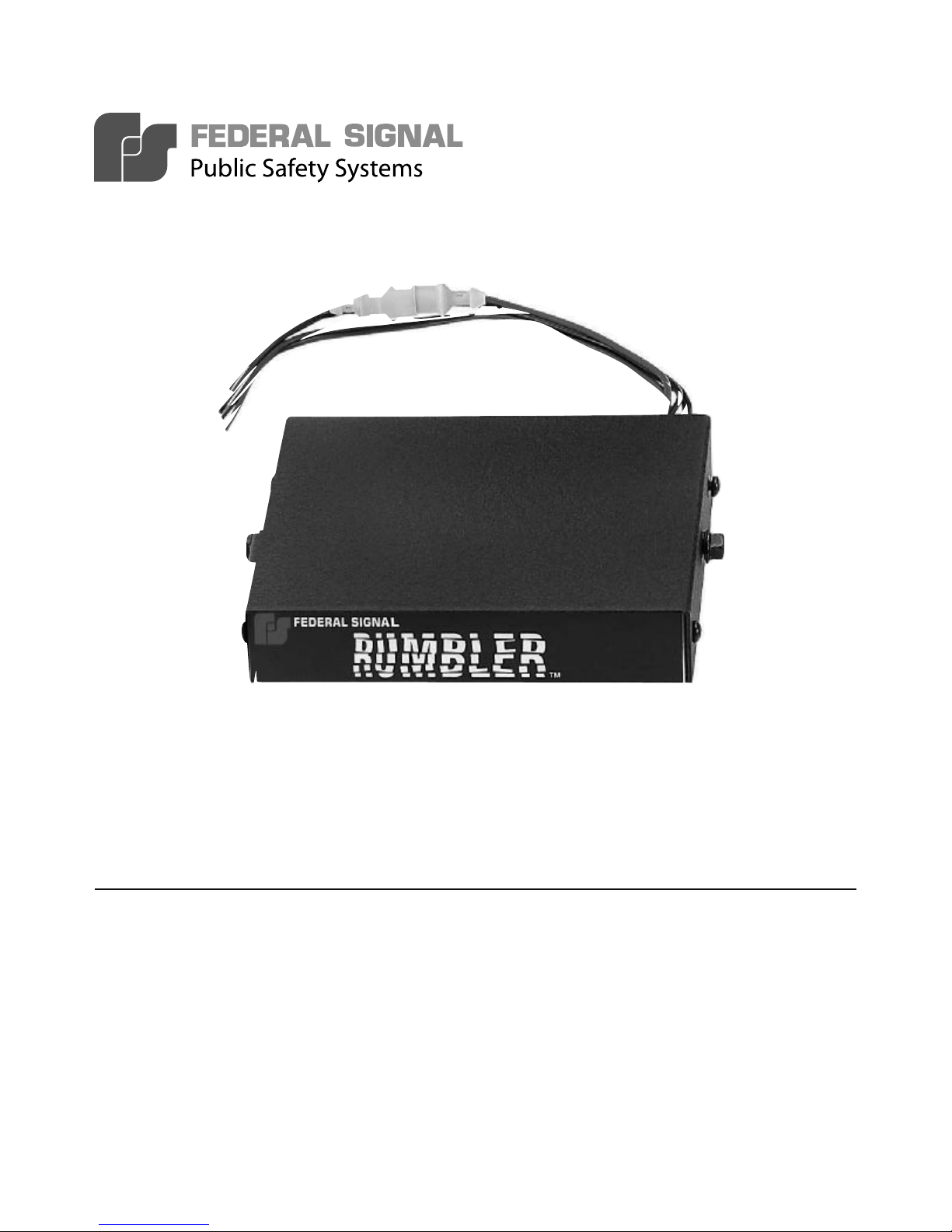
Low Frequency Siren Amplier
2562420B
REV. B2 0714
Printed in U.S.A.
Model Rumbler® 2
Installation and
Operation Instructions

blank page

Contents
Introduction .........................................................................................................................................1
Features ..................................................................................................................................................... 1
i
Applications
Safety Message to Installers of Federal Signal Light and Sound Systems ..................................2
Unpacking and Inspecting the
Mounting the
Wiring the
.............................................................................................................................................. 1
RumbleR 2 .........................................................................................3
RumbleR 2 in the Vehicle ..............................................................................................3
RumbleR 2 in the Vehicle ...................................................................................................5
Connecting a Speaker ...............................................................................................................................5
Connecting the Input Leads
Connecting the Activation Input
Connecting Power
Setting the 8–60 Second Timer .........................................................................................................7
Testing the
Safety Message to Operators of Federal Signal Light and Sound Systems
RumbleR 2 After Installation ............................................................................................ 8
..................................................................................................................................... 6
...................................................................................................................... 5
............................................................................................................... 6
.................................9
Operating the
Safety Message to Personnel Servicing Federal Signal Electronic Sirens.................................10
Getting Parts and Service for the
RumbleR 2 ...................................................................................................................10
RumbleR 2 .................................................................................. 11

ii
Contents

Introduction
The Federal Signal RumbleR® 2 Low Frequency Siren Amplier incorporates the latest solid-state designs
for superior reliability and sound quality. The RumbleR 2 uses the output of a standard emergency vehicle
siren and synthesizes a low frequency signal. It then amplies that signal to drive a Federal Signal Low
Frequency Siren Speaker.
The amplier’s adjustable 8–60 second timer enables the tone to sound for the selected interval and then
automatically turns it off. The result is a highly-effective backup emergency tone, especially when crossing
hazardous trafc intersections.
RumbleR 2 is designed for use in negative-grounded vehicles with 12-volt electrical systems. It can be
The
mounted in a variety of positions.
Features
• Economical small and compact—mounts virtually anywhere.
• Easy to operate—horn ring activation.
• High reliability—advanced circuitry and FET design.
1
• Output short-circuit protected—replaceable fuse protection.
Applications
• Police vehicles
• Fire chief vehicles
• Volunteer emergency vehicles
Table 1: RumbleR 2 specications
Input voltage 9 Vdc to 15 Vdc
Operating input current 12 A maximum
Polarity Negative-grounded systems only
Standby current 0.025 A nominal
Operating temperature rang –30º C to +65º C
Frequency range 182 to 400 Hz
Output voltage 64 V (nominal) peak-to-peak
Output Power 80 W
Dimensions 1.3" H (3.3 cm) x 6.3 " L (16.0 cm) x 5.7 "(14.5 cm)
Shipping Weight 3 lb (1.4 kg)

2
Safety Message to Installers of Federal Signal Light and Sound Systems
Safety Message to Installers of Federal Signal Light and Sound Systems
The lives of people depend on your safe installation of Federal Signal products. It is important to
read and follow all instructions shipped with the products. In addition, listed below are some other
important safety instructions and precautions you should follow.
Before Installation
Qualications
• To properly install an electronic siren: you must have a good understanding of automotive electrical procedures and systems along with prociency in the installation and service of safety warning
equipment.
Sound Hazards
• Your hearing and the hearing of others, in or close to your emergency vehicle, could be damaged
by loud sounds. This can occur from short exposures to very loud sounds or from longer exposures
to moderately loud sounds. For hearing and conservation guidance, refer to federal, state, or local
recommendations. OSHA Standard 1910.95 offers guidance on “Permissible Noise Exposure.”
• All effective sirens and horns produce loud sounds, which may, in certain situations, cause perma-
nent hearing loss. You should minimize your exposure times and wear suitable hearing protection.
During Installation
• DO NOT connect this system to the vehicle battery until ALL other electrical connections are
made, mounting of all components is complete, and you have veried that no shorts exist.
• Be sure the siren amplier and speaker in your installation have compatible wattage ratings.
• For this electronic siren to function properly, the ground connection must be made to the NEGA-
TIVE battery terminal.
• Sound output will be severely reduced if any objects are in front of the speaker. If maximum sound
output is required for your application, you should ensure that the front of the speaker is clear of
any obstructions.
• Install the speaker in a location which provides maximum signaling effectiveness and minimizes
the sound reaching the vehicle’s occupants.
• Never attempt to install aftermarket equipment which connects to the vehicle wiring, without reviewing a vehicle wiring diagram - available from the manufacturer. Insure that your installation
will not affect vehicle operation or mandated safety functions or circuits.
• DO NOT install equipment, route wiring or cord in the deployment path of an airbag.
• If a vehicle seat is temporarily removed, verify with the vehicle manufacturer if the seat needs to
be recalibrated for proper airbag deployment.
• Locate the siren so the vehicle controls can be operated safely.
• When drilling into a vehicle structure, be sure that both sides of the surface are clear of anything
that could be damaged.
• If wiring is shorted to vehicle frame, high current conductors can cause hazardous sparks resulting
in electrical res or ying molten metal.

Unpacking and Inspecting the Rumbler 2
After Installation
• After installation, test the electronic siren and speaker system to ensure that it is operating properly.
• Test all vehicle functions, including horn operation and vehicle light systems, to ensure proper op-
eration. Ensure that installation has not affected vehicle operation or changed any mandated safety
function or circuit.
• After testing is complete, provide a copy of these instructions to the instructional staff and all op-
erating personnel.
• File these instructions in a safe place and refer to them when maintaining and/or reinstalling the
product.
Failure to follow all safety precautions and instructions may result in property damage, serious injury, or death.
Unpacking and Inspecting the RumbleR 2
After unpacking the RumbleR 2, examine it for damage that may have occurred in transit. If the equipment
has been damaged, le a claim immediately with the carrier stating the extent of damage. Carefully check
all envelopes, shipping labels, and tags, and ensure that the parts listed in Table 2 are contained in the pack-
ing carton before removing or destroying them.
3
Table 2: Parts list
Qty. Description
1 Amp,
2 Bracket, Mounting
2 1/4-20 x 1/2, Self Tap, Hex
2 3/8, Washer, Star
RumbleR 2
The installation requires installer-supplied four 10-32 x 3/4 hex head screws, 10-32 split lock washers,
and 10-32 hex nuts. An additional installer-supplied 15 A fuse and in-line fuse holder are also required for
fusing the Rumbler 2 at the power source. The amplier is activated through the horn ring circuit or an
installer-supplied momentary switch.
Mounting the RumbleR 2 in the Vehicle
USE ONLY AS A SUPPLEMENTAL SIREN
The RumbleR 2 is intended as a supplemental warning for use at intersections and other areas close to
the emergency vehicle. You must continue to use the regular siren in connection with the RumbleR 2.
Failure to follow this warning can reduce the effectiveness of the siren system and cause serious injury.
AIRBAG DEPLOYMENT
Do not install equipment or route wiring in the deployment of an airbag. Failure to observe this warning
will reduce the effectiveness of the airbag or potentially dislodge the equipment, causing serious injury.

4
Mounting the Rumbler 2 in the Vehicle
UNIT REQUIRES VENTILATION
The RumbleR 2 needs to radiate heat. Do not install it in an area where it cannot dissipate heat into
the air. Do not mount it near a heater duct or under the vehicle’s hood.
RumbleR 2 has two mounting brackets that mount it in a variety of positions. The amplier has no user-
The
operated controls, so it can be mounted in the trunk or other concealed area in the vehicle.
To mount the
RumbleR 2 in a vehicle:
1. Select a mounting location.
2. Use a mounting bracket as a template and scribe two drill-position marks 7 inches apart at the selected
mounting location.
DRILLING PRECAUTIONS
Before drilling holes, check the area into which you plan to drill to ensure you do not damage vehicle components while drilling. All drilled holes should be deburred and all sharp edges should be
smoothed. All wires going through drilled holes should be protected by a grommet or convolute/
split-loom tubing.
3. Drill four mounting holes at the position marks.
4. Secure the mounting brackets to the surface with installer-supplied 10-32 x 3/4 hex head screws, 10-32
split lock washers, and 10-32 hex nuts (four of each).
5. Secure the amplier to the mounting brackets with the 1/4-20 x 1/2 hex head screws and 3/8" star
washers just enough so you can adjust its position (Figure 1).
6. Adjust the amplier to the position you want and tighten the screws.
BRACKET, MOUNTING
(2 PLACES)
WASHER, STAR, 3/8"
(2 PLACES)
SCREW, HEX, 1/4"-20 X 1/2" LENGTH
(2 PLACES)
Figure 1: Front view of RumbleR 2 with mounting hardware
290A6108

Wiring the Rumbler 2 in the Vehicle
Wiring the RumbleR 2 in the Vehicle
FIRE HAZARD
If shorted to the vehicle frame, high current conductors can cause hazardous sparks resulting in
electrical res or molten metal.
DO NOT connect this system to vehicle battery until ALL other electrical connections are made and
mounting of all components is complete. Verify that no short circuits exist before connecting to the
positive (+) battery terminal.
Failure to follow this warning can cause a re and may result in serious injury or death to you or
others.
DRILLING PRECAUTIONS
Before drilling holes, check the area into which you plan to drill to ensure you do not damage vehicle
components while drilling. All drilled holes should be de-burred and all sharp edges should be smoothed.
All wires going through drilled holes should be protected by a grommet or convolute/split-loom tubing.
5
Connecting a Speaker
USE ONLY WITH MODEL 751000 SPEAKER
The RumbleR 2 siren amplier is designed to operate only with the Model 751000 RumbleR
speaker. Connecting the RumbleR 2 to a standard siren speaker will damage the speaker.
A speaker is not included as part of the electronic siren amplier. Mounting instructions for the Model
751000 Low Frequency Speaker is included with the speaker.
The power and speaker cables are included on the siren. All wires must be connected as shown in Figure 2 on page 6 and in Figures 3 on page 7.
Use 18 AWG wire to connect the amplier’s speaker leads (clear zip cord) to the speaker. Ensure that
exposed connections are properly insulated.
Connecting the Input Leads
CONNECT INPUT LEADS PROPERLY
Failure to connect the input leads as shown in Figure 3 on page 7 could result in damage to the
vehicle’s main emergency siren.
Use 18 AWG wire to connect the input leads (black zip cord) in series with one of the speaker leads of
the emergency vehicle’s main siren. See Figure 3 for the wiring diagram.
Use 18 AWG wire to connect the brown input lead to the other speaker lead of the emergency vehicle’s
main siren. See Figure 3 for the wiring diagram.

6
Wiring the Rumbler 2 in the Vehicle
Connecting the Activation Input
Use 22 AWG wire to connect the white activation lead to the vehicle’s horn ring circuit or user sup-
plied momentary switch.
NOTE: The
RumbleR 2 only activates by placing the white activation lead to ground. If activation is
required from a 12-volt signal, an installer-supplied relay or a Federal Signal UPKM-3 Module must
be used. The 12-volt signal will energize the relay, and the relay contact will place the white activation
lead to ground.
Connecting Power
The RumbleR 2 operates only from 12-volt NEGATIVE-grounded vehicle electrical system. There-
fore, before making any electrical connections, determine the polarity of the vehicle’s electrical sys-
tem ground.
BATTERY DRAIN
The Rumbler 2 system does not have an on-off switch. If power for the Rumbler 2 is obtained
directly from the vehicle battery, it draws approximately 0.20 Ah per day in standby mode. If you
are connecting the Rumbler 2 to the switched side of the ignition circuit, make sure the circuit has
enough current capacity to handle the additional 10 A (approx.) load.
FUSE AMPLIFIER AT 12 V SOURCE
Damage to the RumbleR 2 will occur if it is not properly fused. Ensure that the supplied in-line fuse
holder and 15 A fuse are installed in the red power lead. The RumbleR 2 should also be fused with
a user supplied 15 A fuse at the 12-volt source.
1. Use a 14 AWG or heavier wire to connect the amplier’s black ground lead to the vehicle bat-
tery’s negative terminal (–NEG) or ground lug (Figure 2).
2. Use a 14 AWG or heavier wire to connect the amplier’s red lead to the selected 12-volt source.
CURRENT INPUT LEADS
(BLACK ZIPCORD)
SIGNAL INPUT LEAD(
GROUND LEAD (BLACK WIRE)
FUSE HOLDER
290A6109C
(BROWN WIRE)
SPEAKER LEADS
(CLEAR ZIPCORD)
POSITIVE LEAD (RED WIRE)

RUMBLER AMPLIFIER
Setting the 8–60 Second Timer
Figure 2: Rear view of RumbleR 2 with leads
CLEAR ZIP CORD RUMBLER SPEAKERS
WHITE HORN RING OR
MOMENTARY SWITCH
F1 15 AMP
RED VEHICLE BATTERY
BROWN
BLACK ZIP CORD
7
MAIN SIREN AMPLIFIER
MAIN SIREN
SPEAKER('S)
290A6482B
BLACK GROUND
BLACK ZIP CORD RIBED
CUT WIRE
CAUTION:
CONNECTING THE BLACK ZIP CORD IN PARALLEL
WITH THE MAIN SIREN SPEAKER COULD DAMAGE THE MAIN VEHICLE SIREN AMPLIFIER
X
X
Figure 3: Rumbler 2 wiring diagram
Setting the 8–60 Second Timer
SOUND HAZARD
The RumbleR 2 increases close-proximity warning effectiveness by generating siren signals that better
penetrate a vehicle’s interior. These signals also may increase sound levels in the operator’s vehicle,
and may increase noise exposure to the operator. The amount of this increase will vary based upon
the length of time operators are exposed to noise from emergency operation, the vehicle in which the
RumbleR 2 is installed, and other factors.
To protect the operator from sound-exposure hearing loss, you should measure the sound levels in
the vehicle and calculate permissible exposure times. One source of permissible exposure times is the
federal OSHA regulations in section 1910.95.
The amplier’s 8-60 second timer is factory-set for a default time of 8 seconds. After assessing sound
levels in the operators’ compartment, you must adjust the timer on the interface board inside the
amplier to limit the operating time of the amplier based upon the expected usage through a work
shift. You should also be sure your operators heed all other warnings associated with the use of sirens,
and provide and require the use of hearing protection, if appropriate, based on your particular exposure levels and conditions of use. If you operate the
operator noise exposures, set it for the shortest amount of time possible and require the use of hearing
protection devices.
For more information on sound exposure, refer to the warnings in “Safety Messages to Operators of
Federal Signal Light and Sound Systems” on page 9 and in “Operating the Rumbler 2” on page 10.
RumbleR 2 before you can make an assessment of

8
Testing the Rumbler 2 After Installation
Failure to follow this warning may result in hearing damage to operators and passengers.
To set the timer:
1. Remove the RumbleR 2 from the mounting brackets.
2. Locate the slot on the left side of the top cover.
3. See Figure 4. Rotate the rotary dip switch until the LED indicator displays the desired time interval.
NOTE: The RumbleR 2 system will not operate if the vehicle’s main siren speaker is not functioning
properly.
ROTARY
LEDs
DIP SW
8 SEC
15 SEC
22 SEC
30 SEC
37 SEC
45 SEC
52 SEC
60 SEC
290A6483
Figure 4: Timer dip switch
4. Activate the vehicle’s main siren and the RumbleR 2.
5. Check the sound exposure time and make further adjustments, if necessary.
6. When nished, place the cover on the RumbleR 2 and tighten the screws.
7. Reinstall the RumbleR 2 in the brackets.
Testing the RumbleR 2 After Installation
SOUND HAZARD
All effective sirens and horns produce loud sounds (120 dB) that may cause permanent hearing loss.
Always minimize your exposure to siren sound and wear hearing protection. Do not sound the siren
indoors or in enclosed areas where you and others will be exposed to the sound.
After installation, test the electronic siren to ensure that it is operating properly. The siren is designed to
blow the fuse under reverse polarity conditions. If the fuse fails when power is supplied, check and correct
the power lead wiring. Install a 15 A in-line fuse and re-apply power.

Safety Message to Operators of Federal Signal Light and Sound Systems
After testing is complete, provide a copy of this manual to all operating personnel.
Safety Message to Operators of Federal Signal Light and Sound Systems
The lives of people depend on your safe operation of Federal Signal products. It is important to read
and follow all instructions shipped with the products. In addition, listed below are some other important safety instructions and precautions you should follow.
Qualications
• To properly use an electronic siren and speaker(s) you must have a good understanding of general
vehicle operation, a high prociency in the use of safety warning equipment, and thorough knowledge of state and federal UNIFORM TRAFFIC CODES.
Sound Hazards
• Your hearing and the hearing of others, in or close to your emergency vehicle, could be damaged
by loud sounds. This can occur from short exposures to very loud sounds, or from longer exposures
to moderately loud sounds. For hearing conservation guidance, refer to federal, state, or local recommendations. OSHA Standard 1910.95 offers guidance on “Permissible Noise Exposure.”
• All effective sirens and horns produce loud sounds which may, in certain situations, cause permanent
hearing loss. You should minimize your exposure times and wear suitable hearing protection.
9
Sound Limitations
• Maximum sound output will be severely reduced if any objects are in front of the speaker. If your
installation has obstructions in front of the speaker, drive even more cautiously.
• Frequently inspect the speaker to ensure that it is clear of any obstruction, such as mud or snow,
which will reduce maximum sound output.
Signaling Limitations
• Be aware that the use of your visual and audible signaling devices do not give you the right to force
your way through trafc. Your emergency lights, siren, and actions are REQUESTING the rightof-way.
• Although your warning system is operating properly, it may not alert everyone. People may not
hear, see, or heed your warning signal. You must recognize this fact and continue driving cau-
tiously.
• Situations may occur which obstruct your warning signal when natural or man-made objects are
between your vehicle and others, such as when you raise your hood or trunk lid. If these situations
occur, be especially careful.
Driving Limitations
• At the start of your shift, you should ensure that the light/sound system is securely attached to the
vehicle and operating properly.
• If the unique combination of emergency vehicle equipment installed in your vehicle has resulted
in the light/siren controls being installed in a position that does not allow you to operate them by
touch only, OPERATE CONTROLS ONLY WHILE YOUR VEHICLE IS STOPPED.
• If driving conditions require your full attention, you should avoid operating the light/siren controls
while the vehicle is in motion.
Continuing Education
• File these instructions in a safe place and refer to them periodically. Give a copy of these instruc-
tions to new recruits and trainees.

10
Operating the Rumbler 2
Failure to follow these safety precautions may result in property damage, serious injury, or death.
Operating the RumbleR 2
The RumbleR 2 has no user switches on the amplier unit. Refer to your standard siren system manual for
instructions on using your system.
RumbleR 2 system operates in conjunction with your standard vehicle siren. You activate the Rum-
Your
bleR 2 sound by pressing the horn switch on your steering wheel. The RumbleR 2 turns off automatically
based on a preset time.
SOUND HAZARD
If the RumbleR 2 system does not shut off automatically, you should have your system checked. Over
exposure to RumbleR 2 sound may cause hearing loss. This overexposure can occur if your system is
not shutting off automatically.
SOUND HAZARD
The sound generated by the RumbleR 2 penetrates your vehicle as well as other vehicles. To protect
yourself from hearing loss due to the sound produced by RumbleR 2, you should use the it only for
intersection applications where you need extra-close proximity penetration.
Safety Message to Personnel Servicing Federal Signal Electronic Sirens
The lives of people depend on your safe servicing of products. It is important to read and follow all
instructions shipped with the products. In addition, listed below are some other safety instructions
and precautions you should follow.
• Read and understand all instructions in this manual before servicing the electronic siren.
• To properly service an electronic siren: you must have a good understanding of automotive electri-
cal procedures and systems, along with prociency in the installation and service of safety warning
equipment.
• Electronic circuit repairs must be performed by a qualied and competent electronic technician.
• Your hearing and the hearing of others, in or close to your emergency vehicle, could be damaged
by loud sounds. This can occur from short exposures to very loud sounds or from longer exposures
to moderately loud sounds. For hearing conservation guidance, refer to federal, state, or local recommendations. OSHA Standard 1910.95 offers guidance on “Permissible Noise Exposure.”
• All effective sirens and horns produce loud sounds, which may cause, in certain situations, permanent
hearing loss. You should take appropriate safety precautions such as wearing hearing protection.
• DO NOT connect this system to the positive terminal of the battery until servicing is complete, and
you have veried that there are no short circuits to ground.
• In order for the electronic siren to function properly, the ground connection must be made to the
NEGATIVE battery terminal.
• After repair, test the electronic siren and speaker system to ensure that it is operating properly.
Failure to follow all safety precautions and instructions may result in property damage, serious in-

Getting Parts and Service for the Rumbler 2
jury, or death.
Getting Parts and Service for the RumbleR 2
The factory can and will service your equipment or assist you with technical problems that cannot be
handled satisfactorily and promptly locally.
Servicing, other than cosmetic features, should be performed by a qualied Federal Signal service center.
RumbleR 2 is not working properly, disconnect all electrical connections. Remove the it from the
If the
mounting bracket. Send it to the nearest authorized service center or the Federal Signal Service Department.
After servicing is complete, perform a test of all functions to ensure the your siren system is operating
properly.
Communications and shipments should be addressed to either of these service locations:
Service Department Service Department
FS/Unitrol Federal Signal Corporation
1108 Raymond Way 2645 Federal Signal Drive
Anaheim, CA 92801 University Park, IL 60466
714-871-3336 800-433-9132
800-854-3375 E-mail: empserviceinfo@fedsig.com
11

2645 Federal Signal Drive, University Park, IL 60484-3167
Tel.: (800) 264-3578 • Fax: (800) 682-8022
www.fedsig.com
© 2012 Federal Signal Corporation
 Loading...