

Federal Signal Corporation PVS220W-24, PVS220W-48, PVS240W-24, PVS240W-48 Installation Manual
Solar Power Systems
Models: PVS220W-24, PVS220W-48,
PVS240W-24, and PVS240W-48
255379
Rev. E3 0917
Printed in U.S.A.
© Copyright 2017 Federal Signal Corporation
Installation Manual

Limited Warranty
This product is subject to and covered by a limited warranty,
a copy of which can be found at www.fedsig.com/SSG-Warranty.
A copy of this limited warranty can also be obtained by written
request to Federal Signal Corporation, 2645 Federal Signal Drive,
University Park, IL 60484, email to info@fedsig.com or
call +1 708-534-3400.
This limited warranty is in lieu of all other warranties, express or
implied, contractual or statutory, including, but not limited to the
warranty of merchantability, warranty of tness for a particular
purpose and any warranty against failure of its essential purpose.
2645 Federal Signal Drive
University Park, Illinois 60484-3617
www.fedsig.com
Customer Support 800-548-7229 • +1 708 534-3400
Technical Support 800-524-3021 • +1 708 534-3400

Contents
Safety Messages..................................................................................................................................... 5
General Description ............................................................................................................................... 8
Required Equipment ........................................................................................................................... 8
Weight................................................................................................................................................. 8
Installation Instructions ......................................................................................................................... 9
Installing the Solar Panel Bracket ....................................................................................................... 9
Side Pole Installation ................................................................................................................... 9
Top-of-Pole Installation ............................................................................................................. 14
Power Supply and Wiring .................................................................................................................... 16
Power Supply ................................................................................................................................... 16
Wiring the 48 V Junction Box ........................................................................................................... 16
Wiring the 24 V Junction Box (55 W Modules) ................................................................................. 17
Wiring the 24 V Junction Box (110 W Modules, three conductors) .................................................. 20
Wiring the Junction Box for 24 V (110 W Modules, four-wire) .......................................................... 21
Getting Service ..................................................................................................................................... 24
Tables
Table 1 Required Tools .......................................................................................................................... 8
Table 2 Side Pole Mount ........................................................................................................................ 8
Table 3 Top-of-Pole Mount ..................................................................................................................... 9
Installation Manual
3

Figures
Figure 1 Placement of 55 W Module (Top View) .................................................................................11
Figure 2 Placement of 60 W Module (Top View) ................................................................................ 12
Figure 3 Side Pole Mount (55 W or 60 W Modules) ........................................................................... 13
Figure 4 Side Pole Mount (110 W Modules) ....................................................................................... 14
Figure 5 Top-of-Pole Mount ................................................................................................................. 15
Figure 6 Module Wiring (back view) ................................................................................................... 18
Figure 7 Wiring PVS220W Systems .................................................................................................... 19
Figure 8 Wiring PVS240W Systems .................................................................................................... 20
Figure 9 Module Wiring 110 W Panels ................................................................................................ 22
Figure 10 Wiring PVS220W Systems .................................................................................................. 23
Figure 11 Module 110 W Placement .................................................................................................... 24
Figure 12 Final Assembly Solar Bracket 55 W or 60 W (4 Panel) ..................................................... 25
Figure 13 Final Assembly Solar Bracket Side Mount 110 W ............................................................ 26
Figure 14 Final Assembly Solar Bracket Top-of-Pole Mount 110 W (2 Panel) ................................ 27
Figure 15 DCB and DCFCB Solar Wiring ............................................................................................ 28
Figure 16 DCFCTB Solar Wiring .......................................................................................................... 29
Figure 17 One-Way Solar UltraVoice Wiring Diagram ...................................................................... 30
Figure 18 Two-Way Solar UltraVoice Wiring Diagram ...................................................................... 31
Figure 19 Hawaii UltraVoice Wiring Diagram ..................................................................................... 32
Figure 20 Solar Assembly for the UltraVoice ..................................................................................... 33
Figure 21 Solar Assembly for the DC Series Siren Control System ................................................ 34
4
Solar Power Systems

Safety Messages
It is important to follow all instructions shipped with this product. This device
is to be installed by trained personnel who are thoroughly familiar with the
country electric codes and will follow these guidelines as well as local codes.
Listed below are important safety instructions and precautions you should follow.
Important Notice
Federal Signal reserves the right to make changes to devices and specications detailed in
the manual at any time in order to improve reliability, function or design. The information
in this manual has been carefully checked and is believed to be accurate; however, no
responsibility is assumed for any inaccuracies.
Publications
Federal Signal recommends the following publications from the Federal Emergency
Management Agency for assistance with planning an outdoor warning system:
• The “Outdoor Warning Guide” (CPG 1-17)
Safety Messages
• “Civil Preparedness, Principles of Warning” (CPG 1-14)
• FEMA-REP-1, Appendix 3 (Nuclear Plant Guideline)
• FEMA-REP-10 (Nuclear Plant Guideline).
Planning
• If suitable warning equipment is not selected, the installation site for the siren
is not selected properly or the siren is not installed properly, it may not produce
the intended optimum audible warning. Follow Federal Emergency Management
Agency (FEMA) recommendations.
• If sirens are not activated in a timely manner when an emergency condition
exists, they cannot provide the intended audible warning. It is imperative that
knowledgeable people, who are provided with the necessary information, are
available at all times to authorize the activation of the sirens.
• When sirens are used out of doors, people indoors may not be able to hear the
warning signals. Separate warning devices or procedures may be needed to
effectively warn people indoors.
• The sound output of sirens is capable of causing permanent hearing damage. To
prevent excessive exposure, carefully plan siren placement, post warnings, and
restrict access to areas near sirens.
• Activating the sirens may not result in people taking the desired actions if those to
be warned are not properly trained about the meaning of siren sounds. Siren users
should follow FEMA recommendations and instruct those to be warned of correct
actions to be taken.
Installation Manual
5

Safety Messages
• After installation, service, or maintenance, test the siren system to conrm
• If future service and operating personnel do not have these instructions to refer
Installation and Service
• Electrocution or severe personal injury can occur when performing various
that it is operating properly. Test the system regularly to conrm that it will be
operational in an emergency.
to, the siren system may not provide the intended audible warning and service
personnel may be exposed to death, permanent hearing loss, or other bodily
injury. File these instructions in a safe place and refer to them periodically. Give a
copy of these instructions to new recruits and trainees. Also give a copy to anyone
who is going to service or repair the siren.
installation and service functions such as making electrical connections, drilling
holes, or lifting equipment. Therefore only experienced electricians should install
this product in accordance with national, state and any other electrical codes
having jurisdiction. Perform all work under the direction of the installation or
service crew safety foreman.
• The sound output of sirens is capable of causing permanent hearing damage.
To prevent excessive exposure, carefully plan siren placement, post warnings
and restrict access to areas near the sirens. Sirens may be operated from remote
control points. Whenever possible, disconnect all siren power including batteries
before working near the siren.
• After installation or service, test the siren system to conrm that it is operating
properly. Test the system regularly to conrm that it will be operational in an
emergency.
• If future service personnel do not have these warnings and all other instructions
shipped with the equipment to refer to, the siren system may not provide the
intended audible warning and service personnel may be exposed to death,
permanent hearing loss, or other bodily injury. File these instructions in a safe
place and refer to them periodically. Give a copy of these instructions to new
recruits and trainees. Also, give a copy to anyone who is going to service or repair
the sirens.
Operation
Failure to understand the capabilities and limitations of your siren system could result in
permanent hearing loss, other serious injuries or death to persons too close to the sirens
when you activate them or to those you need to warn. Carefully read and thoroughly
understand all safety notices in this manual and all operations-related-items in all
instruction manuals shipped with equipment. Thoroughly discuss all contingency plans
with those responsible for warning people in your community, company, or jurisdiction.
6
Solar Power Systems

Safety Messages
Read and understand the information contained in this manual before
attempting to install or service the siren.
Solar modules generate DC electricity when exposed to light. Exposure
to this voltage can result in serious injury or even death. Follow all safety
precautions.
To stop production of electricity, cover panel surfaces with opaque material
while working on system. Avoid touching terminals and/or wire ends until
connections are made.
Pay careful attention to the notices located on the equipment.
Installation Manual
7
General Description
General Description
This manual describes how to install the Solar Power Systems.
The Solar Power Systems provide an all inclusive solar powering options for all outdoor
sirens. Solar powering of batteries is an efcient and economical method of powering
remote sirens, alerting, or control equipment. Applications include, but are not limited to,
remote tsunami sirens, muster stations, and tornado sirens.
The PVS220W-24 and PVS220W-48 provide 220 W of power for charging of batteries in
24 or 48 Vdc applications. The PVS240W-24 and PVS240W-48 provide 240 W of power
for charging of batteries in 24 or 48 Vdc applications. These systems are equipped with
solar regulators for accurate control, protection, and monitoring of the solar panels. These
kits use four 55 W highly efcient solar panels, each with junction boxes to allow ease of
wiring.
The mounting hardware is aluminum for light weight and high strength, able to withstand
wind loads up to 170 mph. The kit includes thirty feet of cable to allow wiring from the
panels to the Battery Cabinet. The solar regulators support gel, sealed or ooded batteries
with temperature compensation to extend battery life and improve system performance.
Federal Signal determines the proper direction and tilt for each solar application based on
location. Federal Signal recommends gel batteries for solar applications.
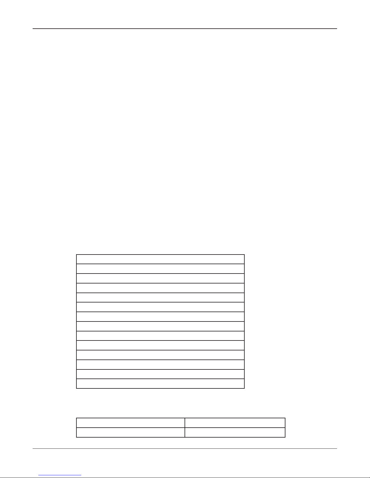
Required Equipment
You need the following equipment.
Table 1 Required Tools
Large at head screwdriver
Medium at head screwdriver
Narrow (3/16-in) at head screwdriver
Medium cross head screwdriver
Socket driver set with 7/16-in, 9/16-in and 3/4-in sockets
7/16-in open end wrench
9/16-in open end wrench
Adjustable wrench
Wire cutters
Needle nose pliers
Wire strip and crimp tool
Electric drill with 1/4-in drill bit
Utility knife
Measuring tape
Weight
Table 2 Side Pole Mount
Net Weight 115 pounds (52 kg)
Shipping Weight 153 pounds (69 kg)
8
Solar Power Systems

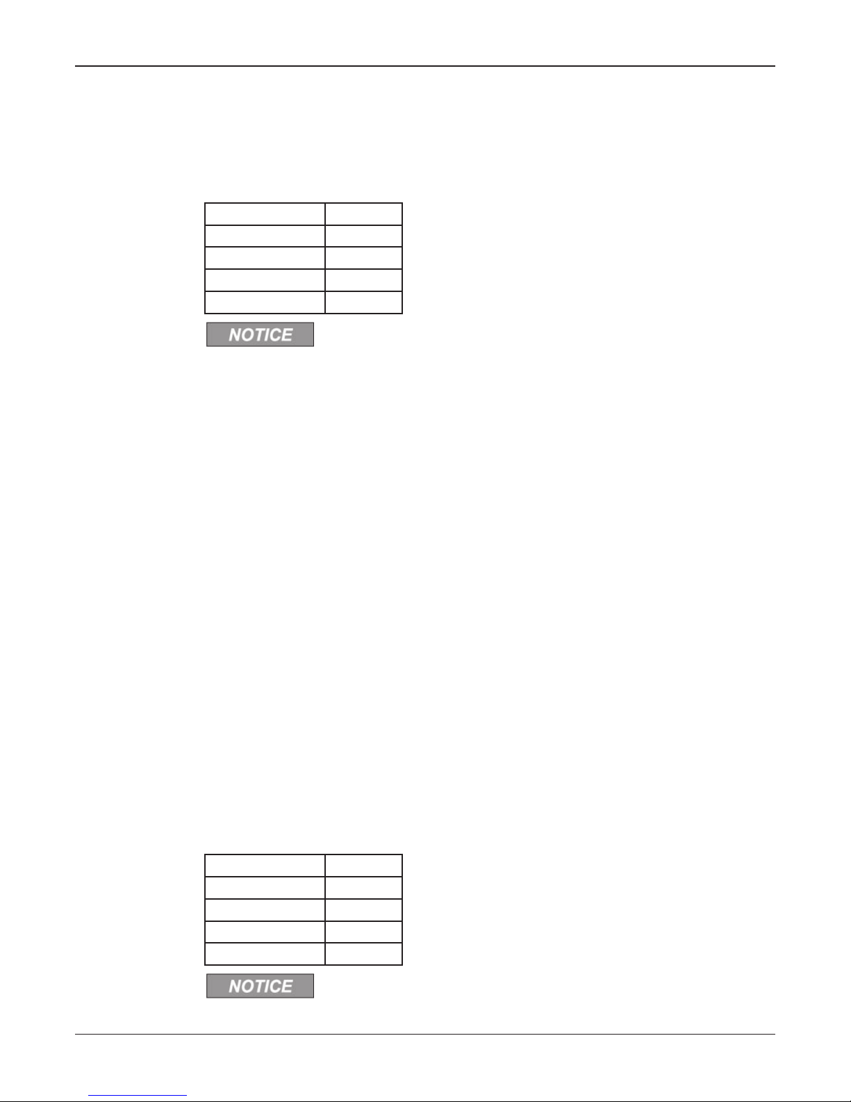
Table 3 Top-of-Pole Mount
Net Weight 112 pounds (51 kg)
Shipping Weight 150 pounds (68 kg)
Installation Instructions
Installing the Solar Panel Bracket
Electrocution or severe personal injury can occur when making electrical
connections, drilling holes, or lifting equipment. Therefore, installation should
be performed by experienced electricians in accordance with national and
local codes.
Most bracket installations are one of two types: Side Pole Mount or Top Pole Mount.
These two congurations make it possible to provide solar power in almost any situation.
If the installations in this manual are not suitable, it may be practical to modify one of the
congurations.
For best results, the solar modules must face true south. Consult FEMA CPG 1-17 and
CPG 1-14 and your local Federal Signal representative to properly place your outdoor
warning equipment.
Installation Instructions
Side Pole Installation
The bracket is typically mounted on a Class 2 utility pole (ANSI type wooden pole or
equivalent) with a minimum horizontal ground stress rating of 3,700 pounds (1678 kg).
Insure that soil loads will conform to this size utility pole.
NOTE: Certain soil conditions may require guying for the pole. Check with proper
building authorities.
To install a side pole mount solar bracket onto a wooden utility pole, do the following:
1. Uncrate and identify the various parts. You can use an empty box as a platform to
protect assembly and modules from damage.
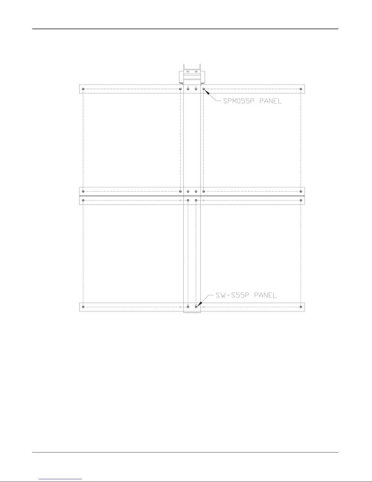
2. Place the solar modules face down with their junction boxes toward center for the
55 W and 60 W modules or toward top for the 110 W panels.
NOTE: 55 W modules come in two alternate sizes (See 55 W Module
Placement).
3. Assemble the solar bracket onto the solar modules per nal assembly drawing.
Apply thread locking compound to all fastening hardware to ensure secure
assembly.
4. Find the desired elevation on the pole. For best results, the solar modules must
face true south. Mark the eight mounting holes on the pole for the bracket.
5. Drill a 3/8-inch pilot hole at each of the locations. Drill each hole at least
3-1/2 inch deep.
Installation Manual
9
Installation Instructions
6. Using eight 1/2-inch stainless steel lag screws (minimum of 5 inches in length)
or two sections of ¾-inch wide stainless steel strapping, secure the solar bracket
onto the pole.
7. Locate your site and nd the latitude of your location. For the Northern
Hemisphere, add or set the tilt angle at the value specied in the following table.
Latitude Range Tilt Angle
90° to 60° 60°
60° to 25° +15°
25° to 20° +5°
20° to 0° 25°
Tilt angles are limited to a minimum of 25° and maximum of 60° degrees.
8. Find the vertical distance Y for your setup from the tilt angle charts.
For any other type of pole, such as a galvanized steel pole, install the side mount solar
bracket as follows:
1. Uncrate and identify the various parts. Use an empty box as a platform to protect
assembly and modules from damage.
2. Start by placing the solar modules face down with their junction boxes toward
center for the 55 W and 60 W modules or toward top for the 110 W panels.
NOTE: 55 W modules come in two alternate sizes (see Placement of 55 W
Module).
3. Assemble the solar bracket onto the solar modules per nal assembly drawing.
Apply thread locking compound to all fastening hardware to ensure secure
assembly.
4. Find the desired elevation on the pole. For best results, the solar modules must
face true south. Mark the two placement locations on the pole for the bracket.
5. Secure the solar bracket by clamping it onto the pole by using two sections of
¾-inch wide stainless steel strapping and the tilt angle charts.
6. Locate your site and nd the latitude of your location. For the Northern
Hemisphere, add or set the tilt angle at the following table.
Latitude Range Tilt Angle
90° to 60° 60°
60° to 25° +15°
25° to 20° +5°
20° to 0° 25°
Tilt angles are limited to a minimum of 25° and maximum of 60° degrees.
10
Solar Power Systems
Installation Instructions
7. Find the vertical distance Y for your setup from the tilt angle charts.
Figure 1 Placement of 55 W Module (Top View)
Installation Manual
11
 Loading...