

Federal Signal Corporation PVS220W-24, PVS220W-48, PVS240W-24, PVS240W-48 Installation Manual
Page 1
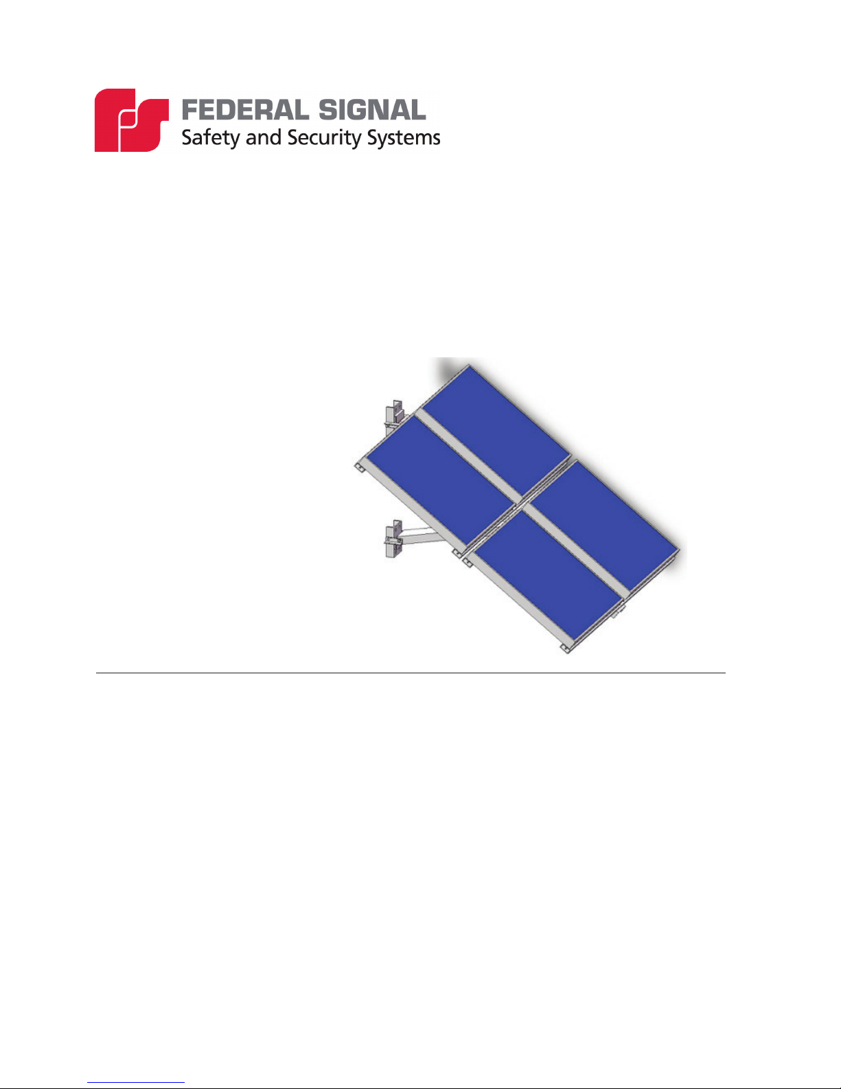
Solar Power Systems
Models: PVS220W-24, PVS220W-48,
PVS240W-24, and PVS240W-48
255379
Rev. E3 0917
Printed in U.S.A.
© Copyright 2017 Federal Signal Corporation
Installation Manual
Page 2

Limited Warranty
This product is subject to and covered by a limited warranty,
a copy of which can be found at www.fedsig.com/SSG-Warranty.
A copy of this limited warranty can also be obtained by written
request to Federal Signal Corporation, 2645 Federal Signal Drive,
University Park, IL 60484, email to info@fedsig.com or
call +1 708-534-3400.
This limited warranty is in lieu of all other warranties, express or
implied, contractual or statutory, including, but not limited to the
warranty of merchantability, warranty of tness for a particular
purpose and any warranty against failure of its essential purpose.
2645 Federal Signal Drive
University Park, Illinois 60484-3617
www.fedsig.com
Customer Support 800-548-7229 • +1 708 534-3400
Technical Support 800-524-3021 • +1 708 534-3400
Page 3

Contents
Safety Messages..................................................................................................................................... 5
General Description ............................................................................................................................... 8
Required Equipment ........................................................................................................................... 8
Weight................................................................................................................................................. 8
Installation Instructions ......................................................................................................................... 9
Installing the Solar Panel Bracket ....................................................................................................... 9
Side Pole Installation ................................................................................................................... 9
Top-of-Pole Installation ............................................................................................................. 14
Power Supply and Wiring .................................................................................................................... 16
Power Supply ................................................................................................................................... 16
Wiring the 48 V Junction Box ........................................................................................................... 16
Wiring the 24 V Junction Box (55 W Modules) ................................................................................. 17
Wiring the 24 V Junction Box (110 W Modules, three conductors) .................................................. 20
Wiring the Junction Box for 24 V (110 W Modules, four-wire) .......................................................... 21
Getting Service ..................................................................................................................................... 24
Tables
Table 1 Required Tools .......................................................................................................................... 8
Table 2 Side Pole Mount ........................................................................................................................ 8
Table 3 Top-of-Pole Mount ..................................................................................................................... 9
Installation Manual
3
Page 4

Figures
Figure 1 Placement of 55 W Module (Top View) .................................................................................11
Figure 2 Placement of 60 W Module (Top View) ................................................................................ 12
Figure 3 Side Pole Mount (55 W or 60 W Modules) ........................................................................... 13
Figure 4 Side Pole Mount (110 W Modules) ....................................................................................... 14
Figure 5 Top-of-Pole Mount ................................................................................................................. 15
Figure 6 Module Wiring (back view) ................................................................................................... 18
Figure 7 Wiring PVS220W Systems .................................................................................................... 19
Figure 8 Wiring PVS240W Systems .................................................................................................... 20
Figure 9 Module Wiring 110 W Panels ................................................................................................ 22
Figure 10 Wiring PVS220W Systems .................................................................................................. 23
Figure 11 Module 110 W Placement .................................................................................................... 24
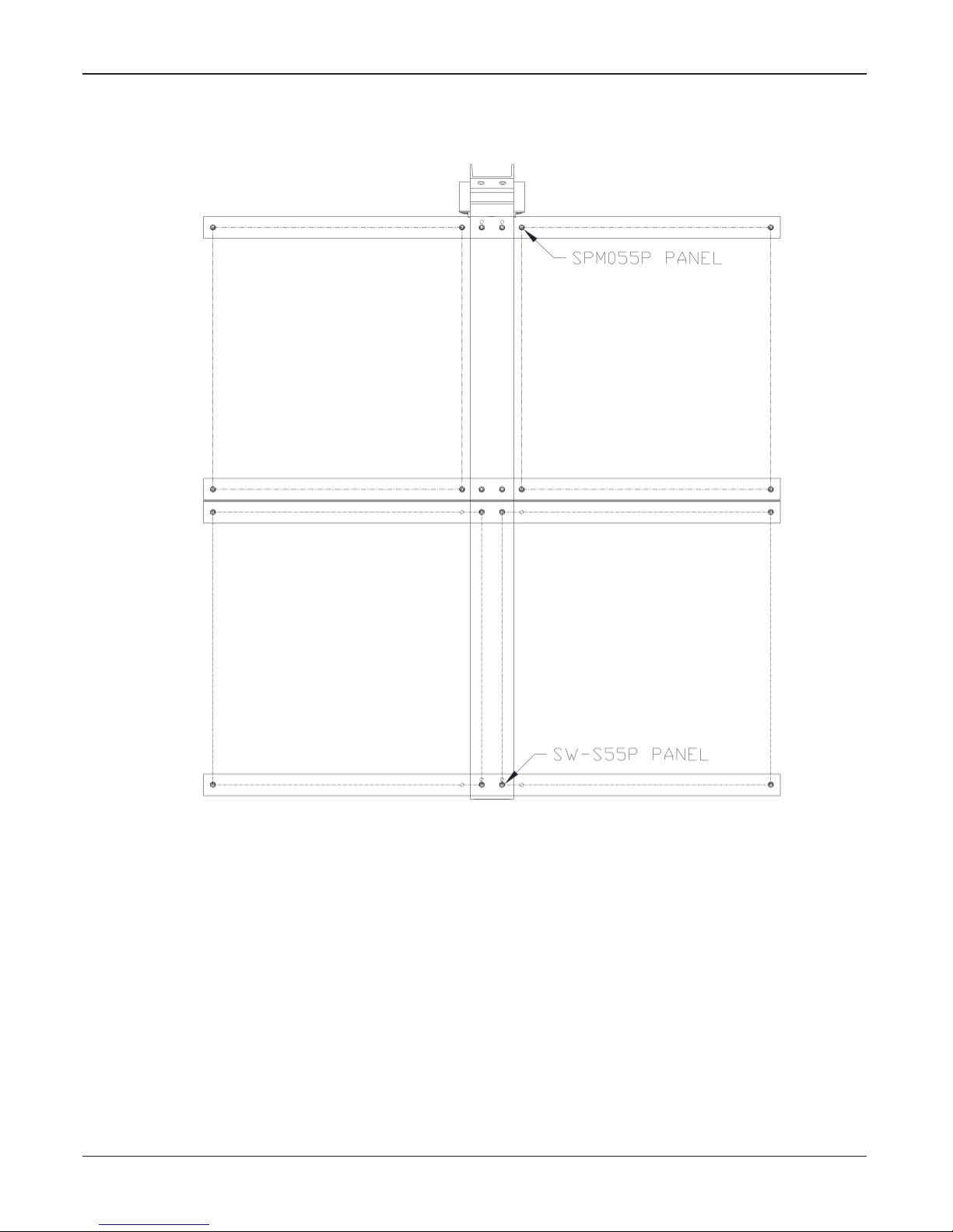
Figure 12 Final Assembly Solar Bracket 55 W or 60 W (4 Panel) ..................................................... 25
Figure 13 Final Assembly Solar Bracket Side Mount 110 W ............................................................ 26
Figure 14 Final Assembly Solar Bracket Top-of-Pole Mount 110 W (2 Panel) ................................ 27
Figure 15 DCB and DCFCB Solar Wiring ............................................................................................ 28
Figure 16 DCFCTB Solar Wiring .......................................................................................................... 29
Figure 17 One-Way Solar UltraVoice Wiring Diagram ...................................................................... 30
Figure 18 Two-Way Solar UltraVoice Wiring Diagram ...................................................................... 31
Figure 19 Hawaii UltraVoice Wiring Diagram ..................................................................................... 32
Figure 20 Solar Assembly for the UltraVoice ..................................................................................... 33
Figure 21 Solar Assembly for the DC Series Siren Control System ................................................ 34
4
Solar Power Systems
Page 5

Safety Messages
It is important to follow all instructions shipped with this product. This device
is to be installed by trained personnel who are thoroughly familiar with the
country electric codes and will follow these guidelines as well as local codes.
Listed below are important safety instructions and precautions you should follow.
Important Notice
Federal Signal reserves the right to make changes to devices and specications detailed in
the manual at any time in order to improve reliability, function or design. The information
in this manual has been carefully checked and is believed to be accurate; however, no
responsibility is assumed for any inaccuracies.
Publications
Federal Signal recommends the following publications from the Federal Emergency
Management Agency for assistance with planning an outdoor warning system:
• The “Outdoor Warning Guide” (CPG 1-17)
Safety Messages
• “Civil Preparedness, Principles of Warning” (CPG 1-14)
• FEMA-REP-1, Appendix 3 (Nuclear Plant Guideline)
• FEMA-REP-10 (Nuclear Plant Guideline).
Planning
• If suitable warning equipment is not selected, the installation site for the siren
is not selected properly or the siren is not installed properly, it may not produce
the intended optimum audible warning. Follow Federal Emergency Management
Agency (FEMA) recommendations.
• If sirens are not activated in a timely manner when an emergency condition
exists, they cannot provide the intended audible warning. It is imperative that
knowledgeable people, who are provided with the necessary information, are
available at all times to authorize the activation of the sirens.
• When sirens are used out of doors, people indoors may not be able to hear the
warning signals. Separate warning devices or procedures may be needed to
effectively warn people indoors.
• The sound output of sirens is capable of causing permanent hearing damage. To
prevent excessive exposure, carefully plan siren placement, post warnings, and
restrict access to areas near sirens.
• Activating the sirens may not result in people taking the desired actions if those to
be warned are not properly trained about the meaning of siren sounds. Siren users
should follow FEMA recommendations and instruct those to be warned of correct
actions to be taken.
Installation Manual
5
Page 6

Safety Messages
• After installation, service, or maintenance, test the siren system to conrm
• If future service and operating personnel do not have these instructions to refer
Installation and Service
• Electrocution or severe personal injury can occur when performing various
that it is operating properly. Test the system regularly to conrm that it will be
operational in an emergency.
to, the siren system may not provide the intended audible warning and service
personnel may be exposed to death, permanent hearing loss, or other bodily
injury. File these instructions in a safe place and refer to them periodically. Give a
copy of these instructions to new recruits and trainees. Also give a copy to anyone
who is going to service or repair the siren.
installation and service functions such as making electrical connections, drilling
holes, or lifting equipment. Therefore only experienced electricians should install
this product in accordance with national, state and any other electrical codes
having jurisdiction. Perform all work under the direction of the installation or
service crew safety foreman.
• The sound output of sirens is capable of causing permanent hearing damage.
To prevent excessive exposure, carefully plan siren placement, post warnings
and restrict access to areas near the sirens. Sirens may be operated from remote
control points. Whenever possible, disconnect all siren power including batteries
before working near the siren.
• After installation or service, test the siren system to conrm that it is operating
properly. Test the system regularly to conrm that it will be operational in an
emergency.
• If future service personnel do not have these warnings and all other instructions
shipped with the equipment to refer to, the siren system may not provide the
intended audible warning and service personnel may be exposed to death,
permanent hearing loss, or other bodily injury. File these instructions in a safe
place and refer to them periodically. Give a copy of these instructions to new
recruits and trainees. Also, give a copy to anyone who is going to service or repair
the sirens.
Operation
Failure to understand the capabilities and limitations of your siren system could result in
permanent hearing loss, other serious injuries or death to persons too close to the sirens
when you activate them or to those you need to warn. Carefully read and thoroughly
understand all safety notices in this manual and all operations-related-items in all
instruction manuals shipped with equipment. Thoroughly discuss all contingency plans
with those responsible for warning people in your community, company, or jurisdiction.
6
Solar Power Systems
Page 7

Safety Messages
Read and understand the information contained in this manual before
attempting to install or service the siren.
Solar modules generate DC electricity when exposed to light. Exposure
to this voltage can result in serious injury or even death. Follow all safety
precautions.
To stop production of electricity, cover panel surfaces with opaque material
while working on system. Avoid touching terminals and/or wire ends until
connections are made.
Pay careful attention to the notices located on the equipment.
Installation Manual
7
Page 8
General Description
General Description
This manual describes how to install the Solar Power Systems.
The Solar Power Systems provide an all inclusive solar powering options for all outdoor
sirens. Solar powering of batteries is an efcient and economical method of powering
remote sirens, alerting, or control equipment. Applications include, but are not limited to,
remote tsunami sirens, muster stations, and tornado sirens.
The PVS220W-24 and PVS220W-48 provide 220 W of power for charging of batteries in
24 or 48 Vdc applications. The PVS240W-24 and PVS240W-48 provide 240 W of power
for charging of batteries in 24 or 48 Vdc applications. These systems are equipped with
solar regulators for accurate control, protection, and monitoring of the solar panels. These
kits use four 55 W highly efcient solar panels, each with junction boxes to allow ease of
wiring.
The mounting hardware is aluminum for light weight and high strength, able to withstand
wind loads up to 170 mph. The kit includes thirty feet of cable to allow wiring from the
panels to the Battery Cabinet. The solar regulators support gel, sealed or ooded batteries
with temperature compensation to extend battery life and improve system performance.
Federal Signal determines the proper direction and tilt for each solar application based on
location. Federal Signal recommends gel batteries for solar applications.
Required Equipment
You need the following equipment.
Table 1 Required Tools
Large at head screwdriver
Medium at head screwdriver
Narrow (3/16-in) at head screwdriver
Medium cross head screwdriver
Socket driver set with 7/16-in, 9/16-in and 3/4-in sockets
7/16-in open end wrench
9/16-in open end wrench
Adjustable wrench
Wire cutters
Needle nose pliers
Wire strip and crimp tool
Electric drill with 1/4-in drill bit
Utility knife
Measuring tape
Weight
Table 2 Side Pole Mount
Net Weight 115 pounds (52 kg)
Shipping Weight 153 pounds (69 kg)
8
Solar Power Systems
Page 9

Table 3 Top-of-Pole Mount
Net Weight 112 pounds (51 kg)
Shipping Weight 150 pounds (68 kg)
Installation Instructions
Installing the Solar Panel Bracket
Electrocution or severe personal injury can occur when making electrical
connections, drilling holes, or lifting equipment. Therefore, installation should
be performed by experienced electricians in accordance with national and
local codes.
Most bracket installations are one of two types: Side Pole Mount or Top Pole Mount.
These two congurations make it possible to provide solar power in almost any situation.
If the installations in this manual are not suitable, it may be practical to modify one of the
congurations.
For best results, the solar modules must face true south. Consult FEMA CPG 1-17 and
CPG 1-14 and your local Federal Signal representative to properly place your outdoor
warning equipment.
Installation Instructions
Side Pole Installation
The bracket is typically mounted on a Class 2 utility pole (ANSI type wooden pole or
equivalent) with a minimum horizontal ground stress rating of 3,700 pounds (1678 kg).
Insure that soil loads will conform to this size utility pole.
NOTE: Certain soil conditions may require guying for the pole. Check with proper
building authorities.
To install a side pole mount solar bracket onto a wooden utility pole, do the following:
1. Uncrate and identify the various parts. You can use an empty box as a platform to
protect assembly and modules from damage.
2. Place the solar modules face down with their junction boxes toward center for the
55 W and 60 W modules or toward top for the 110 W panels.
NOTE: 55 W modules come in two alternate sizes (See 55 W Module
Placement).
3. Assemble the solar bracket onto the solar modules per nal assembly drawing.
Apply thread locking compound to all fastening hardware to ensure secure
assembly.
4. Find the desired elevation on the pole. For best results, the solar modules must
face true south. Mark the eight mounting holes on the pole for the bracket.
5. Drill a 3/8-inch pilot hole at each of the locations. Drill each hole at least
3-1/2 inch deep.
Installation Manual
9
Page 10
Installation Instructions
6. Using eight 1/2-inch stainless steel lag screws (minimum of 5 inches in length)
or two sections of ¾-inch wide stainless steel strapping, secure the solar bracket
onto the pole.
7. Locate your site and nd the latitude of your location. For the Northern
Hemisphere, add or set the tilt angle at the value specied in the following table.
Latitude Range Tilt Angle
90° to 60° 60°
60° to 25° +15°
25° to 20° +5°
20° to 0° 25°
Tilt angles are limited to a minimum of 25° and maximum of 60° degrees.
8. Find the vertical distance Y for your setup from the tilt angle charts.
For any other type of pole, such as a galvanized steel pole, install the side mount solar
bracket as follows:
1. Uncrate and identify the various parts. Use an empty box as a platform to protect
assembly and modules from damage.
2. Start by placing the solar modules face down with their junction boxes toward
center for the 55 W and 60 W modules or toward top for the 110 W panels.
NOTE: 55 W modules come in two alternate sizes (see Placement of 55 W
Module).
3. Assemble the solar bracket onto the solar modules per nal assembly drawing.
Apply thread locking compound to all fastening hardware to ensure secure
assembly.
4. Find the desired elevation on the pole. For best results, the solar modules must
face true south. Mark the two placement locations on the pole for the bracket.
5. Secure the solar bracket by clamping it onto the pole by using two sections of
¾-inch wide stainless steel strapping and the tilt angle charts.
6. Locate your site and nd the latitude of your location. For the Northern
Hemisphere, add or set the tilt angle at the following table.
Latitude Range Tilt Angle
90° to 60° 60°
60° to 25° +15°
25° to 20° +5°
20° to 0° 25°
Tilt angles are limited to a minimum of 25° and maximum of 60° degrees.
10
Solar Power Systems
Page 11
Installation Instructions
7. Find the vertical distance Y for your setup from the tilt angle charts.
Figure 1 Placement of 55 W Module (Top View)
Installation Manual
11
Page 12

Installation Instructions
Figure 2 Placement of 60 W Module (Top View)
24.75
LOCATOR
HOLE
12
Solar Power Systems
Page 13

Figure 3 Side Pole Mount (55 W or 60 W Modules)
Y
TILT ANGLE°
Installation Instructions
Tilt Angle
Vertical Distance Y Hole Number
from horizontal
25° 15.00 in (38.10 cm) 1
30° 20.50 in (52.07 cm) 1
35° 26.00 in (66.04 cm) 1
40° 26.00 in (66.04 cm) 2
45° 31.50 in (80.01 cm) 2
50° 33.50 in (85.09 cm) 3
55° 42.50 in (107.95 cm) 3
60° 48.00 in (121.92 cm) 3
291355C
Installation Manual
13
Page 14

Installation Instructions
Figure 4 Side Pole Mount (110 W Modules)
Y
TILT ANGLE°
Tilt Angle
from horizontal
30° 23.00 in (58.42 cm) 1
35° 30.00 in (76.20 cm) 1
40° 28.75 in (73.03 cm) 2
45° 37.50 in (95.25 cm) 2
55° 48.00 in (121.92 cm) 1
60° 51.25 in (130.18 cm) 1
Top-of-Pole Installation
To install a top-of-pole solar bracket, do the following:
1. Uncrate and identify the various parts. Use an empty box as a platform to protect
assembly and modules from damage.
2. Start by placing the solar modules face down with their junction boxes toward
center for the 55 W and 60 W modules or toward top for the 110 W panels.
3. Assemble the solar bracket onto the solar modules per nal assembly drawing.
Apply thread locking compound to all fastening hardware to ensure secure
assembly.
Vertical Distance Y Hole Number
14
Solar Power Systems
Page 15

Installation Instructions
4. Locate your site and nd the latitude of your location. For the Northern
Hemisphere, add or set the tilt angle at the value specied in the following table.
Latitude Range Tilt Angle
90° to 60° 50°
60° to 25° +15°
25° to 20° +5°
20° to 0° 25°
Tilt angles are limited to a minimum of 25° and maximum of 50° degrees.
5. Find the vertical distance Y for your setup from the tilt angle chart. For best
results, the solar modules must face true south.
6. Using the stainless steel u-bolt provided, secure the solar bracket onto the pole.
Figure 5 Top-of-Pole Mount
Y
TILT
ANGLE°
291356B
Installation Manual
15
Page 16

Power Supply and Wiring
Tilt Angle
from horizontal
25° 5.00 in (12.70 cm)
30° 5.50 in (13.97 cm)
35° 6.25 in (15.88 cm)
40° 7.00 in (17.78 cm)
45° 7.50 in (19.05 cm)
50° 7.75 in (19.69 cm)
Power Supply and Wiring
Power Supply
Connect four 55 W or 60 W, 12 V solar modules in series to supply a 48 Vdc power
supply for the 2001-130, Equinox, 508-128, and Eclipse8 electro-mechanical siren
controls.
Connect four 55 W or 60 W, 12 V solar modules in series/parallel to supply a 24 Vdc
power supply for the UV electronic siren controls.
Connect two 110 W, 12V solar modules in series/parallel to supply a 24 Vdc power
supply for the UV electronic siren controls.
Vertical Distance Y
Wiring the 48 V Junction Box
To wire the junction box for the 48 V (55 W or 60 W Modules), do the following:
1. Open the module junction box covers.
2. Knock out the appropriate junction box holes in the modules to allow addition of
cable clamps. An additional knockout will be required for the array output wires
leading from the array to the Control Cabinet.
3. Coat module terminals with NO-OX or an equivalent corrosion inhibitor to
prevent corrosion.
4. Cut the three-conductor cable 8-foot length (2.44 m) into three 32-inch
(81.28 cm) sections.
5. Connect the black wires from the three-conductor cable sections as follows:
• Negative (-) terminal of module A to positive (+) terminal of module B
• Negative (-) terminal of module B to positive (+) terminal of module C
• Negative (-) terminal of module C to positive (+) terminal of module D
6. Run one side of the two-conductor PV output cable 30-foot length (9.144 m)
through the cable clamp, to module D junction box. Connect the black wire to the
negative (-) terminal and butt splice the red wire to the red wire from the threeconductor cable within the junction box. Use wire tie wraps provided to secure
the output cable to the bracket.
16
Solar Power Systems
Page 17

7. Measure the voltage between red (+) and black (-) wires at the end of the PV
output cable with the modules exposed to sunlight. If the wiring is correct, the
voltage measures between 60 and 92 Volts. If the voltage is not in this range,
check the wire connections to ensure all steps were followed.
8. Close junction box covers.
9. Run the other side of the two-conductor PV output cable (30-foot length) down
the pole to the Control Cabinet. Use wire tie wraps provided to secure the output
cable. Form a drip loop where the cable enters the Control Cabinet. Run the
cable through the ½-inch NPT aluminum cord grip provided and connect to solar
regulator using the spade terminals.
10. Installation is now complete.
Wiring the 24 V Junction Box (55 W Modules)
To wire the junction box for the 24 V (55 W or 60 W Modules), do the following:
1. Open the module junction box covers.
2. Knock out the appropriate junction box holes in the modules to allow addition of
cable clamps. An additional knockout will be required for the array output wires
leading from the array to the Control Cabinet.
Power Supply and Wiring
3. Coat module terminals with NO-OX or an equivalent corrosion inhibitor to
prevent corrosion.
4. Cut a 32-inch (81.28 cm) section from the three-conductor cable 8-foot length
(2.44 m).
5. Connect the white wire from the three-conductor section as follows:
• Negative (-) terminal of module A to positive (+) terminal of module B
• Negative (-) terminal of module C to positive (+) terminal of module D
6. Run the two-conductor PV output cable 30-foot length (9.144 m) through the
cable clamp, to module D junction box. Connect the black wire to the negative
(-) terminal and butt splice the red wire to the red wire from the three-conductor
cable within the junction box. Use wire tie wraps provided to secure the output
cable to the bracket.
7. Measure the voltage between red (+) and black (-) wires at the end of the PV
output cable with the modules exposed to sunlight. If the wiring is correct, the
voltage measures between 30 and 46 Volts. If the voltage is not in this range,
check the wire connections to ensure all steps were followed.
8. Close junction box covers.
Installation Manual
17
Page 18

Power Supply and Wiring
9. Run the two-conductor PV output cable (30-foot length) down the pole to the
Control Cabinet. Use wire tie wraps provided to secure the output cable. Form
a drip loop where the cable enters the Control Cabinet. Run cable through the
½-inch NPT aluminum cord grip provided and connect to solar regulator using
the spade terminals.
10. Installation is now complete.
Figure 6 Module Wiring (back view)
3-CONDUCTOR CABLE (QTY. 3)
CABLE CLAMP (QTY. 7)
18
(BACK VIEW)
MODULE WIRING
Solar Power Systems
2-CONDUCTOR CABLE
TO SOLAR REGULATOR IN
CONTROL CABINET
291357B
Page 19

Figure 7 Wiring PVS220W Systems
(PVS220W-24)
Power Supply and Wiring
-
+
55W,12V 55W,12V 55W,12V 55W,12V
+ +
3-COND CABLE
+
+ +
-
RED
WHT
3-COND CABLE 3-COND CABLE
-
55W,12V 55W,12V 55W,12V 55W,12V
-
-
+
+- + -
-
+
+-
+ -
WHT
+ -
-- + + -
BLK
BUTT SPLICE
(PVS220W-48)
+ -
-- + + -
WHTRED
+ -
+ + - -
WHT
2-COND CABLE
RED (+)
BLK (-)
+ -
+ + - -
3-COND CABLE 3-COND CABLE 3-COND CABLE
BUTT SPLICE
2-COND CABLE
RED (+)
BLK (-)
291358B
Installation Manual
19
Page 20

Power Supply and Wiring
Figure 8 Wiring PVS240W Systems
A B C D
-
24 VOLT SYSTEM (PVS240W-24)
+
60W,12V 60W,12V 60W,12V 60W,12V
-
+
-
+
-
+
A B C D
-
BLK
TO SOLAR REGULATOR PV-
WHT
RED
BLK
TO SOLAR REGULATOR PV-
48 VOLT SYSTEM (PVS240W-48)
+
60W,12V 60W,12V 60W,12V 60W,12V
-
WHT
+
WHT
-
+
BLK
WHT
TO SOLAR REGULATOR PV+
-
WHT
TO SOLAR REGULATOR PV+
Wiring the 24 V Junction Box (110 W Modules, three conductors)
To wire the 24 V junction box (110 W modules, three conductors), do the following:
RED
+
RED
1. Open the module junction box covers.
2. Knock out the appropriate junction box holes in the modules to allow addition of
cable clamps. An additional knockout will be required for the array output wires
leading from the array to the Control Cabinet.
3. Coat module terminals with NO-OX or an equivalent corrosion inhibitor to
prevent corrosion.
4. Connect the white wire from the short three-conductor cable 3-foot length
(91.44 cm) as follows:
• Negative (-) terminal of module A to positive (+) terminal of module B
5. Run the long three-conductor PV output cable 60-foot length (18.288 m) through
the cable clamp, to module B junction box. Connect the black wire to the negative
(-) terminal and butt splice the red wire to the red wire from the three-conductor
cable within the junction box. Use wire tie wraps provided to secure the output
cable to the bracket.
20
Solar Power Systems
Page 21

Power Supply and Wiring
6. Measure the voltage between red (+) and black (-) wires at the end of the PV
output cable with the modules exposed to sunlight. If the wiring is correct, the
voltage measures between 30 and 46 Volts. If the voltage is not in this range,
check the wire connections to ensure all steps were followed.
7. Close junction box covers.
8. Run the three-conductor PV output cable (60-foot length) down the pole to the
Control Cabinet. Use wire tie wraps provided to secure the output cable. Form
a drip loop where the cable enters the Control Cabinet. Run cable through the
½-inch NPT aluminum cord grip provided and connect to solar regulator using
the spade terminals. Check the wire connections are made per diagram “Figure 19
Hawaii UltraVoice Wiring Diagram” on page 32.
9. Installation is now complete.
Wiring the Junction Box for 24 V (110 W Modules, four-wire)
To wire the junction box for the 24 V (110 W modules, four-wire Hawaii), do the
following:
1. Open the module junction box covers.
2. Knock out the appropriate junction box holes in the modules to allow addition of
cable clamps. An additional knockout will be required for the array output wires
leading from the array to the Control Cabinet.
3. Coat module terminals with NO-OX or an equivalent corrosion inhibitor to
prevent corrosion.
4. Run the wires 60-foot length (18.288 m) for top mount or 30-foot (9.144 m)
for side mount, with an additional 3-foot length (91.44 cm) through the cable
clamp, to module B junction box. Connect the shorter wires to the positive (+)
and negative (-) terminals of module B. Run the longer wires out and connect to
terminals of module A. Use wire tie wraps provided to secure the output cable to
the bracket.
5. Measure the voltage between the two sets of red (+) and black (-) wires at the
end of the PV output wires with the modules exposed to sunlight. If the wiring
is correct, the voltage on each set of wires measures between 15 and 23 Volts.
With a jumper installed on terminal blocks in the UV Control Cabinet, the series
combination of the two modules measures between 30 and 46 Vdc. If either of
these voltage values is not obtained, check the wire connections are made per
diagram “Figure 19 Hawaii UltraVoice Wiring Diagram” on page 32.
6. Close junction box covers.
7. Run the wires down the pole to the Control Cabinet. Use wire tie wraps provided
to secure the output cable. Form a drip loop where the cable enters the Control
Cabinet. Run cable through the ½-inch NPT aluminum cord grip provided and
connect to solar regulator using the spade terminals.
Installation Manual
21
Page 22

Power Supply and Wiring
8. Installation is now complete.
Figure 9 Module Wiring 110 W Panels
22
Solar Power Systems
Page 23

Figure 10 Wiring PVS220W Systems
Power Supply and Wiring
Installation Manual
23
Page 24

Getting Service
Figure 11 Module 110 W Placement
Getting Service
If you are experiencing any difculties, contact Federal Signal Customer Care at:
800-548-7229 or 708-534-3400 extension 5822 or Technical Support at: 800-524-3021
or 708-534-3400 extension 7329 or through e-mail at: techsupport@fedsig.com. For
instruction manuals and information on related products, visit: http://www.fedsig.com/
24
Solar Power Systems
Page 25
25
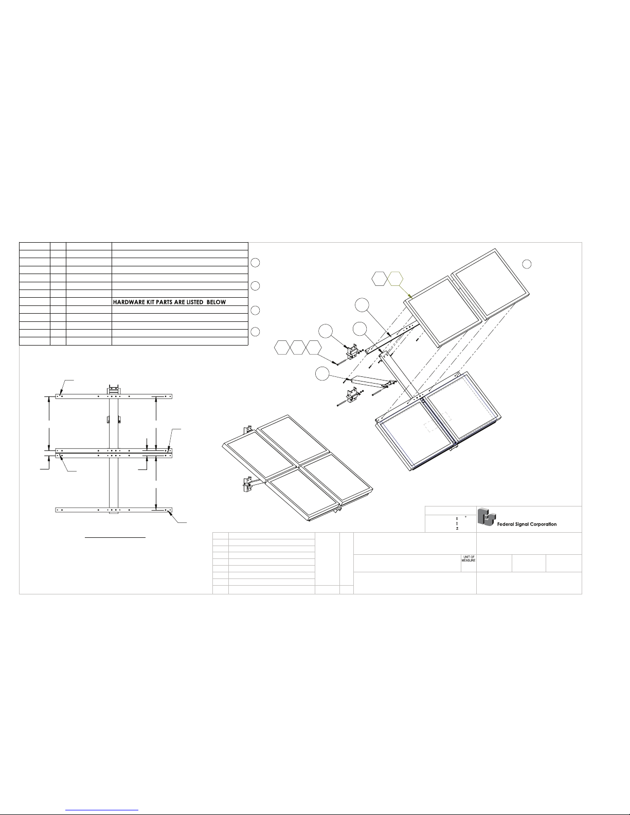
Figure 12 Final Assembly Solar Bracket 55 W or 60 W (4 Panel)
3
1
4
60W SOLAR PANEL
103102101
105104
2
ITEM NO.
QTY.
PART NO.
DESCRIPTION
1 1
2881278C
CHANNEL, BASE, SOLAR 55W (4 PANEL)
2 4
2881279B
TUBING, RECTANGULAR, SOLAR 55W/60W (2
3 1
2881284A
ASSEMBLY, WELD, SUPPORT, CHANNEL
4 2
2881286A
CHANNEL, BRACKET, WELD
5 1 2881333
HARDWARE KIT
101 3
7002080A-80
SCREW,HEX,SS,3/8-16 X 5,FULL THRD
102 3
7058A013
NUT,EL STOP,HEX,LT SS,3/8-16
103 3
7074A046
LKWSHR, SPLT, SS, 3/8
104 24
7000A311-30
SCREW, MACH, 1/4-20, HEX HD, , SS,
105 24
7058A010
NUT, EL STOP, 1/4-20, , SS,
24.75
24.75
2.19
24.69
2.25
LOCATOR
HOLE
LOCATOR
HOLE
LOCATOR
HOLE
LOCATOR
HOLE
BRACKET ASSEMBLY
D0
D0
D0
D0
D0
MATERIAL DESCRIBED AND INFORMATION CONVEYED IS
PROPRIETARY TO FEDERAL SIGNAL CORPORATION, IS OR
MAY BE THE SUBJECT OF PATENT APPLICATIONS, AND
MAY NOT BE COPIED, DIVULGED TO OTHERS, OR USED
FOR MANUFACTURING WITHOUT CONSENT.
DRAWN BY:
DATE:
CHKD. BY:
DATE:
SCALE AT B SIZE:
DRAWING NUMBER:
FINISH:
MATERIAL:
NAME:
CHANGE
DATE
BY
DIVISION
SIGNAL
2645 FEDERAL SIGNAL DRIVE - UNIVERSITY PARK,IL 60466
SC
NONE
2881287
NONE
AS SPECIFIED
FINAL ASSEMBLY, SOLAR BRACKET
55W/60W (4 PANEL)
PC
SEE ECO# 09-4542
3/10/09
VT
Tolerances Unless
Otherwise Specified
Angles -------
0.5
X.XX ----------
0.015
X.XXX ----------
0.005
REV
REMOVE BURRS, SHARP CORNERS AND EDGES
B
2/2/09
VT
1/30/09
B1
MAF
1/8/10
SEE ECR #09-5802
VT
SEE ECR# 10-7179
12/6/10
C
D0
MAF
5/23/16
SEE ECR# 5602
Page 26

26
Figure 13 Final Assembly Solar Bracket Side Mount 110 W
14
110W SOLAR PANEL
102105103
104106
3
2
ITEM NO.
QTY.
PART NO.
DESCRIPTION
1 1
861000124A
CHANNEL, BASE, SOLAR SIDE MT 110W
2 2
861000053A
TUBING, RECTANGULAR, SOLAR 110W
3 1
861000126A
ASSY., WELD, SUPPORT, CHANNEL SIDE MT 110W
4 2
2881286A
CHANNEL, BRACKET, WELD
5 1
2881333B
HARDWARE KIT
HARDWARE KIT PARTS ARE LISTED BELOW
101 12
7000A311-30
SCR,HEX HD,SS,1/4-20X1-7/8
102 3
7002080A-80
SCREW,HEX,SS,3/8-16 X 5,FULL THRD
103 3
7058A013
NUT, EL STOP, 3/8-16, 0.468/0.438" THK, SS,
104 12
7058050A
NUT,MACH SCR,KEPS,1/4-20
105 3
7074A046
LKWSHR, SPLT, SS, 3/8
106 12
7000A311-30
SCREW, MACH, 1/4-20, HEX HD, , SS,
MATERIAL DESCRIBED AND INFORMATION CONVEYED IS
PROPRIETARY TO FEDERAL SIGNAL CORPORATION, IS OR
MAY BE THE SUBJECT OF PATENT APPLICATIONS, AND
MAY NOT BE COPIED, DIVULGED TO OTHERS, OR USED
FOR MANUFACTURING WITHOUT CONSENT.
DRAWN BY:
DATE:
CHKD. BY:
DATE:
SCALE AT B SIZE:
DRAWING NUMBER:
FINISH:
MATERIAL:
NAME:
CHANGE
DATE
BY
DIVISION
SIGNAL
2645 FEDERAL SIGNAL DRIVE - UNIVERSITY PARK,IL 60466
Federal Signal Corporation
SAC
NONE
861000127A
NONE
AS SPECIFIED
FINAL ASSEMBLY, SOLAR BRACKET
SIDE MOUNT 110W
PC
SEE ECR# 841
6/24/13
VT
Tolerances Unless
Otherwise Specified
Angles -------
0.5
X.XX ----------
0.015
X.XXX ----------
0.005
REV
REMOVE BURRS, SHARP CORNERS AND EDGES
A0
6/14/13
VT
6/12/13
Page 27

27
Figure 14 Final Assembly Solar Bracket Top-of-Pole Mount 110 W (2 Panel)
5
2
3
110W SOLAR PANEL
4103108
104
1101107105
NOTE: SOLAR PANEL OMMITED FOR DETAIL
102107105
106100
7109
A1
ITEM NO.
QTY.
PART NO.
DESCRIPTION
1 1
2881295A
ASSY, WELD, CHANNEL SUPPORT, TOP-OF-PO
2 1
2881298A
WELD ASSY, BRACKET, TOP-OF-POLE MOUNT
3 1
861000052A
CHANNEL, BASE, SOLAR 110W
4 1
2881294A
ASSEMBLY, WELD, BASE BRACKET
5 2
861000053A
TUBING, RECTANGULAR, SOLAR 110W
6 1 2881335
HARDWARE KIT
7 1
8570073A
WELDMENT ASSY, PIPE SLEEVE, SOLAR, PVS22
HARDWARE KIT PARTS LISTED BELOW
100 12
7000A311-28
SCR,HEX HD,SS,1/4-20X1-7/8
101 2
7002080A-88
SCREW,HEX,SS,3/8-16 X 6-1/2
102 1
7002080A-96
SCREW,HEX,SS,3/8-16 X 6
103 1
7002A014-24
SCREW,CAP,HEX HD,SS,1/2-13 X 1-1/2
104 1
7003018A
BOLT, U, 1/2-13, , SS, FOR 4" PIPE
105 3
7058A013
NUT, EL STOP, 3/8-16, 0.468/0.438" THK, SS,
106 12
7058A010
NUT, EL STOP, 1/4-20, , SS,
107 3
7074A046
LKWSHR, SPLT, SS, 3/8
108 1
7074A059
WASHER, SPLT, 1/2, .873 OD, 0.135/0.125"
109 2
7000A338-104
SCREW HEX HD 1/2-13 SS
A2
A2
A2
MATERIAL DESCRIBED AND INFORMATION CONVEYED IS
PROPRIETARY TO FEDERAL SIGNAL CORPORATION, IS OR
MAY BE THE SUBJECT OF PATENT APPLICATIONS, AND
MAY NOT BE COPIED, DIVULGED TO OTHERS, OR USED
FOR MANUFACTURING WITHOUT CONSENT.
DRAWN BY:
DATE:
CHKD. BY:
DATE:
SCALE AT B SIZE:
DRAWING NUMBER:
FINISH:
MATERIAL:
NAME:
CHANGE
DATE
BY
DIVISION
SIGNAL
2645 FEDERAL SIGNAL DRIVE - UNIVERSITY PARK,IL 60466
Federal Signal Corporation
SAC
NONE
861000039A
NONE
AS SPECIFED
FINAL ASSEMBLY, SOLAR BRACKET
TOP-OF-POLE MOUNT 110W (2 PANEL)
REL. TO ECR # 113
10/30/12
VT
Tolerances Unless
Otherwise Specified
Angles -------
0.5
X.XX ----------
0.015
X.XXX ----------
0.005
REV
REMOVE BURRS, SHARP CORNERS AND EDGES
A0
10/30/12
VT
10/29/12
PC
SEE ECR # 768
5/21/13
VT
A1
A2
SEE ECR # 2268
8/5/14
VT
Page 28

28
Figure 15 DCB and DCFCB Solar Wiring
Page 29

29
Figure 16 DCFCTB Solar Wiring
Page 30

30
Figure 17 One-Way Solar UltraVoice Wiring Diagram
T300104-02-014
1 FUSE 2
1461309A
1461503A
20 AMP
200A
RED 4 GA
PRIMARY CABINET
SECONDARY CABINET
COM
REMOTE ACTIVATION INPUTS
SLOWBLO
RELAY
JP11
F1
JP14
600 OHM
20A
JP12
C4
CHARGER
JP20
RELAY
D2
AMP 5
COM
JP15
JP18
F5F2F1F3F4
F8F6F7
COM
SENSOR INPUTS
COM#1COM
SPR
COM
INTR
COMACSOL
PTT
600
COM
TEST
SPEAKER
JP29
JP19
JP17
JP16
DIR
-
SPR
#2
+
VISO
SOU
COM
NOR
EAS
WES
- +
24VDC
JP13
T1
C1
10A
F2
SIG-
SIG-
SIG+
SIG+
SIG-
SIG+
SIG+
SIG-
JP23
AMP 3AMP 1
JP21
AMP 2
JP22
AMP 4
JP24
SIG-
SIG+
BATTERY
(+)
JP25
SIG-
SIG+
BATTERY
(-)
AMP 6
JP26
SIG-
2005147
SIG+
JP27
AMP 7
(-)
SIG-
SIG+
AMP 8
JP28
T300422-03-059 ORN
RADIO
RS232
RX TEST
3
+
4
+
-
2
1
+
-
+
-
T300104-09-004
WHT 4 GA.
T300104-09-001
WHT 4 GA.
T300112-05-005 GRN 12 GA
T300104-10-011 BLK 4GA
T300112-02-056 RED 12 GA
T300420-05-011 GRN
T300422-03-060 ORN
BATTERY BOX CONNECTIONS
T300104-02-010
RED 4AWG
T300104-09-004
WHT 4 GA.
(1 REQUIRED
WITH 2 BATTERIES)
SW1
2
1
RED 4 GA
T300104-02-016
COMMON
OPEN
OPEN
COMMON
1461504A
C300422-09-143
WHT
2-WAY
MODELS
ONLY
122378A
2-WAY
MODELS
ONLY
122378A
NOTES:
1. BATTERY CONNECTIONS ARE MADE DURING SIREN INSTALLATION.
2. WHEN USING ONLY TWO BAT TERIES, DO NOT USE (3) WHITE 4 AWG WIRES (T300104-09-004).
3. ORANGE INTRUSION SWITCH WIRES INCLUDED FOR POSSIBLE FUTURE USE.
4. LENGTH OF WIRES IN BATTERY CABINET (MEASURED FROM CONDUIT END TO TERMINAL START ā0.5").
T300422-03-060 & T300422-03-061, ORANGE, 36"
T300104-02-016, RED, 13"
T300104-10-011, BLACK, 10.5"
1461503A, 6.5"
A7
A7
RED
BLK
BLK
RED
BLK
BLK
PV
+
+
LOAD
+
- ++- +
+
BATTERY
-
SOLAR REGULATOR
RED
+ - +
-
TO SOLAR REGULATOR PV+
BLK
BLK
-
288996 (PVS220W-24-DSA, PVS220W-24-MOD, PVS220W-24-H-S)
288995D (PVS220W-24)
-+ + ++ - - ++ - - ++ - -
RED
WHT
CONTROL CABINET
INTRUSION SWITCH
CONTROL CABINET
INTRUSION SWITCH
SEE NOTE 3
55W,12V
110W, 12V 110W, 12V
SOLAR WIRING CONFIGURATIONS
A2
WHT
A3
A4
A5
A6
55W,12V 55W,12V 55W,12V
WHT
BLK
RED
RED
+
-
WHT
BLK
+
-
+
-
+
-
288995 (PVS240W-24)
60W,12V 60W,12V 60W,12V 60W,12V
TO SOLAR REGULATOR PV-
RED
TO SOLAR REGULATOR PV+
TO SOLAR REGULATOR PV-
A1
+ - + -
+ +- -+ - + -
A REL. TO ECO# 06-4033 3/6/06 VT
N/A
AS SPECIFIED
RF
259185A
VT
3/10/06
SC
6/8/06
NONE
WIRING DIAGRAM
1-WAY, SOLAR, ULTRAVOICE
A1 SEE ECO #07-4009 1/25/07 MAF
A2 SEE ECO #07-4054 4/12/07 MAF
A3 SEE ECR #10-7179 12/6/10 VT
A4 SEE ECR #443 2/13/13 BWH
A5 SEE ECR# 2268 8/22/14 VT
A6 SEE ECR# 4142 9/8/15 MAF
A7 SEE ECR #5602 5/31/16 MAF
Otherwise Specied
------
-------
Angles
x.xx
x.xxx
-----
Tolerances Unless
±0.5°
±.015
±.005
Page 31

31
Figure 18 Two-Way Solar UltraVoice Wiring Diagram
T300104-02-014
1 FUSE 2
1461309A
1461503A
20 AMP
200A
RED 4 GA
DC CONVERTER
PRIMARY CABINET
SECONDARY CABINET
COM
REMOTE ACTIVATION INPUTS
SLOWBLO
RELAY
JP11
F1
JP14
600 OHM
20A
JP12
C4
CHARGER
JP20
RELAY
D2
AMP 5
COM
JP15
JP18
F5F2F1F3F4
F8F6F7
COM
SENSOR INPUTS
COM
#1
COM
SPR
COM
INTR
COMACSOL
PTT
600
COM
TEST
SPEAKER
JP29
JP19
JP17
JP16
DIR
-
SPR
#2
+
VISO
SOU
COM
NOR
EAS
WES
- +
24VDC
JP13
T1
C1
10A
F2
SIG-
SIG-
SIG+
SIG+
SIG-
SIG+
SIG+
SIG-
JP23
AMP 3AMP 1
JP21
AMP 2
JP22
AMP 4
JP24
SIG-
SIG+
BATTERY
(+)
JP25
SIG-
SIG+
BATTERY
(-)
AMP 6
JP26
SIG-
2005147
SIG+
JP27
AMP 7
(-)
SIG-
SIG+
AMP 8
JP28
T300422-03-059 ORN
RADIO
RS232
RX TEST
17500919
3
+
4
+
-
2
1
+
-
+
-
T300104-09-004
WHT 4 GA.
T300104-09-001
WHT 4 GA.
T300112-05-005 GRN 12 GA
T300104-10-011 BLK 4 GA
T300112-02-056 RED 12 GA
T300420-05-011 GRN
T300422-03-060 ORN
17500861
RED
BLK
BLK
RED
Federal Signal Corporation
15 AMP
148A107 (REF)
BATTERY BOX CONNECTIONS
RADIO WIRING
T300104-02-010
RED 4AWG
175902A-10
ANTENNA
EQUIPMENT
POLYPHASER
T300104-09-004
WHT 4 GA.
(1 REQUIRED
WITH 2 BATTERIES)
SW1
2
1
RED 4 GAT300104-02-016
122378A
COMMON
OPEN
OPEN
COMMON
122378A
1461504A
C300422-09-143
WHT
VX-4500
NOTES:
1. BATTERY CONNECTIONS ARE MADE DURING SIREN INSTALLATION.
2. WHEN USING ONLY TWO BAT TERIES, DO NOT USE (3) WHITE 4 AWG WIRES (T300104-09-004).
3. LENGTH OF WIRES IN BATTERY CABINET (MEASURED FROM CONDUIT END TO TERMINAL START ±0.5").
T300422-03-060 & T300422-03-061, ORANGE, 36"
T300104-02-016, RED, 13"
T300104-10-011, BLACK, 10.5"
1461503A, 6.5"
A7
BATTERY CABINET
INTRUSION SWITCH
INTRUSION SWITCH
CONTROL CABINET
AND SCREWS AROUND COILED ANTENNA CABLE.
NOTE: TAPE SACK WITH ANTENNA GASKET
+
+ -
PV++BATTERY
+ -
+
LOAD
+ -
SOLAR REGULATOR
RED
++ -- +
WHT
BLK
+ - - + +
RED
BLK
- - + + - -
288995D (PVS220W-24)
RED
BLK
RED
-
+
BLK
RED
BLK
+
-
BLK
55W,12V
110W, 12V 110W, 12V
SOLAR WIRING CONFIGURATIONS
A2
A3
WHT
A4
A5
A6
A6
A6
55W,12V 55W,12V 55W,12V
WHT
BLK
RED
RED
+
-
WHT
BLK
+
-
+
-
+
-
288995 (PVS240W-24)
60W,12V 60W,12V 60W,12V 60W,12V
288996 (PVS220W-24-DSA, PVS220W-24-MOD, PVS220W-24-H-S)
TO SOLAR REGULATOR PV+
TO SOLAR REGULATOR PV-
TO SOLAR REGULATOR PV+
TO SOLAR REGULATOR PV-
A1
+-+ -- + - +
-+ + -
A REL. TO ECO# 06-4033 3/6/06 VT
N/A
AS SPECIFIED
RF
259186A
VT
3/10/06
SC
6/8/06
NONE
WIRING DIAGRAM
2-WAY, SOLAR, ULTRAVOICE
A1 SEE ECO #07-4009 1/25/07 MAF
A2 SEE ECO #07-4054 4/12/07 MAF
A3 SEE ECR #10-7179 12/6/10 VT
A4 SEE ECR #443 2/13/13 BWH
A5 SEE ECR# 2268 8/22/14 VT
A6 SEE ECR# 4142 9/8/15 MAF
A7 SEE ECR #5602 5/31/16 MAF
Otherwise Specied
------
-------
Angles
x.xx
x.xxx
-----
Tolerances Unless
±0.5°
±.015
±.005
Page 32

32
Figure 19 Hawaii UltraVoice Wiring Diagram
1 FUSE 2
200A
SECONDARY CABINET
PRIMARY CABINET
COM
REMOTE ACTIVATION INPUTS
SLOWBLO
RELAY
JP11
F1
JP14
600 OHM
20A
JP12
C4
CHARGER
JP20
RELAY
D2
AMP 5
COM
JP15
JP18
F5
F2
F1F3F4
F8F6F7
COM
SENSOR INPUTS
COM
#1
COM
SPR
COM
INTR
COM
AC
SOL
PTT
600
COM
TEST
SPEAKER
JP29
JP19
JP17
JP16
DIR
-
SPR
#2
+
VISO
SOU
COM
NOR
EAS
WES
24VDC
JP13
T1
C1
10A
F2
SIG-
SIG-
SIG+
SIG+
SIG-
SIG+
SIG+
SIG-
JP23
AMP 3AMP 1
JP21
AMP 2
JP22
AMP 4
JP24
SIG-
SIG+
BATTERY
(+)
JP25
SIG-
SIG+
BATTERY
(-)
AMP 6
JP26
SIG-
2005147
SIG+
JP27
AMP 7
(-)
SIG-
SIG+
AMP 8
JP28
3
+
4
-
+
-
2
1
+
-
+
-
BATTERY BOX CONNECTIONS
SW1
2
1
COMMON
OPEN
OPEN
COMMON
- +
NOTES:
1. OPTIONS SHOWN IN ITALICIZED TEXT FOR REFERENCE.
2. BATTERY, SATELLITE RECEIVER & ANTENNA CONNECTIONS MADE DURING SIREN INSTALLATION.
3. WHEN USING ONLY TWO BATTERIES, DO NOT USE (3) WHITE 4 AWG WIRES (T300104-09-004).
4. LENGTH OF WIRES IN BATTERY CABINET (MEASURED FROM CONDUIT END TO TERMINAL START ±0.5").
T300420-05-011, GREEN, 36"
T300104-02-016, RED, 13"
T300104-10-011, BLACK, 10.5"
1461309A
T300104-02-014 RED 4 GA
BATTERY CABINET
INTRUSION SWITCH
INTRUSION SWITCH
CONTROL CABINET
T300422-03-059 ORN
T300104-09-004
WHT 4 GA.
T300104-09-001
WHT 4 GA.
T300112-05-005 GRN 12 GA
T300104-10-011 BLK 4 GA
T300112-02-056 RED 12 GA
T300420-05-011 GRN
T300422-03-060 ORN
T300104-02-010
RED 4AWG
T300104-09-004
WHT 4 GA.
(1 REQUIRED
WITH 2 BATTERIES)
T300104-02-016 RED 4 GA
122378A
122378A
1751620A
MODEM
1461916A
SHIELD/GND
BLU
GRN
WHT
BLK
ORG
RED
RED/BLK
CELLULAR
ANTENNA
288232A
175902A-26
Q-UV-ISAT or Q-UV-SATCELL1
2881411
1461503A
20 AMP
17500033A
C1
-
BATT
+ -
SOLAR
CONTROLLER
REMOTE
TEMP.
C300422-09-143
C300218-10-266 BLK
T300218-02-235 RED
C300218-10-266 BLK
T300218-02-235 RED
Q-UV-SATCELL1
1751186B
1751186B
1751618A
SATELLITE
RECEIVER
2881412A
RS232 1
CELL
RS232 2
SAT
71400089A-02
71400089A-01
C1
+
SOLAR
TB
1 2
+ + -
110W, 12V
- -
110W, 12V
++ -
RED
A B
24 VOLT SYSTEM: 288996 (PVS220W-24)
288455A
BUSS BAR JUMPER
BLK
RED
RED
BLK
RED
BLK BLK
3 4
RED
BLK
C3
C4
T300214-10-102 BLK
1461309A
Q-UV-SATCELL1
C4
C5
(+)
GND
+23.3V
(-)
CELLULAR SERIAL PORT
JP6
2005762
1 AMP
SATELLITE
SERIAL PORT
CELLULAR
SERIAL PORT
POWER
2 AMP
CELLULAR
POWER
I/O4
I/O2 (+)
RXD
TXD
I/O3
GND
I/O1
SATELLITE
+ - + -
TP2
R7
R4R5R2R3
D3
D2
Q3
D5
R6
TP1
F2
C2
R1
JP5
JP2
F1
D1
C1
D4
Q1
Q2
JP1
JP3
JP4
C REL. TO ECR# 12-8998 5/29/12 VT
N/A
AS SPECIFIED
RF
259298C
VT
5/25/12
RW
12/14/12
NONE
WIRING DIAGRAM, HAWAII
SOLAR IN UV
C1 SEE ECR# 12-9359 8/7/12 VT
C2 SEE ECR# 113 10/12/12 VT
C3 SEE ECR# 768 5/21/13 VT
C4 SEE ECR# 1605 2/12/14 VT
C5 SEE ECR# 2268 8/22/14 VT
Page 33

33
Figure 20 Solar Assembly for the UltraVoice
3
1
2
B2
B3B4
B4
B4
B4
B4
B4
B4
B4
# ONLY QTY 2 ON 1-WAY
## ONLY 1-WAY MODELS
### ONLY 2-WAY MODELS
B2
ITEM NO.
QTY.
PART NUMBER
DESCRIPTION
1 1
288964A-24
SOLAR REGULATOR, MORNING STAR, PROSTAR
2
4
7000A070-12
SCREW, MACH, 10-32, RND HD, PHIL, SS, 3/4
3
1
8600148A-01
BRKT ASSY, SOLAR, PROSTAR, UV
1
1461503A
1
1461504A
WIRE LEAD,SOLAR GND TO MOTHERBOARD
3
C300422-09-143
NT SHWN
1 255379
MANUAL
1 288995
1 2881287
SOLAR BRACKET
1 2881336
KIT, CABLE AND CLAMP, SOLAR
2
7000A427-10
SCREWS,6-32,SS
REF
0
259185
WIRING DIA,UV 1-WAY,SOLAR
REF
0
259186
WIRING DIA,UV 2-WAY,SOLAR
REF
0
8600109
FINAL ASSY,UV 1-WAY
REF
0
8600111
FINAL ASSY, UV 2-WAY
DELETIONS (CONT.)
QTY.
PART NUMBER
DESCRIPTION
1
1751064A-04
CABLE,AC TERMINATED
2###
C300218-09-119
WIRE,CUT,WHT,5"
2###
C300218-10-258
WIRE,CUT,BLK,5"
1###
T300422-02-094
T-WIRE,RED,28"
1###
T300422-06-060
T-WIRE,BLUE,28"
1###
T300422-10-099
T-WIRE,BLACK,28"
1
8549A193A
LIGHTNING PROTECTOR
1
1461243A
WIRE
LEAD,FUSED,POWER
SUPPLY
1
81461875B
LABEL,NAMEPLATE,UL
1
1612875A-05
LABEL, ELECTRICAL
RATINGS
DELETIONS FOR SOLAR OPTION (1-WAY & 2-WAY)
QTY.
PART
NUMBER
DESCRIPTION
1 120816
CHARGER,24V,10A
1
1612393B
LABEL,DIN RAIL,UV
2
229218A
BRKT,T-BLOCK,END
4#
229282A
TERM. BLOCK,1-POLE,35MM
DIN
1##
229283A
CAP,END,TERM BLOCK,1
POLE
1
229288A
GROUND TERM BLOCK,3
POS
1
288810A-04
DIN
RAIL,ALUM,UNCOATED,4.00"
1###
288454B
INPUT MODULE,120V
2
7011A152-06
#8 SHT METAL SCREW,SS
6
7058050A
NUT,MACH SCREW,KEPS 1/420
1
8600112A-01
BRKT ASSY,PWR SUPPLY
MATERIAL DESCRIBED AND INFORMATION CONVEYED IS
PROPRIETARY TO FEDERAL SIGNAL CORPORATION, IS OR
MAYNOT BE COPIED, DIVULGED TO OTHERS, OR USED
FOR MANUFACTURING WITHOUT CONSENT.
CHANGE
DATE
BY
DIVISION
SIGNAL
2645 FEDERAL SIGNAL DRIVE - UNIVERSITY PARK,IL 60466
Federal Signal Corporation
NONE
8600124B
N/A
N/A
SOLAR ASSY,UV
RF
REL TO PROD ECO #05-4142
9/21/05
MAF
0.5
0.015
0.005
REV
REMOVE BURRS, SHARP CORNERS AND EDGES
B1
9/21/05
MAF
7/8/05
B3
SEE ECO #08-2746
2/26/08
VT
MAF
11/22/05
SEE ECO #05-4180
B2
B4
MAF
5/31/16
SEE ECO #5602
Page 34

34
Figure 21 Solar Assembly for the DC Series Siren Control System
UNITS: INCHES
D
A
A
1
B
C
B
2
1
C
D
2
SHEET: 1 OF 1
THIRD ANGLE
PROJECTION
DATE:
DATE:
REMOVE BURRS, SHARP CORNERS AND EDGES
UNIT OF
MEASURE
DRAWN BY:
CHKD. BY:
DRAWING NUMBER
SCALE AT B SIZE:
MATERIAL
FINISH
NAME
S
AFETY &
S
ECURITY
G
ROUP
FEDERAL SIGNAL
2645 FEDERAL SIGNAL DRIVE
UNIVERSITY PARK, IL 60484
ā
0.5
Ā
ā
0.015[ā0.4]
ā
0.005[ā0.12]
------
-----
---
IN[mm]
Angles
x.xx[x.x]
x.xxx[x.xx]
Tolerances Unless Otherwise Specified
BYDATE
CHANGE
REV.
MATERIAL DESCRIBED AND INFORMATION CONVEYED IS PROPRIETARY TO FEDERAL SIGNAL CORPORATION, IS OR
MAY BE THE SUBJECT OF PATENT APPLICATIONS, AND MAY NOT BE COPIED, DIVULGED TO OTHERS, OR USED
FOR MANUFACTURING WITHOUT CONSENT.
7/8/05
MAF
9/21/05
MJF
EA
SOLAR ASSY, DC, 48V
N/A
N/A
8402166C
NONE
ITEM #
QTY. PART NO. DESCRIPTION
1 1 2881240A TS DIGITAL METER
2 1 288812A SOLAR REGULATOR, TS-45
3 4 7000A070-12
SCREW, MACH, 10-32, RND HD, PHIL, SS, 3/4
4 1 7058050A
NUT,MACH SCR,KEPS,1/4-20
* 1 C300214-02-132 CUT WIRE,RED,35"
* 1 C300214-10-092 CUT WIRE,BLACK,35"
** 1 288995 SOLAR KIT,SUNWIZE
REF 0 259187
WIRING DIA,DCB/DCFCB, SOLAR
REF 0 259188 WIRING DIA,DCFCTB, SOLAR
REF 0 8402147 FINAL ASSY,DCFCTB
REF 0 8402148 FINAL ASSY,DCFCB
NOT SHOWN 1 17500033A REMOTE SENSOR
NOT SHOWN 1 255379 MANUAL
NOT SHOWN 1 2881287
SOLAR BRKT ASSY, 55W/60W (4 PANEL)
NOT SHOWN 1 2881336A KIT, CABLE AND CLAMP, SOLAR
5 1 840200308A BRKT ASSY, SOLAR REG MOUNT
* SHOWN ON
WIRING DIAGRAM
** NOT SHOWN, SHIPPED
DIRECT TO CUSTOMER
C1
C2
9/21/05
SEE ECR #6821
12/28/16
MAFC0
VTB2
112/3/07
SEE ECO #07-4186
MAF
11/22/05
SEE ECO #05-4180
B1
B
MAF
REL TO PROD. ECO #05-4143
AEO
5/17/2017
REL FOR ECR #7436
C1
C2
REL FOR ECR #8128
8/8/2017
AEO
DELETIONS FOR SOLAR OPTION (1-WAY & 2-WAY)
QTY PART NO. DESCRIPTION
2 143139A FUSE LEVER
2 143140A FUSE COVER
1 1461361A WIRE LEAD,110V PWR
2 148154A FUSE,10A
1 1461389A WIRE ASSY,BAT CHRGR
1 1612400A LABEL, FC CONTROL
1 1612875A-03 LABEL, UL ELECT. RATING
1 1751064A-04 CABLE,AC FOR BATT CAB.
2 229218A BRKT,BLOCK END
4 229282A TERM BLOCK
1 229288A GROUND TERM BLOCK
2 288782A JUMPER
1 288810A-04 DIN RAIL
2 7011A069-08 SCREW
4 7058050A
KEPS NUT,1/4-20
1 81461875B LABEL, NAMEPLATE
1 840200205 BATTERY CHARGER
1 8549A193A LIGHTNING PROTECT.
1 C300218-09-119 CUT WIRE
1 C300218-10-258 CUT WIRE
C1
3
5
4
1
2
 Loading...