

Federal Signal Corporation Personnel Alerting System Installation And Operation Instructions Manual
Page 1

Federal Signal UltraVoicetm
Personnel Alerting System
Including Models:
UltraVoice Indoor Controller (UVIC)
UltraVoice Audio and Relay Module (UVARM)
UltraVoice Local Operation Console (UVLOC)
INSTALLATION and OPERATION
255364F
4/07 Copyright 2007 Federal Signal Corporation
INSTRUCTIONS
Page 2

Federal Signal UltraVoice
Installation and Operation Manual
SAFETY NOTICES
People’s lives depend on your selection of suitable equipment and installation sites and
your safe installation, service, and operation of our products. Federal Signal recommends the
following publications from the Federal Emergency Management Agency for assistance with
planning an outdoor warning system: 1. The “Outdoor Warning Guide (CPG 1-17), 2. “Civil
Preparedness, Principles of Warning” (CPG 1-14), 3. FEMA-REP-1, Appendix 3 (Nuclear Plant
Guideline), and 4. FEMA-REP-10 (Nuclear Plant Guideline). Contact Federal Warning System’s
Customer Care Center at:
further information about these publications.
It is important to read, understand and follow all instructions shipped with this product. In
addition, listed below are some other important safety instructions and precautions you should
follow.
• If suitable warning equipment is not selected, the installation site for the siren is not selected
properly or the siren is not installed properly, it may not produce the intended optimum
audible warning. Follow Federal Emergency Management Agency (FEMA)
recommendations.
• If sirens or speakers are not activated in a timely manner when an emergency condition
exists, they cannot provide the intended audible warning. It is imperative that
knowledgeable people, who are provided with the necessary information, are available at all
times to authorize the activation of the sirens or speakers.
• When sirens are used out of doors, people indoors may not be able to hear the warning
signals. Separate warning devices or procedures may be needed to effectively warn people
indoors.
• The sound output of sirens is capable of causing permanent hearing damage. To prevent
excessive exposure, carefully plan siren placement, post warnings, and restrict access to
areas near sirens.
• Activating the sirens or speakers may not result in people taking the desired actions if those
to be warned are not properly trained about the meaning of warning sounds. Siren users
should follow FEMA recommendations and instruct those to be warned of correct actions to
be taken.
• A siren or speaker that doesn’t work won’t provide any warning. After installation, service, or
maintenance, test the mass notification system to confirm that it is operating properly. Test
the system regularly to confirm that it will be operational in an emergency.
http://www.federalwarningsystems.com or 1-800-524-3021 for
PLANNING
SAFETY NOTICES
2
Page 3

Federal Signal UltraVoice
Installation and Operation Manual
• If future service and operating personnel do not have these instructions to refer to, the siren
system may not provide the intended audible warning and service personnel may be
exposed to death, permanent hearing loss, or other bodily injury. File these instructions in a
safe place and refer to them periodically. Give a copy of these instructions to new recruits
and trainees. Also give a copy to anyone who is going to service or repair the siren.
People’s lives depend on your safe installation, service and operation of our products. It is
important to read, understand and follow all instructions shipped with this product. In addition,
listed below are some other important safety instructions and precautions you should follow:
INSTALLATION & SERVICE
• Electrocution or severe personal injury can occur when performing various installation and
service functions such as making electrical connections, drilling holes, or lifting equipment.
Therefore experienced electricians in accordance with national, state and any other
electrical codes having jurisdiction should perform installation. All work should be performed
under the direction of the installation or service crew safety foreman.
• The sound output of sirens or speakers is capable of causing permanent hearing damage.
To prevent excessive exposure, carefully plan siren placement, post warnings and restrict
access to areas near the sirens. Sirens and distributed speakers may be operated from
remote control points. Whenever possible, disconnect all siren power including batteries
before working near the siren.
• After installation or service, test the siren system to confirm that it is operating properly.
Test the system regularly to confirm that it will be operational in an emergency.
• If future service personnel do not have these warnings and all other instructions shipped
with the equipment to refer to, the siren or distributed speaker system may not provide the
intended audible warning and service personnel may be exposed to death, permanent
hearing loss, or other bodily injury. File these instructions in a safe place and refer to them
periodically. Give a copy of these instructions to new recruits and trainees. Also, give a
copy to anyone who is going to service or repair the sirens. For additional copies, call the
Federal Warning Systems Customer Care Center at 800-524-3021 or write to them at 2645
Federal Signal Drive, University Park, IL 60466.
OPERATION
• Failure to understand the capabilities and limitations of your siren system could result in
permanent hearing loss, other serious injuries or death to persons too close to the sirens
when you activate them or to those you need to warn. Carefully read and thoroughly
understand all safety notices in this manual and all operations-related-items in all instruction
manuals shipped with equipment. Thoroughly discuss all contingency plans with those
responsible for warning people in your community, company, or jurisdiction.
SAFETY NOTICES
3
Page 4

Federal Signal UltraVoice
Installation and Operation Manual
WARNING
Read and understand the information contained
in this manual, before attempting to install or
service this product.
Pay careful attention to the following notices located on the equipment.
A. NOTICES - EXTERNALLY PLACED
B. NOTICES-INTERNALLY PLACED
SAFETY NOTICES
4
Page 5

Federal Signal UltraVoice
Installation and Operation Manual
Limited Warranty
The Federal Warning Systems Division of Federal Signal Corporation warrants each new product to
be free from defects in material and workmanship, under normal use and service, for a period of two
years on parts replacement and factory-performed labor (one year for Informer, EAS, and Federal
software products) from the date of delivery to the first user-purchaser. Federal Warning Systems
warrants every 2001 & Eclipse Siren (Top of pole only) to be free from defects in material, per our
standard warranty, under normal use and service for a period of five years on parts replacement.
During this warranty period, the obligation of Federal is limited to repairing or replacing, as Federal
may elect, any part or parts of such product which after examination by Federal discloses to be
defective in material and/or workmanship.
Federal will provide warranty for any unit which is delivered, transported prepaid, to the Federal factory
or designated authorized warranty service center for examination and such examination reveals a
defect in material and/or workmanship.
This warranty does not cover travel expenses, the cost of specialized equipment for gaining access to
the product, or labor changes for removal and re-installation of the product. The Federal Signal
Corporation warranty shall not apply to components or accessories that have a separate warranty by
the original manufacturer, such as, but not limited to, batteries.
Federal will provide on-site warranty service during the first 60-days after the completion of the
installation, when Federal has provided a turn-key installation including optimization and/or
commissioning services.
This warranty does not extend to any unit which has been subjected to abuse, misuse, improper
installation or which has been inadequately maintained, nor to units which have problems related to
service or modification at any facility other than Federal factory or authorized warranty service centers.
Moreover, Federal shall have no liability with respect to defects arising in Products through any cause
other than ordinary use (such as, for example, accident, fire, lightning, water damage, or other
remaining acts of god).
THERE ARE NO OTHER WARRANTIES, EXPRESSED OR IMPLIED, INCLUDING BUT NOT
LIMITED TO, ANY IMPLIED WARRANTIES OF MERCHANTABILITY OR FITNESS FOR A
PARTICULAR PURPOSE. IN NO EVENT SHALL FEDERAL BE LIABLE FOR ANY LOSS OF
PROFITS OR ANY INDIRECT OR CONSEQUENTIAL DAMAGES ARISING OUT OF ANY SUCH
DEFECT IN MATERIAL WORKMANSHIP.
2645 Federal Signal Drive, University Park, IL 60466
Phone: (800) 524-3021 Fax: (708) 534-4865
Website: http://www.federalwarningsystems.com
TABLE OF CONTENTS
5
Page 6

Federal Signal UltraVoice
Installation and Operation Manual
TABLE OF CONTENTS
Section Page
SAFETY NOTICES.................................................................................................................. 2
1.1 General Description................................................................................................. 10
1.2 Model Number Descriptions.................................................................................... 11
1.3 Standard Feature Descriptions:............................................................................... 11
1.4 Motherboard Description......................................................................................... 17
1.5 Configuration...........................................................................................................17
Unit Type........................................................................................................................18
Unit Address................................................................................................................... 18
RF Frequency................................................................................................................. 19
Single-Tone, Two-Tone Timing...................................................................................... 19
EAS Location Codes ......................................................................................................19
128-bit Encryption Key ...................................................................................................19
Security Key................................................................................................................... 20
User Programs............................................................................................................... 20
Available Functions: .......................................................................................................21
2. SPECIFICATIONS ......................................................................................................... 22
2.1 Electrical.................................................................................................................. 22
2.2 Charger................................................................................................................... 22
2.3 Battery..................................................................................................................... 23
2.4 Controller................................................................................................................. 23
Serial & I2C Ports........................................................................................................... 23
Signaling Formats .......................................................................................................... 23
Audio Output to Amplifiers .............................................................................................. 24
2.5 Motherboard............................................................................................................ 24
Relay Output .................................................................................................................. 24
600 Ohm Balanced Line Port ......................................................................................... 24
Remote Activation, Sensor and Direction Inputs............................................................ 24
Expansion Slot ............................................................................................................... 25
Amplifier Outputs............................................................................................................ 25
Motherboard Connectors ................................................................................................ 25
Indicators........................................................................................................................ 28
Fuses ............................................................................................................................. 28
2.6 UVIC25SD............................................................................................................... 28
2.7 Controller Front Panel Controls, Jacks, Switches and Indicators............................ 30
Controls:......................................................................................................................... 30
Jacks:............................................................................................................................. 30
Indicators:....................................................................................................................... 31
Control Unit Connector Configuration............................................................................. 32
2.8 Audio Power Amplifier Modules Model (UV400) ..................................................... 34
2.9 Audio and Relay Output Card Option (2005300)..................................................... 35
Connectors..................................................................................................................... 35
TABLE OF CONTENTS
6
Page 7

Federal Signal UltraVoice
Installation and Operation Manual
Indicators........................................................................................................................ 36
2.10 Model UVLOC......................................................................................................... 37
UVLOC Connectors........................................................................................................ 37
2.11 Alarm Panel Interface.............................................................................................. 37
Alarm Panel Interface Connectors.................................................................................. 38
2.12 Environmental ......................................................................................................... 39
2.13 Physical................................................................................................................... 39
3. UVIC OPERATION......................................................................................................... 40
3.1 Hardware General Description................................................................................ 40
3.2 Manual Activation.................................................................................................... 40
3.3 Local Public Address............................................................................................... 41
3.4 Relay Output........................................................................................................... 41
3.5 600 Ohm I/O............................................................................................................ 41
3.6 Remote-Landline Activation .................................................................................... 41
3.7 Sensor Inputs and Isolated Sensor Power.............................................................. 42
3.8 Spare Sensor Inputs................................................................................................ 43
3.9 Two-Way Status Monitoring.................................................................................... 43
3.10 Quiet Test................................................................................................................ 43
B. Finding Faults.......................................................................................................... 43
3.11 Battery Charger....................................................................................................... 44
3.12 UVLOC.................................................................................................................... 45
4. SYSTEM PLANNING ..................................................................................................... 46
4.1 Control Unit.............................................................................................................46
4.2 Speaker Placement................................................................................................. 46
4.3 UVLOC Placement.................................................................................................. 47
5. INSTALLATION.............................................................................................................. 48
5.1 UVIC Siren Controller Installation Reference Drawings .......................................... 48
5.2 General Mounting Guidelines For All Applications ..................................................52
5.3 UVIC Installation Material List and Installation Guidelines ...................................... 53
Concrete or Filled Cement Block Wall Mounting Guidelines: ......................................... 53
Hollow Block Wall Mounting Guidelines: ........................................................................ 53
Wood Stud Wall Mounting Guidelines:........................................................................... 54
Metal Stud Wall Mounting Guidelines:............................................................................ 55
5.4 Installer Supplied UVIC Electrical Installation Material List ..................................... 56
5.5 Electrical Connections............................................................................................. 57
Grounding Requirements ...............................................................................................57
AC Power Connections ..................................................................................................57
Wiring Guidelines for 120VAC Electrical Service ........................................................... 57
Wiring Guidelines for 240VAC Electrical Service ........................................................... 58
Battery Connections....................................................................................................... 58
5.6 Antenna Types........................................................................................................ 59
5.7 Cabinet Mounted Magnetic Base Antenna Installation............................................ 59
5.8 Remote Mounted Magnetic Base Antenna Installation............................................ 59
5.9 Yagi Antenna Installation......................................................................................... 59
TABLE OF CONTENTS
7
Page 8

Federal Signal UltraVoice
Installation and Operation Manual
Final VSWR Tuning........................................................................................................ 60
Yagi Antenna Mounting.................................................................................................. 61
5.10 Omni Antenna Installation .......................................................................................61
5.11 Speaker Connections.............................................................................................. 65
5.12 PA Audio Connections ............................................................................................ 65
5.13 Contact Closure Inputs............................................................................................ 65
5.14 Optional UVARM Connections................................................................................ 65
5.15 Optional UVLOC Connections and Wall Mounting.................................................. 66
5.16 External 24VDC Power Connections....................................................................... 66
5.17 600 Ohm I/O Connections....................................................................................... 66
Control Connections....................................................................................................... 66
Audio Connections.........................................................................................................66
5.18 Turning Power On...................................................................................................67
6. PRE-OPERATION CHECKOUT AND TEST.................................................................. 71
6.1 Visual Inspection..................................................................................................... 71
6.2 Amplifier and Speaker Pre-Operation Checkout ..................................................... 71
6.3 Radio Transceiver Adjustment Procedure............................................................... 72
6.4 600 Ohm Level Adjustment Procedure for Communications................................... 72
6.5 600 Ohm Adjustment Procedure for External Audio Source ................................... 73
6.6 Control and Status Monitoring................................................................................. 73
6.7 Optional UVLOC ..................................................................................................... 73
7. MAINTENANCE............................................................................................................. 76
7.1 Control Unit Preventive Maintenance...................................................................... 77
7.2 General Maintenance.............................................................................................. 77
Signal Operational Check............................................................................................... 77
Battery Check................................................................................................................. 77
7.3 Troubleshooting ...................................................................................................... 78
8. OPTIONS....................................................................................................................... 79
8.1 Radio Control.......................................................................................................... 79
8.2 Digital Voice Recording...........................................................................................79
8.3 UVIC25ST Option.................................................................................................... 79
8.4 UVIC25SD Option................................................................................................... 79
8.5 UVARM Option........................................................................................................ 79
8.6 UVLOC Option.......................................................................................................80
8.7 Installation of User Supplied Radio Receivers ........................................................ 80
9. Final Assembly Drawing and Parts List.......................................................................... 82
TABLE OF CONTENTS
8
Page 9

Federal Signal UltraVoice
Installation and Operation Manual
TABLE OF FIGURES
Figure 1.1 - UVIC Parts Layout.............................................................................................. 13
Figure 1.2 – Control and Amplifier Identification.................................................................... 14
Figure 1.3 – UVARM Identification ........................................................................................ 15
Figure 1.4 – UVLOC Identification......................................................................................... 16
Figure 2.1 - Motherboard Outline Drawing ............................................................................ 29
Figure 5.1 - Typical UVIC Installation Drawing...................................................................... 48
Figure 5.2 - UVIC Cabinet Dimensional Outline Drawing ......................................................49
Figure 5.3 – UVIC Wiring Diagram........................................................................................ 50
Figure 5.4 – UVIC Battery Connections................................................................................. 51
Figure 5.5 - Yagi Antenna Installation Example..................................................................... 62
Figure 5.6 - Omni Antenna Installation Example ...................................................................63
Figure 5.7 – Antenna Grounding Example ............................................................................ 64
Figure 5.8 – UVIC Strobe and Speaker Wiring...................................................................... 67
Figure 5.9 - UVLOC Interface Wiring Diagram ......................................................................68
Figure 5.10 - UVLOC Dimensional Outline............................................................................ 69
Figure 5.11 – UVIC25SD Wiring Diagram .............................................................................70
Field Test Data Sheet............................................................................................................ 75
Figure 9.1 – UVIC Final Assembly and Parts List (Page 1 of 2)............................................ 82
Figure 9.2 – UVIC25ST Wiring Detail.................................................................................... 84
TABLE OF CONTENTS
9
Page 10

Federal Signal UltraVoice
Installation and Operation Manual
SECTION I
1.1 General Description
The UltraVoice Indoor Controller (UVIC) is designed to fulfill the need for an indoor
electronic controller that is smaller and less expensive than the full size UltraVoice
outdoor warning siren controller. It shares the same control board and amplifiers as the
standard UltraVoice but is limited to 800 total Watts of amplifier power, and uses a
single, wall-mountable NEMA1 / UL Type 1 rated enclosure that has a built-in lock.
The use of smaller, sealed VRLA AGM type batteries minimizes battery out-gassing and
makes the controller better suited for indoor operation.
Model UVARM: The UVIC supports an optional Audio and Relay Output Module (model
UVARM) that provides three audio outputs and four relay outputs to enable the UVIC to
be connected to existing PA systems or other auxiliary devices.
Model UVLOC: An optional Local Operation Console (model UVLOC) enables users to
control the UVIC from an easy to use pushbutton control panel. The panel is connected
to the UVIC with a standard CAT5 network cable and may be located up to ½ mile away
from the UVIC controller. The UVLOC is remotely powered from the UVIC and requires
no local power source of it’s own. The panel measures only 10” x 4.75” x 3” (L x W x D)
and is easily wall mounted. The UVLOC provides control for 7 digital recordings: Live
P.A., P.A. Recording from an integrated microphone, Recorded P.A. Playback, and two
Auxiliary user programmable functions.
Model UVIC25ST: An optional 25 volt step-down transformer may be required to
convert 70 volts to 25 volts, depending on location and installation.
Model UVIC25SD:
convert 70 volts to 25 volts, depending on location and installation. The UVIC25SD
includes two step-down transformers in a NEMA 4X fiberglass enclosure.
Model UVIC: The amplifiers and optional equipment are all modularly constructed to
ease removal without disconnecting a large number of wires. In most instances, field
service is limited to replacement of a slide out module, which can be performed by nontechnical personal with only a screwdriver.
Activation codes, command sequences, and operating parameters are uploaded from
an IBM compatible computer through the RS232 port located on the front panel or over
the radio channel with the Federal Commander Digital System. All user information is
stored in non-volatile FLASH memory, immune to power and battery failure.
Refer to Figures 1.1, 1.2, 1.3 and 1.4 for reference.
An optional 25 volt step-down transformer may be required to
GENERAL DESCRIPTION
10
Page 11

Federal Signal UltraVoice
Installation and Operation Manual
1.2 Model Number Descriptions
All UVIC models are set up for 2-way control and status monitoring using the Federal
Commander Digital Control system including a 13.6V radio power supply and antenna
lightning protector. All models include 8 minutes of digital voice storage. Custom digital
voice recording requires a model DVR. All of the following models are available in a
240VAC version by adding a 240 to the model number i.e.: UVICH240.
CONTROLLER OPTIONS UVIC MODEL #
NO RADIO (RF) UVIC
UHF BAND Transceiver UVICU
HIGH BAND Transceiver UVICH
LOW BAND Transceiver UVICL (Special Order)
1.3 Standard Feature Descriptions:
• Seven standard warning signals
• Up to 16 digitally stored voice messages; 8 minutes total recording time
• Local push-button control
• Local microphone for PA with hanger mounted in cabinet
• 8 remote contact closure inputs for activation
• Single tone, 2-tone, DTMF, EAS and MSK decoders for remote siren control
• MSK modem with 128-bit encryption for remote status monitoring over radio or
wire
• 600 ohm I/O for wire-line control and status monitoring
• 15A relay output
• Quiet test - siren status monitoring
• Zoning - up to 8 zones per control cabinet for selective control of speaker outputs
• Power control ramps up siren or speaker volume for added safety, custom volume
settings, and low power testing
• Stackable siren or distributed speaker functions enable user pre-defined warning
scenarios
• Low band, VHF, or UHF radio transceiver options
• Modular design - no inter-board wiring, easy field service
• Windows
®
based siren programming software (optional)
• Cabinet:
- Single NEMA1/UL type 1, powder coated steel cabinet
- Single lockable door hasp that can be easily opened without tools
- Wall mountable
- 8 multi-size knockouts for conduit entrances
- Bulkhead mounted type N female antenna connection
GENERAL DESCRIPTION
11
Page 12

Federal Signal UltraVoice
Installation and Operation Manual
• Amplifiers (Model UV400):
- 2 amplifier slots for 400 Watt amplifiers, 70Vrms
- Optionally, one UV400 with a UVIC25ST (25Vrms step-down transformer)
- 12 speaker pair connections per amplifier
• Audio and Relay Output Module (UVARM) Option:
- Balanced 33 ohm output
- Balanced 600 ohm output
- Selectable balanced or single-ended 600 ohm line-level output
- Four SPDT relay outputs
• Local Operation Console (UVLOC and UVLOC-IM) Option:
- Operator interface panel for controlling 7 digital messages, Live P.A., Record
and Playback functions, plus two user programmable functions.
- Remotely powered from the UVIC controller
- LED status indicators
- Balanced 600 ohm output
- CAT5 wiring interface
• Batteries:
- 44 A/H (min), sealed VRLA AGM type
- Over 45 minutes full sounding battery backup without AC power
• Battery Charger:
- 24 VDC, 10A
- Temperature compensated
GENERAL DESCRIPTION
12
Page 13

Federal Signal UltraVoice
Installation and Operation Manual
MOUNTING HOLES
UV400 AMPLIFIERS
UVARM I/0 MODULE
(OPTIONAL)
(TOP & BOTTOM FLANGES)
CONTROL MODULE
INTRUSION SWITCH
BATTERY CHARGER
230/115VAC STEPDOWN
TRANSFORMER
(240 MODELS ONLY)
AC POWER
FIELD WIRING
TYPE N-FEMALE
ANTENNA CONNECTOR
TRANSCEIVER
DC POWER
CONNECTIONS,
FUSING & SPEAKER
FIELD WIRING.
(BEHIND COVER PLATE)
(2) 12VDC
BATTERIES
CONDUIT KNOCKOUTS
Figure 1.1 - UVIC Parts Layout
GENERAL DESCRIPTION
13
291327A
NOTE: CABINET DOOR
NOT SHOWN
Page 14
Federal Signal UltraVoice
Installation and Operation Manual
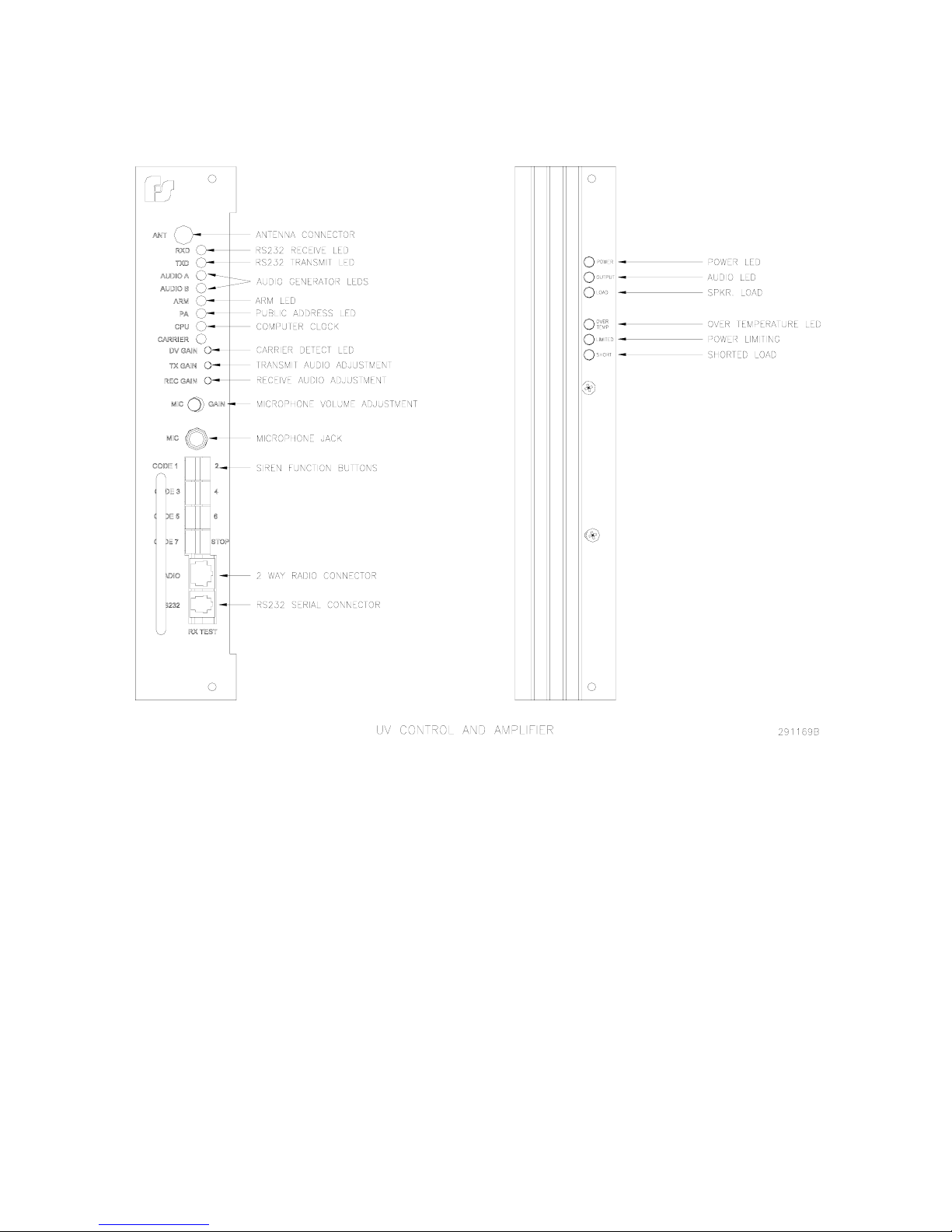
Control Amplifier
Figure 1.2 – Control and Amplifier Identification
GENERAL DESCRIPTION
14
Page 15

Federal Signal UltraVoice
Installation and Operation Manual
1.
Figure 1.3 – UVARM Identification
GENERAL DESCRIPTION
15
Page 16
Federal Signal UltraVoice
Installation and Operation Manual
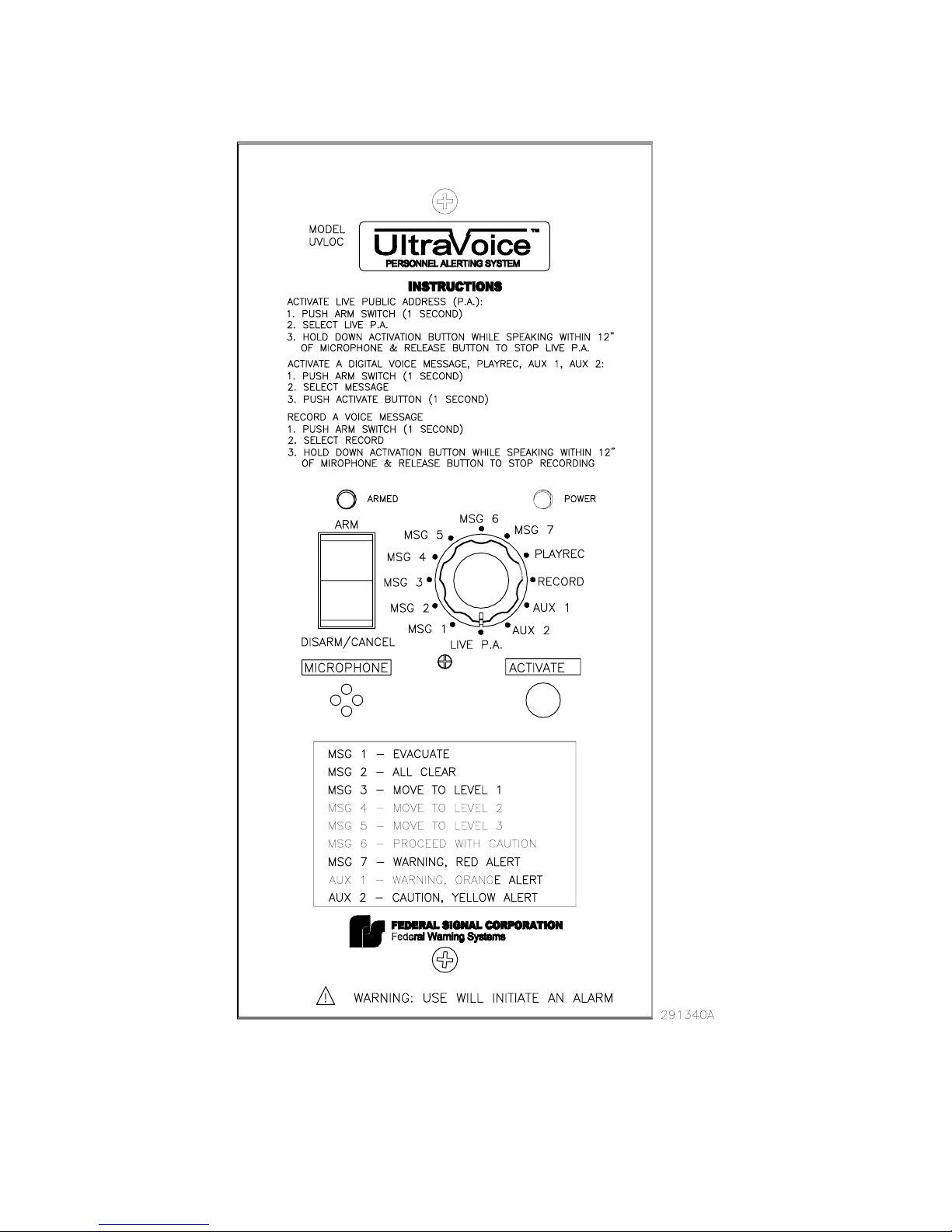
Figure 1.4 – UVLOC Identification
GENERAL DESCRIPTION
16
Page 17

Federal Signal UltraVoice
Installation and Operation Manual
1.4 Motherboard Description
The Motherboard for the UVIC is a scaled down 800 Watt version of the 3200 Watt
UltraVoice product. The board is primarily a passive back plane that provides the
electrical connections between the Microprocessor Control board, the Audio and Relay
output board, and the UV400 amplifiers. In addition, it provides connections for field
wiring and a relay output.
The UVIC Motherboard is limited to two amplifier slots. It uses the same style
connectors as the UltraVoice except for the removable fused 50A, 24VDC power input
and the 50A, 24VDC output connector.
The Motherboard has a fused normally open relay output. The relay is normally
programmed to close while a control function is active. An LED indicator turns on when
the relay is active.
Capacitor C1 and inductor T1 are used to filter the 24VDC power source. This filtered
power is fused by F2 and is routed to JP1, JP2, JP6 and JP7.
1.5 Configuration
Each modular UltraVoice siren contains the following configuration parameters, which
are configured by the user:
1. Unit Type
2. Unit Address (see below)
3. RF Frequency
4. Single-Tone or Two-Tone Timing (A-time, B-time, S-time)
5. EAS Location Codes
6. 128-bit Encryption Key
7. Security Key
GENERAL DESCRIPTION
17
Page 18
Federal Signal UltraVoice
Installation and Operation Manual
Unit Type
The Unit Type is set to the type of siren this unit is controlling, and is usually determined
by the number of cells in the speaker array. When setting up the unit type, the user
selects from a menu with the following choices:
UV1 1 - UV400 Amplifier, 400 Watts total power
UV2 2 - UV400 Amplifiers, 800 Watts total power
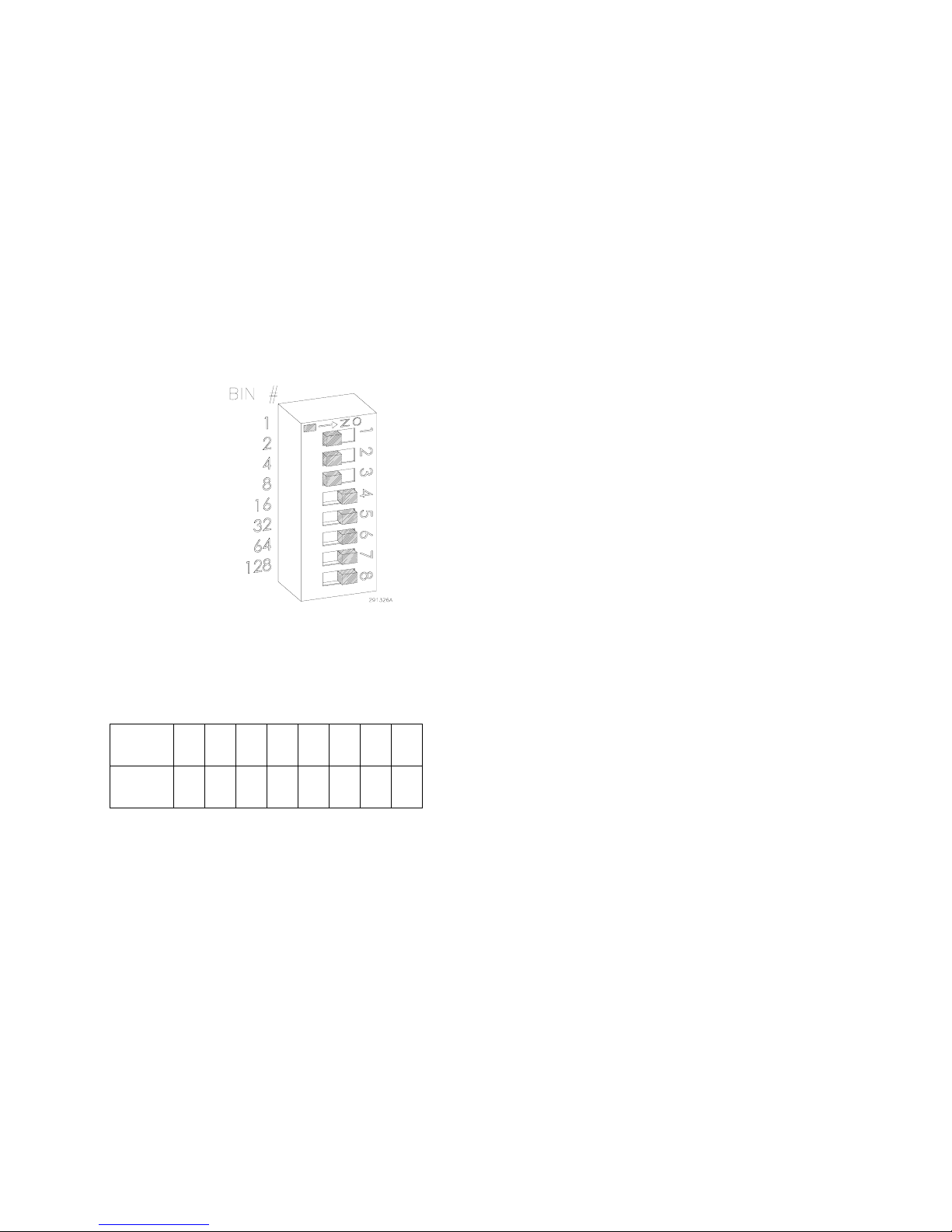
Unit Address
Address Switch
The Unit Address is a three-digit number with a range of 001-255. The unit address is
set via dipswitch S1. S1 Off position indicates active position. Add binary active switch
positions to get ID address.
Switch
number 1 2 3 4 5 6 7 8
Binary
number
1 2 4 8 16 32 64 128
Example: Switch number 1, 2 & 3 is binary number 1, 2 & 4, which when added, would
equal unit address 7.
Programming details are in the software manual. The ID address is stored at power up
of the controller. If the ID address is changed, the power (battery and AC) must be
turned off and then on.
GENERAL DESCRIPTION
18
Page 19

Federal Signal UltraVoice
Installation and Operation Manual
RF Frequency
For units equipped with the optional integral radio receiver, the RF Frequency
configuration parameter sets the frequency of the radio channel. Changing this
parameter from its factory setting may require re-alignment of the radio for maximum
performance. The value entered must fall within the range specified for the receiver
band equipped.
Single-Tone, Two-Tone Timing
For Two-Tone activated units, the Two-Tone Timing parameters set up the time
duration of the activation tone codes. The three parameters, A-Time, B-Time, and STime; sets the time duration for the A-tone, B-tone, and Single-Tone respectively. Note:
The Two-Tone timing parameters are minimum values only. The actual tone times may
be longer than the specified times.
EAS Location Codes
Up to three location codes may be assigned for EAS activation. For activation to occur,
the location code of the received EAS message must match one of the three assigned
codes.
Units cannot be programmed for both Tone and EAS activation at the same time.
Therefore, when using EAS decoding, the A-Time, B-Time, and S-Time parameters
above must be set to zero. The UVIC is capable of being programmed for EAS, DTMF
and Federal Digital decoding at the same time. Refer to www.fcc.gov for further
information about EAS messages.
128-bit Encryption Key
For MSK activated units, 128-bit data encryption provides security against malicious
operation or monitoring. The 128-bit key is programmed during the flashing of the
microprocessor and must match the encoder (SS2000D or SFCDWARE) being used to
activate the unit. A key value of zero disables 128-bit encryption and must be used if the
encoder does not support 128-bit encryption. All sites in the system must use the same
encryption key.
GENERAL DESCRIPTION
19
Page 20

Federal Signal UltraVoice
Installation and Operation Manual
Security Key
For MSK activated units, the Security Key is a unique number assigned to the system
that prevents nearby systems operating on the same RF frequency from interfering. Like
the 128-bit encryption key, the Security Key is programmed during the flashing of the
microprocessor and must match the encoder. The exception is a key value of 65535
(the default), defined as an “open” system and will communicate with all encoders
regardless of the encoder’s key setting.
User Programs
The UVIC has the capacity to store up to fifty (50) user programs. Each user program
contains the following elements:
1) Optional DTMF Activation Code
2) Optional Two-Tone Activation Code
3) Optional EAS Event Code
4) List of up to 20 functions
The ability to assign more than one function to each activation code or user program is
a new feature not previously found in electronic sirens. This allows the user to run a
sequence of functions without sending additional activation commands, greatly
enhancing flexibility while reducing operator involvement and communication channel
traffic.
GENERAL DESCRIPTION
20
Page 21

Federal Signal UltraVoice
Installation and Operation Manual
Available Functions:
Arm
Disarm
Report
Master Reset
Cancel
PA Output
Quiet Test
Low Power Mode
Hi Power Mode
Zone A (Rotating Sirens Only)
Zone B (Rotating Sirens Only)
Zone C (Rotating Sirens Only)
Zone D (Rotating Sirens Only)
Wail
Pulsed Wail
Alt Wail
Steady
Pulsed Steady
Alt Steady
Auxiliary (Chime)
Delay
Digital Voice (1-16)
Amp/Audio Zone Control
Power
Report
Record PA Message
Play Recorded PA Message
RelayN On (N = Relay#)
RelayN Off (N = Relay#)
The SFCDWARE program is required to configure the UVIC. Refer to the SFCDWARE
Reference Manual for a full description of all available functions.
GENERAL DESCRIPTION
21
Page 22

Federal Signal UltraVoice
Installation and Operation Manual
2. SPECIFICATIONS
2.1 Electrical
AC Input Voltage 120 or 240VAC 50-60Hz*
(*two separate models)
AC Input Current 5 amps maximum
Battery Input Voltage 20-28VDC, 24 volts (nominal)
Battery Current 120 mA standby current,
Battery Capacity >45 minutes continuous operation without AC
Stand By Time >72 hours (3 days) including 2-way radio
(with 5-minute full signal reserve min.)
SECTION II
+18 to 22 amps for each amplifier module
running, 50A maximum
power
2.2 Charger
Current Limit Protected with automatic recovery
EMI/RFI Filtering Meets FCC requirements
Input 115VAC (50-60Hz), 3.5A maximum
Output Voltage 26 – 30VDC (temperature compensated)
Output Current 0 -10 amps DC
SPECIFICATIONS
22
Page 23

Federal Signal UltraVoice
Installation and Operation Manual
2.3 Battery
Battery Voltage (72F) 27.2VDC nominal
Recommended Batteries: NorthStar model: NFB12-180
HAZE model: HZB12-44
Type VRLA
Rating 44A/H minimum
CAUTION: Substituting batteries may be hazardous and will void warranty.
Use specified batteries only.
2.4 Controller
Serial & I2C Ports
Serial Port Protocol RS232C 1200,N,8,1
I
2
C Port Protocol Philips Standard I2C
Signaling Formats
Number of codes Up to 50 activation codes max.
Two-Tone Sequential or Single Tone 282Hz - 3000Hz
0.5 sec (A) - .25 sec (B) minimum
to 8 sec maximum
DTMF 3 to 12 digits standard
50ms/50ms timing or greater
AFSK 1200,N,8,1 (MSK 2-way modem)
EAS AFSK, 520.83 baud
Modem Tones 2083.3Hz and 1562.5Hz
Number of functions allowed stacked
under each code Up to 20
SPECIFICATIONS
23
Page 24

Federal Signal UltraVoice
Installation and Operation Manual
Audio Output to Amplifiers
Output Voltage Swing >9V peak-to-peak (p-p)
Maximum Load 600 ohms
Total Harmonic Distortion < 10% w/1KHz sine-wave
2.5 Motherboard
Relay Output
Contact Rating 30VDC, 15A
600 Ohm Balanced Line Port
Audio Input Level 0.10 to 2 volts p-p to make
1 volt p-p TP10
Audio Output Level 0.25 to 2.0 volts p-p
Remote Activation, Sensor and Direction Inputs
Number of Remote Activation Inputs 8
Number of Remote Sensor Inputs 4
Number of Direction Sense Inputs 4
Input Type Optically isolated activated by
Dry contact closure < 2 k ohms
SPECIFICATIONS
24
Page 25

Federal Signal UltraVoice
Installation and Operation Manual
Expansion Slot
The expansion slot contains the same connector pin-out as the controller slot.
Signals available:
Two I2C Ports
600 Ohm Balanced Port
+5VDC
+24VDC
PTT
AUDIO-A and AUDIO-B
Open-Collector Output (for Rotator Relay)
Charger Indicator
4 Remote Sensor Inputs
8 Remote Activation Inputs
4 Direction Sensor Inputs
Amplifier Outputs
Number 12 speaker connection/amp
Rating 22-14 AWG
Battery Connection 50A at 30VDC
Remote Power Output 50A at 30VDC
Radio Power Output 20A at 30VDC
(To 12V DC-DC converter - radio fused at 15 amps)
Motherboard Connectors
CONNECTOR DESIGNATION PURPOSE
JP1 ULTRAVOICE Controller Interconnect
JP2 Expansion Port/Audio Relay Output Port
JP3 Amplifier 1 Interconnect
JP4 Amplifier 2 Interconnect
JP5 24VDC Battery Input, fused @ 50 amps
Pin 1 Ground
SPECIFICATIONS
25
Page 26

Federal Signal UltraVoice
Installation and Operation Manual
Pin 2 24VDC
JP6 Unfiltered 24VDC Output (for accessories)
Pin 1 Ground
Pin 2 24VDC
JP7 Filtered 24VDC Output (for radio power 12V
DC-DC converter)
Pin 1 Ground
Pin 2 +24VDC
JP8-JP10 Not Used
JP11 20A DC, Normally Open Relay Output:
JP12 600 ohm Transformer Balanced Audio I/O
-See controller JP8 jumper
- Requires PTT @ JP15-10
JP13 Filtered 24VDC Power Output
Pin 1 Ground
Pin 2 +24VDC
JP14 Remote Activation Input
Pins:
1,10 ISO Ground
2 Function 1
3 Function 2
4 Function 3
5 Function 4
6 Function 5
7 Function 6
8 Function 7
9 Function 8
JP15 Sensor Inputs
Pins:
1,3,5,7,9,11 ISO Ground
2 Spare #1
4 Intrusion
6 Solar
8 AC Power
10 600 Ohm PTT
12 Spare #2
JP16 Isolated Power Supply
SPECIFICATIONS
26
Page 27

Federal Signal UltraVoice
Installation and Operation Manual
Pins:
1 5 (-)
2 5 (+)
- 150mA max current
for external equipment
JP17 Spare Sensor Input
Pins:
1 ISO Ground
2 SPR3 -active low
3 SPR4 -active low
4 SPR5 -active low
5 SPR6 -active low
JP18 Expansion Port, Secondary Cabinet
Pins:
1 Ground
2 I2C VCC 5
3 Serial Clock 2
4 Serial Data 2
5 Amplifier Audio Signal 1
6 Amplifier Audio Signal 2
JP19 Test Speaker (listen to receive audio)
Pins:
1 Receive Audio (same as TP6 on control
board)
2 Ground
JP20 Charger Sensor Input
Pins:
1,3 Ground
2 Input from Charger
-See JP4 on controller board
JP21 Amplifier 1 Output
Pins:
1 - 12 SIG -
JP22 Amplifier 1 Output
Pins:
1 - 12 SIG +
JP23 Amplifier 2 Output
Pins:
1 - 12 SIG -
SPECIFICATIONS
27
Page 28

Federal Signal UltraVoice
Installation and Operation Manual
JP24 Amplifier 2 Output
Pins:
1 - 12 SIG +
JP29 Expansion Port, Primary Cabinet
Pins:
1 Ground
2 I2C VCC 5
3 Serial Clock 1
4 Serial Data 1
5 Amplifier Audio Signal A
6 Amplifier Audio Signal B
Indicators
D2 Relay Output LED
Fuses
(F1) Relay Fuse @JP11 AGC 20A, 40VDC
(F2) 24VDC Output @JP13 AGC 10A, 32VDC
(F3) 24VDC Input @JP5 JJN-50L, 50A, 160VDC
2.6 UVIC25SD
Input Voltage 70VAC rms
Output Voltage 25VAC rms
Power Rating 400 Watts
SPECIFICATIONS
28
Page 29

Federal Signal UltraVoice
Installation and Operation Manual
SPECIFICATIONS
29
Figure 2.1 - Motherboard Outline Drawing
Page 30

Federal Signal UltraVoice
Installation and Operation Manual
2.7 Controller Front Panel Controls, Jacks, Switches and Indicators
Controls:
DV GAIN Internal Digital Voice Level sufficient to drive
TP1 or TP2 into clipping
TX GAIN Transmitted Audio Adjustable from
50mv to 1 volt peak-to-peak (p-p)
REC GAIN Received Audio Level 150 mV to 3 volts p-p
MIC GAIN Local PA Level range sufficient to drive
amplifiers into clipping w/50 mV nominal input
level
Jacks:
MIC 10k ohms input impedance,
50mv nominal input level
XCVR External Receiver or Transceiver
Receive audio level required to 150 mV to 3 volts peak-to-peak
make 1 volt peak to peak at
TP10
Transmit Audio Output 50mv to 3 volt peak-to-peak
Carrier Detect Input Less than 1 volt DC to make active
PTT Output Active low, will sink 500 mA maximum
12Vdc +/- 0.2 volts, 1.0 amps maximum
Ground 1.5 amps max current capacity
2
I
C 5 volts peak-to-peak +/- 1 volt input
5 volts DC +/- .2 volts 250 mA
Ground 250mA maximum sink
RS232 Serial Port RS232 standard, 1200 baud,N,8,1
SPECIFICATIONS
30
Page 31

Federal Signal UltraVoice
Installation and Operation Manual
Manual Activation Switches: QTY 8, activate with a hold time >0.50 seconds
Indicators:
RXD Receive Serial Data & receipt of
radio channel modulation
TXD Transmit Serial Data & DTMF & Digital
AUDIO A Audio present on Channel A
AUDIO B Audio present on Channel B
ARM Unit Armed indicator
PA Public Address mode indicator
CPU Microprocessor Heartbeat
CARRIER RF Carrier indicator on w/carrier
present
SPECIFICATIONS
31
Page 32

Federal Signal UltraVoice
Installation and Operation Manual
Control Unit Connector Configuration
Refer to tables below for description of connectors in control assembly.
Connectors for 2005141 PCB
CONNECTOR DESIGNATION PURPOSE
JP1 On-Board Receiver Module Connector
Pins:
1 Ground
2 +8V
3 Clock
4 Data
5 Latch Enable
6 Carrier Detect Not
7 De-Emphasized Receive Audio
8 Flat Receive Audio
JP2 Inter Board Connections
JP3 SINAD
Pin 1: Ground
Pin 2: SINAD
JP4 Battery Charger Sense:
-Jumper out: used with battery charger
Pass on >3VDC@JP20-2
-Jumper in: Used with solar, Pass on 1
VDC less than battery voltage@JP20-2
JP5 Short to force Carrier Detect
JP6 External Radio Connector
Pins:
1 RX Audio In
2 TX Audio Out
3 Carrier Detect
4 PTT
5,7 12VDC for Radio
6,8 Ground
1 Carrier Detect
2 Ground
SPECIFICATIONS
32
Page 33

Federal Signal UltraVoice
Installation and Operation Manual
Connectors for 2005141 PCB – Continued
CONNECTOR DESIGNATION PURPOSE
JP7 CTCSS Connector
Pins:
1 RX Audio In
2 Ground
3 8VDC for CTCSS Board
4 Audio Switch
5 TX CTCSS Tone
JP8 600 Ohm Configuration Jumper
-See motherboard JP15 and JP12
Pins: Jumpered is active
2-3 Activation audio from JP12
1-2 PA mode
- External audio source at JP12
- Level adjusted by R111
JP9 Receiver Priority
Pins:
1-3 External Receiver Priority
2-4 Internal Receiver Priority
JP10 Digital Disable
Jumper Pins 1-2 to disable Digital
Decoder
JP11 SINAD
Jumper Pins 1-2 to enable SINAD Board
Note: JP9 Must have both 1-3 & 2-4
jumpered when SINAD is used
J1 Microphone Jack
Tip Audio In
Ring PTT
Sleeve Ground
SPECIFICATIONS
33
Page 34

Federal Signal UltraVoice
Installation and Operation Manual
2.8 Audio Pow er Amplifier Modules Model (UV400)
Input voltage 24VDC nominal
28VDC maximum
Input Current Siren mode @ 24VDC w/1KC square-wave
into 11 ohms: <20 amps
Input Current Voice Mode @ 24VDC w/1KHz tone set to 67VRMS
into 11 ohms: <24 amps
Standby current at amps turned off <10 milliamps
Efficiency >90% - siren mode
>80% - voice mode
Output voltage into 11 ohms @1KHz 67VRMS minimum - siren mode
and 24VDC nominal operating voltage 67VRMS minimum - voice mode
Input impedance 100K ohms
A to D sensor accuracy < +/- 10%
Duty Cycle, Continuous Signaling Times
Siren Mode 30 minutes
Digital Voice or PA 30 minutes(depending on signal source)
Audio distortion < 10% - voice mode – below clipping
Frequency response +/- 3dB, 300 – 3000Hz
Power Low Power mode < 5 Watts per amplifier
Ripple on power supply w/all amps
running at rated power in siren mode 0.5 volt peak-to-peak maximum
SPECIFICATIONS
34
Page 35

Federal Signal UltraVoice
Installation and Operation Manual
2.9 Audio and Relay Output Card Option (2005300)
Input voltage 13.5 - 30
Input current 200 mA maximum
Balanced 33 ohm output Adjustable from 0.2 – 1.9VRMS
Balanced 600 ohm output Adjustable from 0.2 – 3VRMS or
-12 to +11dB, surge protected
Single-ended or balanced Adjustable from 0.2 – 3VRMS
Line-level/600 ohm output
Relay outputs 4 SPDT
Contact rating 20A @ 30VDC with NO & NC contacts
Connectors
Wire Size All front panel connectors 22-14 AWG
P1, Back plane
48 pin EPT male card edge connector
JP1, 33 ohm audio output
1 & 2 balanced output
JP3, 600 ohm audio output
1 & 2 balanced output
JP7, 600 ohm/line level audio output
1 & 2 balanced output or
1 - signal
2 - ground
JP6, 2 pin shorting jumper
Shorted makes JP7 unbalanced output
Open makes JP7 balanced output
JP2, 3 pin shorting jumper
Short pins 1 & 2 to select channel A audio for JP1 output
Short pins 2 & 3 to select channel B audio for JP1 output
SPECIFICATIONS
35
Page 36

Federal Signal UltraVoice
Installation and Operation Manual
JP4, 3 pin shorting jumper
Short pins 1 & 2 to select channel A audio for JP3 output
Short pins 2 & 3 to select channel B audio for JP3 output
JP5, 3 pin shorting jumper
Short pins 1 & 2 to select channel A audio for JP7 output
Short pins 2 & 3 to select channel B audio for JP7 output
JP8, Relay Outputs
1 - Relay #1, N.O.
2 - Relay #1, COM
3 - Relay #1, N.C.
4 - Relay #2, N.O.
5 - Relay #2, COM
6 - Relay #2, N.C.
7 - Relay #3, N.O.
8 - Relay #3, COM
9 - Relay #3, N.C.
10 - Relay #4, N.O.
11 - Relay #4, COM
12 - Relay #4, N.C.
Indicators
LED D18, Power
LED D1, 33 ohm output active
LED D3, 600 ohm output active
LED D5, Line level output active
LED D11, Relay #1 energized
LED D10, Relay #2 energized
LED D9, Relay #3 energized
LED D8, Relay #4 energized
SPECIFICATIONS
36
Page 37

2.10 Model UVLOC
Operating Voltage: 20 - 32VDC
Operating Current: < 25 mA
Digital Outputs: Four BCD encoded, 1 amp current sink maximum
Audio Output: 600 ohm balanced, adjustable 700 mVpp to 5 Vpp
Maximum Distance between
Control Panel and UV: Approx 1/2 mile of cable, </= 200 ohms of cable
Maximum Number of
Control Panels per UV: 10 (external wire management required)
UV-Control Panel
Interface Cable: CAT5, 4 pairs
Size (L x W x D) 10” x 4.75” x 3” maximum
Federal Signal UltraVoice
Installation and Operation Manual
UVLOC Connectors
JP2 & JP1, RJ45 and 8 position terminal strip wired in parallel:
1 - 600 Ohm Audio
2 - 600 Ohm Audio
3 - Direction Input # 3
4 - Direction Input # 2
5 - Direction Input # 1
6 - Direction Input # 0
7 - Power
8 - Ground
2.11 Alarm Panel Interface
Operating Voltage: 20 - 32VDC
Operating Current: < 50 mA
Digital Outputs: Four BCD encoded, 10 mA current sink max.
ARM Input: 0 – 5VDC, 5VDC = ARMed
ARM Output: 7.4 – 8.0VDC Not ARMed, 20 – 32VDC ARMed
Environmental: Indoor Use, -30C to +65C, non-condensing humidity
SPECIFICATIONS
37
Page 38

Alarm Panel Interface Connectors
JP2, JP3, JP4, JP5, JP7, JP7 & JP8, six RJ45s and one 8 position terminal strip
wired in parallel;
1 – Ground
2 – Power
3 – Direction Input # 0
4 – Direction Input # 1
6 – Direction Input # 3
7 – 600 Ohm Audio
8 – 600 Ohm Audio
JP1, 10 position connections to UV back-plane;
1 – Ground
2 – Power
3 – ISO Ground
4 – Direction Input # 3
5 – Direction Input # 2
7 – Direction Input # 0
8 – ARM
9 – 600 Ohm Audio
10 – 600 Ohm Audio
Federal Signal UltraVoice
Installation and Operation Manual
5 – Direction Input # 2
6 – Direction Input # 1
SPECIFICATIONS
38
Page 39

Federal Signal UltraVoice
Installation and Operation Manual
2.12 Environmental
Operating Temperature -30°C - +65°C
Humidity 0-98% non-condensing
Notes:
1. The UVIC can operate throughout this temperature range provided the
battery temperature is maintained at -18°C or higher.
2. The UVIC housing carries a NEMA 1 rating
2.13 Physical
UV400 amplifiers 10.5” height, 2.0” width, 8.5” depth,
weight 4.12 lbs, 1.9 kg
Control cabinet 31” height, 17.36” width, 13.62” depth
78.73 cm x 44.09 cm x 35.59 cm
Weight 130 lbs/ 58.97 kg (including batteries)
Net Shipping Weight 200 lbs/ 90.72 kg (including batteries)
SPECIFICATIONS
39
Page 40

3. UVIC OPERATION
3.1 Hardware General Description
The UVIC contains a card cage with four
plug-in boards consisting of; one
controller slot, one optional accessory
slot and two amplifier slots. The UVIC
uses one amplifier card for a 400 Watt
system and two amplifiers for an 800
Watt system. All siren control, audio
generation and remote communication
functions are handled by a single
SECTION III
microcomputer controlled control board.
The back-plane (motherboard) contains
connectors and terminal blocks for
wireless interconnection of the other
system components. To facilitate field
service, no active circuitry is located on
the back-plane. Power for the siren is
supplied by two 12 volt batteries.
3.2 Manual Activation
The manual activation switches located
on the face of the controller are used to
manually activate siren functions.
Function Switch Function
FUNC1 Activates Functions under code 1
FUNC2 Activates Functions under code 2
FUNC3 Activates Functions under code 3
FUNC4 Activates Functions under code 4
FUNC5 Activates Functions under code 5
FUNC6 Activates Functions under code 6
FUNC7 Activates Functions under code 7
FUNC8 Reset
FUNC1 & FUNC6 Load default speaker calibration values & send a DTMF
calibration tone
FUNC2 & FUNC3 Calibrate speaker load
FUNC5 & FUNC7 Digital Transmit Deviation tone
NOTE: At any time during a sounding function the "RESET" button may be pushed to
cause the unit to halt all output immediately.
UVIC OPERATION
40
Page 41

3.3 Local Public Address
The operator has the ability to give local
Public Address (PA) messages using
the model MNC-MC microphone
provided. PA mode can be entered
simply by pressing the press-to-talk
(PTT) button on the MIC while the MIC
is plugged into the 1/4” receptacle on
the front panel. The PA LED will be lit
anytime the PTT button on the
microphone is pressed. The local PA
volume level is set by adjusting the MIC
GAIN knob located directly above the
MIC jack.
NOTE: Local PA overrides ALL siren
functions activated either remotely or
locally.
3.4 Relay Output
Terminal block JP11 at the bottom of the
system motherboard is the relay output.
This relay closes whenever a siren
function is running. In PA mode, the
relay closes for approximately 30
seconds when the PTT button is
released. The relay is open while the
MIC PTT button is pushed.
3.5 600 Ohm I/O
Terminal block JP12 at the bottom of the
system motherboard is the 600 ohm
input/output connector. This port can be
used to make connections for activation
and status monitoring of the unit over
wire-lines. It can also be used to
connect external audio sources to the
amplification system.
3.6 Remote-Landline Activation
Terminal block JP14 at the bottom of the
system motherboard is the Remote
Activation input. There are eight inputs
available on JP14. The electronic siren
controller can optionally be operated by
separate remote dry contact closures
provided across this input.
Any of the codes, which means all of the
functions programmed for that code, can
be activated by providing a momentary,
dry contact closure between “COM” and
the desired JP14 terminal. For example,
shorting “F1” to “COM” will activate
whatever is programmed for code #1,
and shorting “F2” to “COM” will activate
whatever is programmed for code #2
and so on.
Provide a momentary contact closure
between JP14 “COM” and “F8” (RESET)
if desired to terminate an activated
signal before it runs for the full duration.
Remote Activation Connections
JP14 Terminal Function
1 “Common”
2 “F1”
3 “F2”
4 “F3”
5 “F4”
6 “F5”
7 “F6”
8 “F7”
9 “F8”
10 “Common”
UVIC OPERATION
41
Page 42

3.7 Sensor Inputs and Isolated
Terminal block JP15 at the bottom of the
system motherboard is the Sensor
Inputs. These are activated by a short to
“Common”.
Sensor Connections:
JP15
Function
Terminal
1 “Common”
2 “Spare #1”
3 “Common”
4 “Intrusion”
5 “Common”
6 “Solar”
7 “Common”
8 “AC Power”
9 “Common”
10 “600 PTT”
11 “Common”
12 “Spare #2”
Isolated Supply used to power
External Sensors
JP16
Function
Terminal
1 “Isolated Supply (Ground)”
2 “Isolated Supply (+5V)”
Sensor Power
Intrusion: Alerts the controller when one
of the unit’s doors has been
opened. Low is intrusion pass
Solar: Used to sense operation of
solar power system.
Jumper JP15: pins 5 to 6 and
to enable solar sensing. Solar
mode latches power sense to
prevent low light conditions
from causing failures. For
solar panel test, initiate a
reset, and then a poll.
Immediate good power input
required after a reset to pass.
Jumper JP15 pins 7 to 8 AC
sense is required if solar only
unit.
Spare
1 & 2: Unused inputs for special
functions.
AC
Power: Alerts the controller when the
AC Power has failed. Open is
fail. Closed is
pass.
600 Ohm
PTT: Puts the unit in Local PA
mode for input of external
audio. Closed is active.
UVIC OPERATION
42
Page 43

3.8 Spare Sensor Inputs
The inputs at JP17 are not used in
typical applications with the UVIC
controller.
3.9 Tw o-Way Status Monitoring
The UVIC uses a variety of sensors in
the UVIC Series Controller, which when
equipped with a two-way radio, allows
the remote unit to communicate its
status back to the base station. This
reduces station downtime by quickly
alerting operating personnel to potential
problems at remote units.
The package itself consist of sensors to
provide information on the following
conditions:
1. AC Power
2. Battery Voltage (built in)
3. Charger Operation (built in)
4. Activation Current (built in)
5. Signal A (built in)
6. Signal B (built in)
7. Quiet Test (amplifiers and
drivers built in)
8. Intrusion
All sensors are optically coupled to
provide protection in electrical interface
conditions. Consult the Two-Way
System supplement or Federal Warning
Systems Engineering for further
information.
3.10 Quiet Test
This option enables acoustically quiet
tests to be performed on the siren
control and siren speaker array. Quiet
Test uses a 20 kHz tone to quietly test
the tone generators, amplifiers, and
speaker drivers. To perform this test the
Quiet Test must be programmed under
one of the activation codes. If it is one of
the first 7 codes then it can be activated
manually through the switches on the
front panel or with the remote activation
inputs. Normally once the Quiet Test is
programmed under one of the activation
codes, the code is activated over the
radio channel, the panel switches, or
with a local laptop computer running
SFCDWARE.
A. Operation
The results of a Quiet Test can be
obtained remotely using the SS2000
printout or the SFCDWARE control and
status monitoring software. The status
can also be obtained locally at the siren
site with a portable computer running
SFCDWARE. The actual amplifier
voltage and current are monitored with
Quiet Test providing a true indication of
each amplifier and load performance.
B. Finding Faults
When using SFCDWARE, the controller
will automatically update the Quiet Test
status each time a new Quiet Test is
run. The status can be obtained from
the status detail screen and from the
Reports menu.
UVIC OPERATION
43
Page 44

3.11 Battery Charger
The battery charger is a smart charger
that monitors battery conditions,
temperature, and varies charge rate. It
is a two-stage charger, charging each
12VDC stage separately. Each stage
can consist of more than one battery in
parallel. See “Specifications Section,”
“Battery,” for required quantity of
batteries. The two stages of batteries
add up in series to give the 24VDC
required for controller operation.
Charger Description Connection
Black wire Ground To 1st battery (-)
Red wire 12VDC 12VDC charge 1st battery To 1st battery (+)
Red wire 24VDC 24VDC charge 2nd battery To 2nd battery (+)
Side terminal
back- white wire
Side terminal
front- red wire
Charger sense output- switched voltage
driven from charger voltage input
Charger voltage input-voltage to drive
Charger sense output
To JP20-2
To JP13, 24VDC
Battery Charger Status – Charger Status is indicated by the LED’s on the front of the
chargers. The left, 1st pair of LED’s are for battery 1 and the 2nd pair of LEDs are for
battery 2.
Battery Status is as follows:
Red OFF, Green OFF = Charger OFF
Red ON, Green OFF = Charging, below 13VDC
Red ON, Green ON = Charging, above 13VDC
Red OFF, Green ON = Float charging, battery >90% charged or battery is
disconnected from charger.
Note: Battery voltage will be slightly higher when the temperature is below 72°F and
voltage will be slightly lower when the temperature is above 72°F.
UVIC OPERATION
44
Page 45

3.12 UVLOC
All potential users should be properly
trained on the use of the control panel.
When the UVLOC is properly connected
to the UVIC, the green power LED will
be lit. To use the panel, the UVLOC
must first be “ARMED” by pressing the
ARM button for 1 second. When the
UVIC detects that the ARM button has
been pressed, the red ARM LED on the
panel will light indicating the panel is
ready to be operated. When the UVLOC
Arm button is pressed, an alarm will be
automatically sent to the control system
indicating use of the control panel. If no
function is activated, the panel will be
automatically Disarmed after 30
seconds. If a function is activated, the
panel will remain Armed for the duration
of the function or until Disarmed. The
panel will also be Armed when any other
control point Arms the UVIC.
Once Armed, the user must then select
the desired function to operate by
turning the rotary function selection
switch to the desired position. The user
must then press the ACTIVATE button
for 1 second to operate the function
selected.
If LIVE P.A. or RECORD is selected, the
user must hold down the ACTIVATE
button for the duration of the live
message or for the duration of the
recording while speaking in a clear voice
and talking slowly within 12” of the
microphone on the control panel. When
the ACTIVATE button is released, the
microphone will be disconnected and
the function will stop until the ACTIVATE
button is pressed again. RECORD will
re-record the previous message each
time the ACTIVATE button is pressed.
Up to 2 minutes of recording time is
available for the record function. The
PLAYREC function will play-back the
digitally recorded message.
The CANCEL/DISARM button will stop
any function in progress and disarm the
control panel(s) which will also turn off
the Arm LED on the control panel(s).
A function description area is reserved
on the bottom of the UVLOC panel to
place a label describing each of the
functions available with a meaningful
description.
UVIC OPERATION
45
Page 46

SECTION IV
4. SYSTEM PLANNING
4.1 Control Unit
The information in this section provides
the user with guidelines necessary for
installation.
Control Unit mounting location must first
be considered. The Control Unit NEMA
Type 1 cabinet must be mounted indoors
away from moisture and heavy dust or
contaminants. The controller contains
batteries, therefore the selected area
must have adequate ventilation to prevent
accumulation of explosive gas from the
batteries.
A light duty lockable hasp secures entry
to the cabinet. If additional security is
desired, the cabinet should be placed
behind a locked door.
The cabinet is suitable for wall mounting
with mounting slots on 12” to 16” centers.
The total weights of the Control
assembly, including user provided
batteries, are listed in the specification
section. Insure that the mounting surface
and fasteners can safely sustain the
weight of the assembly.
The Control system requires a 120VAC or
240VAC 50-60 Hz power source (model
dependent).
Several methods can be used to activate
the Control Unit. The Manual activation
switches and a handheld microphone can
be used to activate the Control Unit
locally. Landline control can be used
through normally open contact switches.
Connections should be made directly to
the motherboard terminal blocks. The
control can also be remotely activated via
the optional radio receiver or an external
600 ohm audio source.
If radio control is going to be used,
consider RF coverage and antenna
placement when selecting a suitable
location.
4.2 Speaker Placement
WARNING
The sound output of speakers is capable
of causing permanent hearing damage.
Ensure people are not exposed to sounds
exceeding 120 dB. Post warnings where
applicable.
As a general rule, the warning signal SPL
should be at least 10dB above the
ambient sound level to ensure it will be
heard. Speaker fidelity and placement will
also affect voice intelligibility.
Many factors affect the propagation of
sound through barriers, over various
types of materials, terrain, and changing
weather conditions. Consult FEMA
CPG1-17, CPG1-14 and your local
Federal Signal representative for
SYSTEM PLANNING
46
Page 47

assistance to properly place your warning
equipment.
The speakers connected to the UVIC may
be selectively turned on using amplifier
zones. Up to two zones may be
programmed into the UVIC to allow Zone
1, Zone 2 or all amp zones to be
activated. Amp Zones are programmed
using the AZ commands in SFCDWARE.
4.3 UVLOC Placement
The UVLOC should be mounted in an
area that is readily accessible by all
potential operators. The console should
be clearly marked to identify its location.
Up to 10 Local Operation Consoles may
connect to each UVIC. The consoles may
be placed up to ½ mile away from the
UVIC. The console should be wall
mounted approximately 5’ above the
ground. The UVLOC should also be
mounted as far as possible from the
speaker locations to reduce the potential
for audio feedback during a live P.A.
announcement.
The UVLOC requires a CAT5 cable run
between the UVIC and the UVLOC. An
electrical back box is provided for
mounting the UVLOC either on or
recessed within a wall. Six RJ45
connectors are provided on the UVLOC
interface board for making connections.
A terminal strip is also provided that
accepts bare wire.
SYSTEM PLANNING
47
Page 48

5. INSTALLATION
SECTION V
WARNING
Read all Safety Notices at the beginning
of this manual before installation.
This section contains reference
drawings to assist with installation. A list
of typical installation materials required
may be obtained by reviewing the
Distributed Speakers
Type N RF Connector
cabinet mounting details in section 5.3
and the electrical installation material list
in section 5.4.
5.1 UVIC Siren Controller
Installation Reference Drawings
Refer to Figures 5.1, 5.2, 5.3,5.4 and
5.5 below for reference.
Radio Antenna
Antenna Ground Required
For Outdoor Antenna Masts
UVIC
Fused AC
Service
Disconnect
(22-14 AWG COPPER, 4mm
Figure 5.1 - Typical UVIC Installation Drawing
Audio Wire Pairs
2
max)
Field Ground
INSTALLATION
48
14-12AWG COPPER
AC Power Wires
3/8" Ground Stud
Field Ground
120 or 240 VAC Service
(Depending on UVIC Model)
Page 49

Figure 5.2 - UVIC Cabinet Dimensional Outline Drawing
INSTALLATION
49
Page 50

INSTALLATION
50
Figure 5.3 – UVIC Wiring Diagram
Page 51

Figure 5.4 – UVIC Battery Connections
INSTALLATION
51
Page 52

5.2 General Mounting Guidelines For All Applications
These general installation instructions
are pertinent to all installations. Specific
mounting methods and required
installation materials are described in
the next section.
1. There are three pre-drilled holes in
each of the cabinet mounting
flanges, (see Figure 5.2). Depending
on the mounting surface, the cabinet
may be mounted using either of the
following sets of holes:
(2) Centered 0.41” mounting holes
(4) Mounting slots 0.41” x 2” with
12” to 16” centers.
2. The total weight of the UVIC Cabinet
with batteries is listed in the
specifications section. It is imperative
that the mounting surface and
mounting method selected can
safely sustain the weight of the
assembly. To reduce the weight of
the cabinet during installation, do not
install the batteries before mounting
the cabinet.
3. Prepare the mounting surface for
hanging the cabinet by
predetermining the location of the
mounting holes. The cabinet should
be attached to a wall or other
substantial vertical surface using the
four 0.41” mounting slots.
Alternatively, the two-center
mounting holes may be utilized
alone, if securely lagging directly into
a wood stud or other vertical surface
capable of handling the weight load.
If the mounting surface is not flat, the
cabinet may require shimming to
keep the cabinet square.
4. Guidelines for various attachment
methods to accommodate different
wall types are described in the
following section. Provisions should
be made for spacing behind the
cabinet when mounting to an exterior
wall that is susceptible to
condensation or other surface
moisture.
5. With the two batteries removed, use
two people to lift the cabinet to the
desired mounting height and lag to
the wall using the prepared holes
and anchors.
6. After the cabinet is securely
mounted, remove any debris that
may have entered the cabinet.
Remove the two battery hold-down
brackets on the bottom right side of
the enclosure. Install the batteries
oriented as shown in
do not connect any wires to the
batteries. Re-install the battery holddown brackets over the batteries.
7. If the UVIC model being installed has
a 2-way radio, ensure the radio
power switch is turned off until all
wiring is completed to avoid
damaging the radio.
Figure 5.4 but
INSTALLATION
52
Page 53

5.3 UVIC Installation Material List and Installation Guidelines
The following material lists and
guidelines describe basic installation
details required to install the UVIC
cabinet. This list will vary depending on
mounting methods, other options, local
and national electrical codes, etc.
Therefore, this list should be used as a
reference guideline only.
Concrete or Filled Cement Block
Wall Mounting Materials
Material
Purpose Qty
Description
3/8” x 3” Pin/Sleeve/
Lock Washer/ Nut
Anchor
Bolts
4
Style Anchors
Concrete or Filled Cement Block Wall Mounting Guidelines:
1. Mark the mounting hole locations on
the wall for the cabinet.
2. Install the anchor bolts for the four
cabinet corners according to the
manufacturer’s instructions.
3. Mount the cabinet to the wall.
4. Proceed to following section.
Note: If wall is not straight, use shims to
insure enclosure maintains square and
structural integrity.
Hollow Block Wall Mounting Materials
Material
Description
3/8” x 4” Heavy Duty
Toggle Bolts
Anchor
Bolts
Purpose Qty
4
Hollow Block Wall Mounting Guidelines:
1. Mark the mounting hole locations on
the wall for the cabinet.
2. Install the anchor bolts for the four
cabinet corners according to the
manufacturer’s instructions.
3. Mount the cabinet to the wall.
4. Proceed to following section.
INSTALLATION
53
Page 54

Description
Wood Stud Wall Mounting
Materials
Material
Purpose
Qty
3/8” x 3” Lag
bolts
Backboard &
cabinet
mounting bolts
24” x 36” x
¾” B/C or
Mounting
backboard
better
plywood
Construction
adhesive
Mounting
backboard
attachment
Wood Stud Wall Mounting Guidelines:
1. Locate the wall studs for attaching the
mounting backboard to the wall. The
backboard should attach to at least
two studs.
2. Mark the wall stud location on the
mounting backboard and drill four
pilot holes for the 3/8” lag bolts.
3. Apply construction adhesive to the
back of the mounting backboard.
8
1
1
4. Attach the mounting backboard to the
wall with four 3/8” x 3” lag bolts.
5. Locate the mounting position of the
cabinet on the mounting backboard.
6. Drill pilot holes for the 3/8” x 3” lag
bolts.
7. Mount the cabinet to the mounting
backboard.
8. Proceed to the following section.
INSTALLATION
54
Page 55

Metal Stud Wall Mounting
Materials
Material
Description
3/8” x 3” lag
bolts
Cabinet
mounting
Purpose Qty
4
bolts
24” x 32” x ¾”
B/C or better
Mounting
backboard
1
plywood
#10 x 3” metal
stud screws
Construction
adhesive
Backboard
mounting
Backboard
mounting
12
1
Metal Stud Wall Mounting Guidelines:
1. Locate the wall studs for attaching the
Mounting Backboard to the wall.
2. Mark the wall stud location on the
mounting backboard and drill pilot
holes for the #10 x 3” metal stud
screws. Six screws should be placed
in each stud evenly spaced apart.
3. Apply construction adhesive to the
back of the mounting backboard.
4. Attach the mounting backboard to the
wall with #10 x 3” metal stud screws.
5. Locate the mounting position of the
cabinet on the mounting backboard.
6. Drill pilot holes for the 3/8” x 3” lag
bolts.
7. Mount the cabinet to the mounting
backboard.
8. Proceed to the following section.
INSTALLATION
55
Page 56

5.4 Installer Supplied UVIC Electrical Installation Material List
Material Description Purpose Qty
30 amp/250V/ 2 Pole Solid
Optional Electrical Disconnect 1
Neutral/Fused Disconnect w/
Ground Kit/ NEMA 1 Rating/
Lockable Cover Tang/ Lockable
Operator
15A FRNR Fuse Fuses For 120V Service 1
10A FRNR Fuse Fuses For 240V Service 2
12-14 AWG White Wire AC Neutral from disconnect 8’
12 –14 AWG Black Wire AC Load from disconnect 8’
12 –14 AWG Green Wire Equipment ground from
8’
disconnect
½” Seal Tight Conduit & Fittings Electrical conduit from disconnect 5”
Metal Ground Bushings Equipment ground connections 2
Screws, appropriate to mounting
Disconnect mounting 4
surface
15A Breaker Service panel breaker serving unit 1
White Wire appropriately sized AC neutral from breaker panel to
Varies
disconnect
Black Wire appropriately sized AC load from breaker panel to
disconnect
Green Wire appropriately sized Equipment ground from breaker
panel to disconnect
Conduit & fittings, appropriately
type and size for particular
Electrical conduit from breaker
panel to disconnect
installation requirements
#6 Stranded Cabinet ground to earth ground
for external antenna applications
INSTALLATION
56
Varies
Varies
Varies
Varies
Page 57

5.5 Electrical Connections
Install the siren electrical system in
compliance with local electrical codes and
NEC recommendations. Federal Signal
recommends that all user-installed conduit
connections enter from the bottom of the
UVIC cabinet using the supplied conduit
knockouts. Disconnect all power and read
all warnings at the beginning of this manual
and on the batteries before making
connections.
Grounding Requirements
1. The UVIC cabinet must be properly
connected to an earth ground. The
cabinet contains an external 3/8” ground
stud for making this connection.
Alternatively, a DIN mounted grounding
block is provided inside the UVIC
enclosure.
2. If an outdoor antenna is used, a
separate antenna ground must be
installed.
Externally installed antennas require a
dedicated ground to either a ground rod
or building steel below
grade in addition
to the UVIC cabinet ground.
AC Power Connections
Caution
Verify the AC voltage requirement for the
UVIC model being installed. 240VAC
versions of the UVIC controllers have a
“240” suffix in the model number shown on
the label located on the cabinet door. All
other UVIC models are to be wired to
120VAC.
INSTALLATION
DIN Rail Terminal Blocks
These points provide a convenient location
for making electrical connections. A small
screwdriver must be pushed into the square
opening in the terminal block to open the
contact of the block. With the wire inserted,
the block will clamp the wire with a springloaded connection when the screwdriver is
removed from the terminal block.
Each terminal block accepts bare 12-14
AWG wire. The two fused terminal blocks
labeled F1 and F2 have a built-in
disconnect that flips open, disconnects the
circuit, and provides access to the fuse
located inside the terminal block.
Wiring Guidelines for 120VAC Electrical
Service
1. Install a dedicated 15A breaker in an
existing breaker panel or install a new
breaker panel if necessary for the UVIC.
2. Install conduit from the beaker panel to
a conduit entrance in the bottom of the
UVIC.
3. Route user-supplied 12-14 AWG wires
(1 black, 1 white, 1 green - optional)
through the conduit from the UVIC
Cabinet and the fused breaker panel.
4. Connect the white neutral wire from the
breaker panel neutral to the fused DIN
rail mounted terminal block labeled F1NEUTRAL in the UVIC control cabinet.
5. Connect the black line wire from the 15A
breaker to the DIN rail mounted terminal
block labeled F2-Line in the UVIC
control cabinet.
57
Page 58

6. Optionally, connect a green ground wire
from the breaker panel earth ground to
the green ground block in the UVIC
cabinet or run a ground lead from the
external 3/8” ground stud on the UVIC
cabinet to earth ground.
7. To avoid shorting the output of the
charger, do not apply AC power to the
UVIC controller before making the
battery connections described later in
this section.
Wiring Guidelines for 240VAC Electrical
Service
1. Install a dedicated 2-pole 15A breaker in
an existing breaker panel or install a
new breaker panel if necessary for the
UVIC.
2. Install conduit from the beaker panel to
a conduit entrance in the bottom of the
UVIC. Ensure the conduit is adequately
grounded.
3. Route user-supplied 12-14 AWG wires
(2 black, 1 green - optional) through the
conduit from the UVIC Cabinet and the
fused breaker panel (or as otherwise
specified by code).
4. Connect one line wire from the 15A
breaker panel to the fused DIN rail
mounted terminal block labeled F1--L1
in the UVIC control cabinet.
5. Connect the other line wire from the 15A
breaker to the DIN rail mounted terminal
block labeled F2—L2 in the UVIC
control cabinet.
6. Optionally, connect a green ground wire
from the breaker panel earth ground to
the green ground block in the UVIC
cabinet or run a ground lead from the
external 3/8” ground stud on the UVIC
cabinet to earth ground.
7. To avoid shorting the output of the
charger, do not apply AC power to the
UVIC controller before making the
battery connections described later in
this section.
Battery Connections
DANGER
When installing or removing batteries, take
care to avoid shorting battery terminals to
metal surfaces. Failure to do so could result
in serious personal injury or death.
Batteries miss-wired can cause serious
personal injury or death. Read and
understand the following information before
making actual connections.
1. The battery disconnect plug is located
behind the cover plate on the right side
of the amplifiers. The battery cable is
disconnected from the motherboard by
grasping the black connector with the
large 8 AWG red and black wires and
unplugging it from the motherboard.
2. Open the fastener kit provided in the
UVIC cabinet containing the plastic
battery terminal knobs and spacer nuts.
Replace the battery terminal bolts
provided with the battery with the
terminal knobs and nuts provided in the
fastener kit. The kit also contains rubber
bumpers that are placed under the
battery holding brackets to better secure
shorter batteries.
3. Connect the wires to the batteries as
shown in Figure 5.4 connecting the
short black 8 AWG wire between
INSTALLATION
58
Page 59

batteries 1 & 2 last. Use an antioxidant to protect the terminals.
4. Verify the battery connections are
tightened securely to make proper
electrical connections.
5.6 Antenna Types
Determine type of antenna to be installed:
1. Cabinet Mounted Magnetic Base
2. Remote Mounted Magnetic Base
3. Yagi External Antenna Type
4. Omni external antenna Type
5.7 Cabinet Mounted Magnetic Base
Antenna Installation
If the UVIC is being installed in a very good
RF coverage area, a cabinet mounted
magnetic base antenna may be used.
1. Connect the antenna cable to the
antenna connector on the top of the
UVIC cabinet.
2. Mount the magnetic antenna base on
the top of the UVIC cabinet.
5.8 Remote Mounted Magnetic Base
Antenna Installation
The remote magnetic base antenna allows
for additional antenna height to improve
reception.
1. Locate a suitable location for the
antenna that is away from any electrical
devices, high voltage and computer
wiring. The location should be as high
as possible and should enable the
antenna mast to be at least 2’ away
from any grounded metal objects.
2. Mount the antenna to a flat, secure
metal structure with at least 225” square
area that the magnetic mount will
securely stick to.
5.9 Yagi Antenna Installation
Yagi Antenna Pre-Assembly
1. Unpack the antenna and locate the
following parts:
• Boom (1-14” for 5 element model,
7/8” diameter for 3 element model)
• 3/8 diameter elements
• (y---3 = 3 elements, y----5 = 5
elements)
• Gamma match parts bag
• Mounting bracket parts bag
2. Find the proper element dimension chart
for your antenna, within the antenna
instructions, and trim each element
according to your operating frequency.
Use care to trim equal lengths from
each end of each element ensuring that
the mounting hole is at the center.
Note A: Proper trimming and adjustment is
critical to the Voltage standing wave ratio,
known as VSWR. (Basic understanding, in
laymen’s terms, for VSWR- reflected power
is bad and decreases forward power). (The
life of the radio and transmit capabilities is
dependent upon the VSWR being low as
possible).
Note B: If two frequencies are being used,
then trim the antenna to the transmit
frequency of the unit where the antenna will
be mounted.
INSTALLATION
59
Page 60

3. Insert the elements into their respective
locations through the boom, starting with
R1 (the reflective element) in the hole
closest to the mounting holes. Then
insert Dr, D1 etc., in that order.
Note A: Shortest element is furthest away
from the mount and increases in size as it
gets closer to the mount.
Note B: Be very careful to line up the holes
and not cross thread when securing the
elements in the next step. The bolts must
tighten all the way down upon the lock
washers.
4. Secure the elements with the stainless
steel 10-32 hex bolts and #10 lockwashers provided.
5. Locate the connector/brass tube
assembly in the gamma match parts
bag and insert the assembly first
through the connector bracket, then
thread the connector into the bracket.
Be sure to tighten the connector fully. A
drop of Locktite or other threadlock may
be used in the threads to eliminate the
possibility of the connector loosening.
6. Slide the gamma link onto the driven
element and assemble the gamma
match as shown in figure 1 or 2. Set
dimensions “A” and “B” to those shown
in table 1. Setting the match to the
dimensions shown for your antenna is a
good starting point, which will allow you
to quickly line tune later. Complete the
assembly by attaching the end cap onto
the end of the gamma tube. The
antenna is now ready for final tuning.
Final VSWR Tuning
1. Before final installation of the antenna,
temporarily set it up in a clear area at
least six feet above the ground.
Caution
Antennas may cause severe burns. Do not
touch the antenna while the radio is
transmitting.
Note: Ensure antenna is not touching any
conductive material and is pointed away
from all objects and people. Pointing
antenna at objects in close proximity may
act as a reflector and create inaccurate
readings.
2. Apply RF power to the antenna at the
transmit frequency to be used at that
antenna, and check for the low VSWR
while performing each of the following
steps.
A. First, loosen the setscrew with the
allen key provided and make a slight
adjustment to the aluminum gamma
tube for the lowest VSWR (Reflected
power).
B. Next adjust the gamma link along the
driven element for the lowest VSWR.
C. Repeat the above steps until the
lowest VSWR is achieved. Reflected
power must be less than 10% of the
forward power.
D. Return to the dimensions shown in
table 1 if there is any trouble
achieving a good match. If the
element dimensions are incorrect for
the frequency being used, low VSWR
may be unattainable. If the VSWR
specification is still unattainable,
replace the cable (a simple ohm
meter check of the cable does not
guarantee that the antenna cable is
INSTALLATION
60
Page 61

good, due to the DMM not having the
ability to check the cable at high
frequencies. If that does not take care
of the problem, replace the antenna.
Yagi Antenna Mounting
1. See Figure 5.5 for reference. Install
antenna, (using installation bracket or
equivalent) as high as possible, that the
antenna cable and obstacles will allow,
and install on side of mounting structure
closest to the receiving station. Aim the
antenna directly at the receiving station
antenna.
Note A: Objects around the antenna will
affect antenna performance. Keep the
antenna pointed away from obstructions.
2. Ensure antenna cable connections are
tight. Seal all connection points with
heat shrink or tape and seal with Scotch
Coat or equivalent.
3. Apply RF power to the antenna at the
transmit frequency to be used at that
antenna, and check the VSWR
(reflected power). Reflected power must
be less than 10% of the forward power.
4. If the VSWR specification is
unattainable, replace the cable (a simple
ohm meter check of the cable does not
guarantee that the antenna cable is
good, due to the DMM not having the
ability to check the cable at high
frequencies). If that does not take care
of the problem, replace the antenna.
5.10 Omni Antenna Installation
Fiberglass, no tune models
1. See Figure 5.6 for reference. Install
antenna (using installation bracket or
equivalent) as high as possible, that the
antenna cable and obstacles will allow,
and install on side of pole closest to the
receiving station.
Note A: Objects around the antenna will
affect the antenna, keep antenna away
from objects.
2. Ensure antenna cable connections are
tight. Seal all connection points with
heat shrink or tape and seal with Scotch
Coat, or equivalent.
3. Apply RF power to the antenna at the
transmit frequency to be used at that
antenna, and check the VSWR
(reflected power). Reflected power must
be less than 10% of the forward power.
4. If the VSWR specification is
unattainable, replace the cable (a simple
ohm meter check of the cable does not
guarantee that the antenna cable is
good, due to the DMM not having the
ability to check the cable at high
frequencies). If that does not take care
of the problem, replace the antenna.
INSTALLATION
61
Page 62

Figure 5.5 - Yagi Antenna Installation Example
INSTALLATION
62
Page 63

Figure 5.6 - Omni Antenna Installation Example
INSTALLATION
63
Page 64

Figure 5.7 – Antenna Grounding Example
INSTALLATION
64
Page 65

5.11 Speaker Connections
The speaker connections are located on the bottom right hand side of the motherboard.
There are two 12 position removable connectors for each of the amplifiers enabling up
to 12 pairs of wires to be connected to each amp.
The connectors for Amp 1 are located under the card cage. The connectors for Amp 2
are located under the cover plate immediately to the right of the amplifiers.
The output voltage for each of the amps is 70VRMS. Up to 400 Watts of speaker loads
may be connected across the 70V line for each amplifier.
If multiple separate speaker wire runs must be used for the installation, an external
speaker wire junction box is recommended to be used to simplify field wiring and limit
the number of wires in the UVIC cabinet (refer to Figure 5-8).
Consult Federal Signal Customer Support with speaker wiring questions at: 1-800-524-
3021.
5.12 PA Audio Connections
The optional remote audio input for Public Address should be connected to the 600 ohm
port on the motherboard JP12. For best results, a well-filtered audio source should be
used. A contact closure for remote PTT is required at JP15 to enable the 600 ohm input
unless a tone encoder is used. The audio cable used should be shielded audio grade
cable. The cable length should be kept as short as possible and run away from sources
of electrical noise. See the level adjustment procedures in section 6 for this I/O port.
For local PA, plug the provided microphone into the 1/4” jack on the control module.
Mount the mic on the mic clip located on the access panel (see Figure 1.1).
5.13 Contact Closure Inputs
Connect any desired remote contact closure inputs to the remote control inputs at JP14
on the Motherboard. Refer to sections 2 & 3 for further information on JP14.
5.14 Optional UVARM Connections
Connections to the UVARM are made on the front of the UVARM card located between
the Control module and the Amplifiers. All connections for the UVARM are labeled on
the front the card. UVARM wiring should be tie wrapped to the bottom of the card cage
assembly and routed through the plastic wiring raceway. Refer to Section 2 for a
description of the UVARM connection points and Figure 5-8 for connection details.
INSTALLATION
65
Page 66

5.15 Optional UVLOC Connections and Wall Mounting
Refer to figure 5-9 for the UVLOC mounting hole locations. The UVLOC is typically
mounted on a wall approximately 5’ above the ground.
The UVLOC requires a CAT5 cable between the UVLOC and the interface board
(UVLOC-IM) in the UVIC. One to one connections are made with either the RJ45
terminations or a bare wire terminal block at each end. The interface board connects to
the UVIC motherboard using interface cable part number 1461655 as shown in Figure
5-9.
The UVLOC-IM mounting bracket attaches to the left side of the control cabinet using
two of the charger mounting studs and the intrusion switch mounting studs. Refer to
Figure 9.1 to view the UVLOC-IM bracket and PCB mounting detail.
The UVLOC should be labeled to ensure the operators will know what messages and
functions are available. Verify the UVLOC is labeled properly for the application.
5.16 External 24VDC Power Connections
If 24VDC battery power is required to run external devices, the UVIC has a large
connector available labeled JP6 (-) 24VDC (+) located behind the cover plate on the
right side of the amplifiers. This connector accepts bare stripped wire between 18-6
AWG. A straight blade screwdriver with a 3/32”-1/4” wide tip and a 4.5” max length must
be inserted in the connector’s square opening to open the round spring loaded wire
entry point.
The connector is rated for 50A. The combined load of the UVIC and the external 24VDC
load must not exceed 50A. Wire gauge and fusing must be selected appropriately for
the load.
5.17 600 Ohm I/O Connections
Control Connections
Terminal block JP12 at the bottom of the system motherboard is used for making
connections to 600 ohm balanced audio equipment such as a direct connection to an
SS2000D or other type of control and status monitoring equipment. To use the 600 ohm
input for control signal audio, a jumper must be placed across pins 2-3 of JP8. JP8 is
located on the main controller card. The 600 ohm input can receive audio for control
and audio amplification as well as transmit reports to an external unit.
Audio Connections
To use the 600 ohm input for audio from an external audio source, place a jumper
across pins 1-2 of JP8. R111 can be used to control the volume level when used in this
mode. A contact closure must be provided at JP15 pins 10 and 11 (PTT: Push To Talk)
INSTALLATION
66
Page 67

to turn on the amplifiers and route the 600 ohm audio to the amplifiers. For best results,
a well-filtered audio source should be used. The audio cable used should be shielded
audio grade cable and the length should be kept as short as possible. Keep away from
sources of electrical noise.
5.18 Turning Power On
1. Verify all wiring has been completed in the previous sections and that the
connections are tight and secure. After the battery connections and antenna
connections have been made and the battery disconnect connector has been
plugged in, the UVIC will be running on battery power.
2. The UVIC control board clock LED will begin to blink approximately 30-sec. after
power has been applied.
3. Connect AC power and verify that the battery charger LEDs turn on indicating the
charger is charging the batteries.
4. Turn on the radio transceiver power (if applicable) and verify the radio power LED
turns on.
Figure 5.8 – UVIC Strobe and Speaker Wiring
INSTALLATION
67
Page 68

INSTALLATION
68
Figure 5.9 - UVLOC Interface Wiring Diagram
UVIC Motherboard
UVLOC
Interf
ace PC
B
Page 69

INSTALLATION
69
Figure 5.10 - UVLOC Dimensional Outline
Page 70

INSTALLATION
70
Figure 5.11 – UVIC25SD Field Wiring Diagram
Page 71

SECTION VI
6. PRE-OPERATION CHECKOUT
AND TEST
Warning
The following procedures should be
performed by a properly trained
technician to ensure the equipment is
operating properly.
6.1 Visual Inspection
1. Fill out the
the end of this section to document
the following inspections and tests.
The completed document should be
kept on file for future reference.
2. Verify all connections and fasteners
are tight.
3. Ensure that all installation debris is
removed from the cabinet.
4. Secure all wiring with wire-ties to
provide strain relief and to neatly
manage the wiring.
5. Verify the control board clock LED is
blinking.
6. Verify the charger LED(s) are on for
the appropriate charging state.
Field Test Data Sheet at
6.2 Amplifier and Speaker PreOperation Checkout
1. Refer to Figure 5.4. Measure the DC
voltage between battery 1 (-) and
battery 2 (+). The voltage should be
at least 25VDC. If the voltage is
below 25VDC, verify the red
“charging” LEDs are on lit on the
charger. Allow the batteries time to
charge before continuing with the
tests.
2. Refer to Figure 6.1. Verify the
microphone is plugged into the ¼”
jack in the control module. Turn the
mic volume potentiometer fully
counter clockwise. Press the PTT
button on the mic and announce a
test message i.e.: (“Testing 1,2,3,4,
Testing”). Turn the mic volume knob
clockwise until the desired level is
obtained during the test count.
3. Verify the Audio A, Audio B, ARM,
and PA LEDs on the control and the
green LEDs on each amp light when
the test message is broadcast.
4. Calibrate the Quiet Test function by
pressing switches 2 & 3 on the
controller’s front panel at the same
time.
5. All siren signals should be tested at
this time by momentarily depressing
the appropriate switch on the control
module front panel.
PRE-OPERATION CHECK-OUT AND TEST
71
Page 72

6.3 Radio Transceiver Adjustment
Procedure
Note: This procedure previously
completed at factory. Only readjust if
radio re-alignment is required or if the
radio is being installed in the field.
A. Qualifications:
Requires a properly trained Radio
Technician.
B. Equipment Required:
1. Service Monitor
2. Oscilloscope
C. Setup:
Connect the radio to the service
monitor.
D. Receive Audio Adjustment
1. Using service monitor, modulate the
correct RF signal into the receiver with a
1kHz tone at 3kHz deviation. If
bandwidth is 12.5, then modulate at
1.5kHz deviation. (If using private line,
add 0.75kHz private line deviation to the
signal.)
2. Adjust the level at TP10 (2005141
controller card) for 1V
using the REC
p-p
gain adjustment R59 (2005141
controller card front panel).
E. Transmit Deviation Adjustment
1. Simultaneously press buttons 5 & 7
on the 2005141 controller card. This will
cause the controller to transmit for
approximately 8 seconds.
2. Measure the deviation level using
service monitor.
3. Adjust the TX level (2005141
controller card front panel) for 3kHz
deviation. If the bandwidth is 12.5kHz,
then adjust for 1.5kHz deviation (If using
private line, add 0.75kHz private line
deviation to the signal.)
Note, slightly higher S/N levels can be
obtained by increasing the RF
modulation levels to 4 and 2kHz
depending on the channel spacing. Do
not exceed these deviation levels. All
sites in the system should be set to the
same modulation level.
6.4 600 Ohm Level Adjustment
Procedure for Communications
Note: To use the 600 ohm input for
receive audio, a jumper must be across
pins 2-3 of JP8. JP8 is located internally
on the main controller card.
1. RX Adjustment
a. Ensure Base Station TX level is
adjusted properly. Nominal base
station TX level would be 1V
p-p
or
approximately 0dB.
b. Transmit a tone from the Base
Station.
c. Ensure tone is not clipped by
viewing waveform with an
oscilloscope.
d. Adjust the level at TP10 (2005141
controller card) for 1V
using the
p-p
REC gain adjustment R59 (2005141
controller card front panel).
PRE-OPERATION CHECK-OUT AND TEST
72
Page 73

e. Ensure tone is not clipped by
viewing waveform with an
oscilloscope.
2. TX adjustment
a. Simultaneously press buttons 5 & 7
on the 2005141 controller card. This
will cause the controller to transmit
for approximately 8 seconds.
b. Determine proper siren TX level
required (typically 1V
p-p
or
approximately 0dB.)
c. The TX levels for all of the siren
controllers must be the same.
d. Verify the RX audio received at the
Base Station is not clipped or
distorted by viewing waveform with
an oscilloscope.
6.5 600 Ohm Adjustment Procedure
for External Audio Source
Note: To use the 600 ohm input for
external audio, at JP8 a jumper must
be across pins 1-2. JP8 is located
internally on the main controller card.
1. Audio source adjustment for external
audio source.
a. Transmit a tone from the external
audio source.
b. Ensure tone is not clipped or
distorted by viewing waveform with
an oscilloscope.
c. The nominal external audio source
level is 1V
d. Adjust the external audio source to
the appropriate level.
2. Audio source adjustment for UVIC
controller.
a. Transmit a tone from the external
audio source. Note that a contact
p-p
.
closure at JP15 pins 10 and 11
(PTT: Push To Talk) is required to
activate audio mode.
b. Adjust the level using the external
audio gain adjustment R111 (R111
located internally on the 2005141
controller card circuit card).
c. Set for same level as the standard
siren sounds.
d. Ensure that the sound is not
distorted.
6.6 Control and Status Monitoring
1. Use The Commander Digital System
(SFCDWARE) to verify the UVIC has
been properly configured for the
application. Make any required
changes.
2. The control and status monitoring
features should be tested from each
control point. Test each control
function and all status indications
using SFCDWARE. Verify each
status point provides the proper
indication of both pass and fail
conditions.
6.7 Optional UVLOC
After all connections have been made
and power is applied to the UVIC, verify
the green power LED on the control
panel is on. Turn the rotary selection
switch fully counter clockwise to the
LIVE P.A. position. Press the ARM
button for 1 second and verify the red
ARM LED turns on. Press and hold the
ACTIVATE button while speaking into
within 12” of the microphone. Verify the
P.A. audio is clear and at the desired
PRE-OPERATION CHECK-OUT AND TEST
73
Page 74

output level. A small straight blade
screwdriver can be used to adjust the
microphone sensitivity. The nominal
level should be set to approximately
zero dBm out of the control panel. The
speaker level may also be adjusted at
the UVIC control board by adjusting
R111. R111 should be set to provide
10Vp-p at TP1 on the control board
when the UVLOC is putting out 0dBm.
After the levels have been properly
adjusted, verify all other functions
operate properly from the UVLOC
control panel.
The UVLOC should be labeled to
ensure the operators will know what
messages and functions are available.
Verify the UVLOC is labeled properly for
the application.
PRE-OPERATION CHECK-OUT AND TEST
74
Page 75
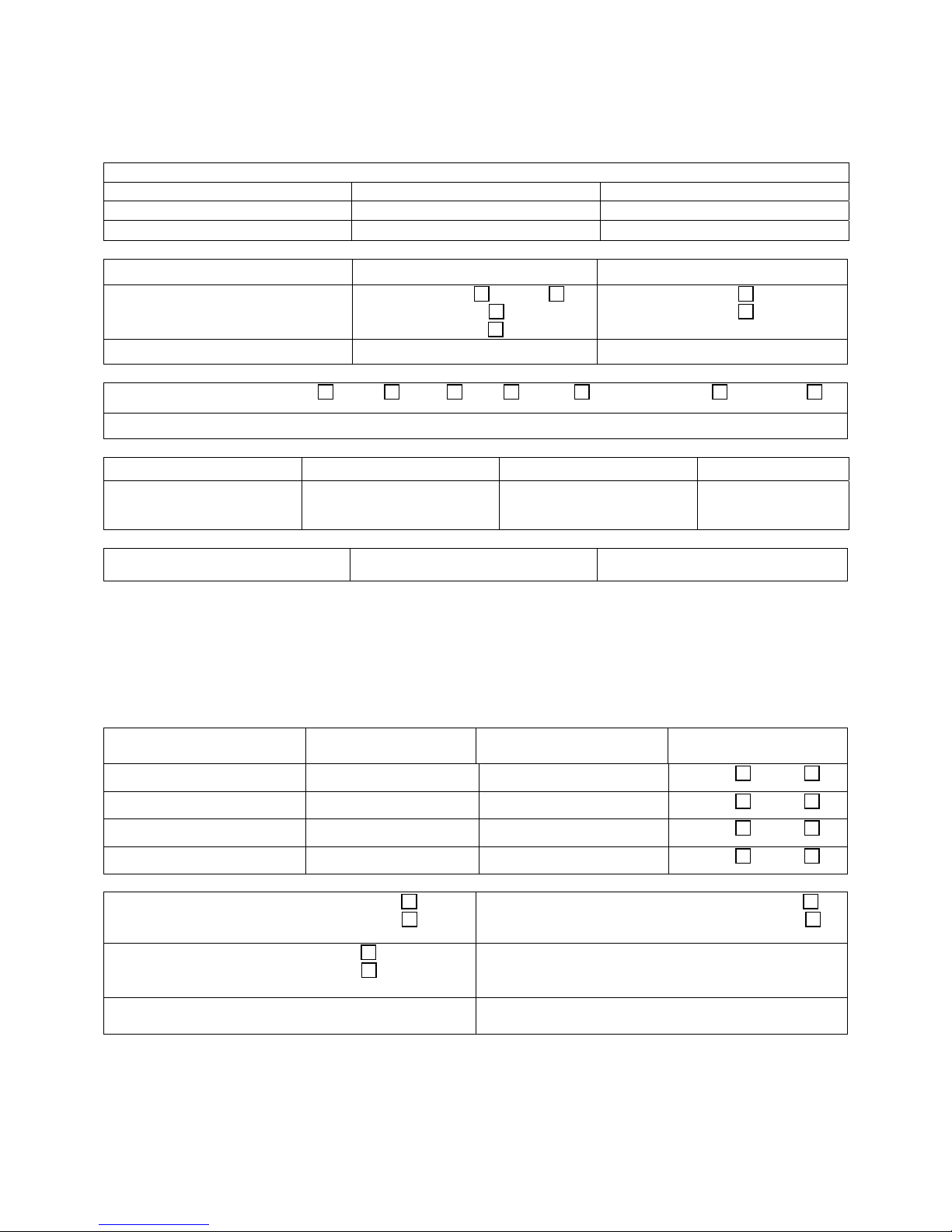
UVIC Field Test Data
Customer: Project Number: Date:
Contact Person: Phone: Second Phone:
Radio Shop: Contact: Phone:
Siren Type: S/N: Voltage:
Controller Type: Antenna: Omni Yagi
Cabinet Mounted
External Mounted
A/C Service: O.H.
U.G.
CPU Software: Program file: SMV:
Radio Information: Low Band
VHF UHF 800 Trunk 12.5 KHz 25 KHz
Radio Frequency: TX RX PL
Site: S/N: Address: Zone:
A/C voltage: Vac Battery voltage: Charger voltage:
Battery Type: Model: Manufacturer:
1. Press buttons “2” & “3” on the CPU control board simultaneously. This will calibrate the speakers and amplifiers.
2. Remove audio output lines from Amps 1-2 on the motherboard by pulling the connector out. This will remove the speakers from
the circuit.
3. Select and execute the “ STEADY “ signal. Take RMS readings while unit is performing this function. When done recording
readings, cancel the “STEADY” signal.
4. Replace the audio output connections to re-connect the speakers.
RMS VAC
Impedance Ω
Sensor State
Amp 1 VAC
Amp 1 Ω
Intrusion Sensor Pass Fail
Amp 2 VAC
Amp 2 Ω
AC Power On Pass Fail
AC Power Off Pass Fail
Mic mounted in Control Cabinet: Yes
No
Antenna connectors sealed: Yes
No
(Required for outdoor antenna installations)
Tested by: Date:
Notes:
PRE-OPERATION CHECK-OUT AND TEST
Low Battery Pass Fail
Debris removed from Control Cabinet: Yes
Field Test Data Sheet
75
No
Page 76

7. MAINTENANCE
SECTION VII
WARNING
Service and maintenance should be
performed by qualified personnel
familiar with the UVIC, associated
controls, and power sources being used
and in conjunction with the authorities
having jurisdiction.
The sound output of speakers is
capable of causing permanent hearing
damage. Use adequate hearing
protection and avoid excessive
exposure.
Before servicing or maintaining, ensure
that remote activation cannot occur and
disconnect power to the UVIC.
The UVIC series speaker controller is
designed to require a minimum amount
of maintenance. In addition, experience
has shown that all Federal Signal
products are highly reliable devices.
However, if a failure does occur, Federal
will provide technical assistance with
problems that cannot be handled
satisfactorily and promptly locally. If
assistance is desired, contact:
FWS Service Department
Signal Division
Federal Signal Corporation
2645 Federal Signal Drive
University Park, Illinois 60466
(800) 524-3021
MAINTENANCE
76
Page 77

WARNING
The sound output of speakers is
capable of causing permanent hearing
damage at short distances. Therefore,
ALWAYS wear hearing protection when
performing tests or maintenance on the
speakers.
To prevent the speakers from sounding,
always turn off the power to the UVIC at
the AC disconnect and remove any DC
power being supplied before inspecting
or maintaining the speakers.
7.1 Control Unit Preventive
Maintenance
Test the UVIC for proper operation at
least once a month. A daily test at noon,
curfew, or other selected time is
preferred. This not only enhances the
usefulness of the UVIC and verifies that
it remains ready for use when needed; it
also instills confidence in the reliability of
the system.
In order to minimize the potential for a
failure, annual inspection and
maintenance is recommended.
7.2 General Maintenance
Signal Operational Check
1. When checking for proper control
module output, unplug the terminal
strip connectors to the speakers (at
the bottom of the system
motherboard) to eliminate output
from the speaker array.
2. Activate each of the signals and
observe the signal indicators on the
control module and the amplifiers.
3. If desired, an oscilloscope or digital
multi-meter (DMM) can be
connected to the amplifier module
output terminal strip to observe the
amplifier output. This output should
be at least 67 Vrms during a signal if
the amp is programmed to run at full
power. To limit sound output, plug in
one amplifier at a time during this
test.
4. Plug all of the amplifier terminal strip
connectors to enable amplifier
outputs.
Battery Check
1. The voltage of a fully charged s et of
batteries should be approximately
27.2 VDC, and charger current
should be less than 2 Amperes. The
charger is set for 27.2 +/-0.1 VDC at
room temperature.
2. Load test the batteries per the
manufacturer’s specifications.
3. Maintain or replace the battery as
recommended by its manufacturer;
obey local or state laws governing
the disposal of lead-acid batteries.
4. Check the battery terminals for
corrosion. Clean and grease
connectors and terminals, if
necessary.
MAINTENANCE
77
Page 78

7.3 Troubleshooting
PROBLEM ACTION
1. NO RADIO DECODE A. Unit is not programmed to recognize that
particular code sequence (or) Signal is not
being received properly.
B. Verify programming is correct. Check the
received audio signal quality at the RX test
pin on the front of the control board.
2. LOW OUTPUT FROM
SPEAKERS
Check battery voltage. Also, check signal
indicators on amplifiers during a function. If
indicators are off, remove amplifier for
service.
3. FUNCTION STOPS BEFORE
NORMAL TIME-OUT
Batteries may require further charging.
Check battery voltage under load. Check
charger output.
4. LOCAL PA FEEDS BACK Lower PA volume using knob above MIC
connector.
5. LOCAL PA HAS LITTLE OR NO
OUTPUT
Hold MIC close to mouth. Increase PA
volume using knob above MIC connector.
6. BATTERIES NOT HOLDING
CHARGE
Check that charger fuses are intact and
check charger output.
Test batteries.
7. RELAY OUTPUT ON
MOTHERBOARD DOESN’T
OPERATE
Check that the relay on the system
motherboard is operating (indicated by LED
D2). Also check fuse F1 on motherboard (20
amp slo-blow)
8. RADIO PA TAKES TOO LONG
TO TIME OUT
9. LANDLINE ACTIVATION INPUTS
DO NOT FUNCTION
Check radio for proper operation of squelch.
CD LED should light while carrier is present.
Verify minimum 1- second contact closure is
applied to JP14 on the motherboard.
NOTE: For additional help contact the FWS Service Dept. at (800) 524-3021.
78
OPTIONS
Page 79

SECTION VIII
8. OPTIONS
8.1 Radio Control
The UVIC can be activated by a radio
signal when the optional radio
transceiver is incorporated into the
Control Unit. Activation by radio control
has the advantage that control lines are
not required between the control site
and the UVIC. Federal Signal offers the
controller with a full line of transceivers
built in which cover the
VHF and UHF bands.
8.2 Digital Voice Recording
Four minutes of digital voice storage is
provided as a standard feature with the
UVIC. When the Digital Voice Recording
option (model DVR) is purchased, the
UVIC will be factory programmed with
high quality voice or music recordings
as specified by the customer.
Up to 16 individual messages may be
programmed into the UVIC. Digital
Voice Messages may be activated
remotely or via the control panel
switches. To program activation codes
with Digital Voice Messages under
them, follow the instructions in the
Commander Digital System manual. It is
possible to assign codes to the functions
DIG VOICE 1 through DIG VOICE 16.
As in all sounding functions, the unit
must first be sent the ARM command
followed by one of the six DIG VOICE
commands to activate the stored
message. The only adjustment available
on the Digital Voice PCB is a
potentiometer, which adjusts the audio
output level.
8.3 UVIC25ST Option
When purchased, the UVIC25ST allows
the end-user the capability to reduce
audio output from the 70VRMS standard
to the 25VRMS standard. This option is
beneficial when deploying the
UltraVoice electronic controller in an
indoor warning application. See Section
9 for wiring details.
8.4 UVIC25SD Option
As with the UVIC25ST, the UVIC25SD
allows the end-user the capability to
reduce audio output from the 70VRMS
standard to the 25VRMS standard. The
UVIC25SD consists of a PC board with
two 400W step-down transformers
housed inside a fiberglass enclosure.
This option is needed instead of the
UVIC25ST when purchasing two UV400
amplifiers.
8.5 UVARM Option
The Audio and Relay Output module
provides three separate audio outputs
for the UltraVoice controller to interface
with other devices and systems. The
outputs consist of a balanced 33 ohm, a
balanced 600 ohm, a selectable 600
79
OPTIONS
Page 80

ohm balanced or single-ended line level
output and four SPDT relay outputs.
The level of each audio output is
independently adjustable. Each audio
and relay output is individually
addressable allowing each output to be
activated at different times.
The UVARM connects to one of the two
control card connectors on the UVIC
motherboard and is mounted on an
aluminum faceplate with mounting holes
for attaching to the UVIC card cage.
The connectors for the ARO are located
on the front of the card and extend
through openings in the faceplate.
SFCDWARE is used to assign Audio
and Relay outputs to functions. Audio
and Relay outputs may be selectively
programmed to be active together or
individually with any control function.
The outputs may be programmed to
stay on for the duration of the function,
or latch on until turned off.
8.6 UVLOC Option
An optional Local Operation Console
(model UVLOC) enables users to
control the UVIC from an easy to use
pushbutton control panel. The panel is
connected to the UVIC with a standard
CAT5 network cable and may be
located up to ½ mile away from the
UVIC controller. The UVLOC is remotely
powered from the UVIC and requires no
local power source of it’s own. The
panel measures only 10” x 4.75” x 3” (L
x W x D) and is easily wall mounted.
The UVLOC provides control for 7 digital
recordings: Live P.A., P.A. Recording
from an integrated microphone,
Recorded P.A. Playback, and two
Auxiliary user programmable functions.
8.7 Installation of User Supplied
Radio Receivers
CAUTION
Improper installation of radio control
equipment may cause the speakers to
malfunction or operate intermittently.
Installation must only be performed by
experienced radio technicians who have
thoroughly read this manual.
1. TUNING - Tune the radio receiver to
the manufacturer's specifications.
2. POWER - Determine the radio power
requirements. The ULTRAVOICE
control panel provides +12VDC on
the RADIO connector on the front
panel, as shown below;
RADIO Connector, 8 pin MOD jack;
1. Receive Audio, 150mV – 10V
2. Transmit Audio, 50mV - 3V
p-p
p-p
3. Carrier Detect - active low
4. PTT
5. +12VDC
6. GND
7. +12VDC
8. GND
This voltage source must not be used
for radios, which draw more than 1.5
Amps of current in transmit. Use both
grounds and both +12VDC connections
for current handling. If a higher current
output is required, a 24VDC - 12VDC
voltage converter must be purchased.
This converter is provided with the UVIC
series models. Do not use one of the
12VDC batteries to run the radio
equipment.
80
OPTIONS
Page 81

1. AUDIO – The ULTRAVOICE
controller Receive Audio Input
should be connected to the deemphasized Audio Output of the
radio. Use shielded audio grade
cable and keep wire runs as short as
possible. The Receive Audio level
can vary from 150mV – 3V
p-p
unclipped.
2. The Transmit Audio Output is
adjustable from 50mV - 3V
p-p
.
3. C.D. - The carrier detect signal from
the radio must pull to ground when
active. The radio carrier detect signal
is useful for controlling live PA.
When the C.D. signal is removed
from the controller for over 5
seconds, the controller will
automatically cancel the PA function
eliminating the need to broadcast the
cancel tones over the speakers.
4. PTT – The PTT output pulls to
ground when active to key the radio.
5. RX and TX Audio – Adjust the RX
and TX Audio levels as described in
section 6.
81
OPTIONS
Page 82

82
SECTION IX
9. Final Assembly Drawing and Parts List
Figure 9.1 – UVIC Final Assembly and Parts List (Page 1 of 2)
Page 83

83
Figure 9.1 – UVIC Final Assembly and Parts List (Page 2 of 2)
Page 84

Figure 9.2 – UVIC25ST Wiring Detail
UVIC Final Assembly and Parts List
84
 Loading...