

Federal Signal Corporation Pathfinder Siren Series Installation And Maintenance Manual
Pathnder® Expansion Module
18-Channel Expansion Module, Taillight Flasher,
Pathnder® Siren Series Installation and
25500587B
B0 0919
Printed in U.S.A.
© Copyright 2019 Federal Signal Corporation
Maintenance Manual

Limited Warranty
This product is subject to and covered by a limited warranty,
a copy of which can be found at www.fedsig.com/SSG-Warranty.
A copy of this limited warranty can also be obtained by written
request to Federal Signal Corporation, 2645 Federal Signal Drive,
University Park, IL 60484, email to info@fedsig.com or
call +1 708-534-3400.
This limited warranty is in lieu of all other warranties, express or
implied, contractual or statutory, including, but not limited to the
warranty of merchantability, warranty of tness for a particular
purpose and any warranty against failure of its essential purpose.
2645 Federal Signal Drive
University Park, Illinois 60484
www.fedsig.com
Customer Support
Police/Fire-EMS: 800-264-3578 • +1 708 534-3400
Work Truck: 800-824-0254 • +1 708 534-3400
Technical Support 800-433-9132 • +1 708 534-3400
Allegiant, Integrity, Navigator, Rumbler, SignalMaster, SpectraLux, and Valor are registered trademarks
of Federal Signal Corporation

Contents
Safety Messages for Installers and Operators .........................................................................5
Safety Messages to Installers of Sound/Light Systems ...........................................................................5
Safety Messages to Operators of Sound/Light Systems ........................................................................ 7
An Overview of the Pathnder Expansion Module ..................................................................9
Second Expansion Module in a System ...................................................................................................... 9
Specifications ....................................................................................................................................................10
Expansion Module Kit Contents ...................................................................................................................10
Wiring the Pathnder Expansion Module ............................................................................... 11
General Guidelines for Wiring the Expansion Module on a Vehicle ....................................................11
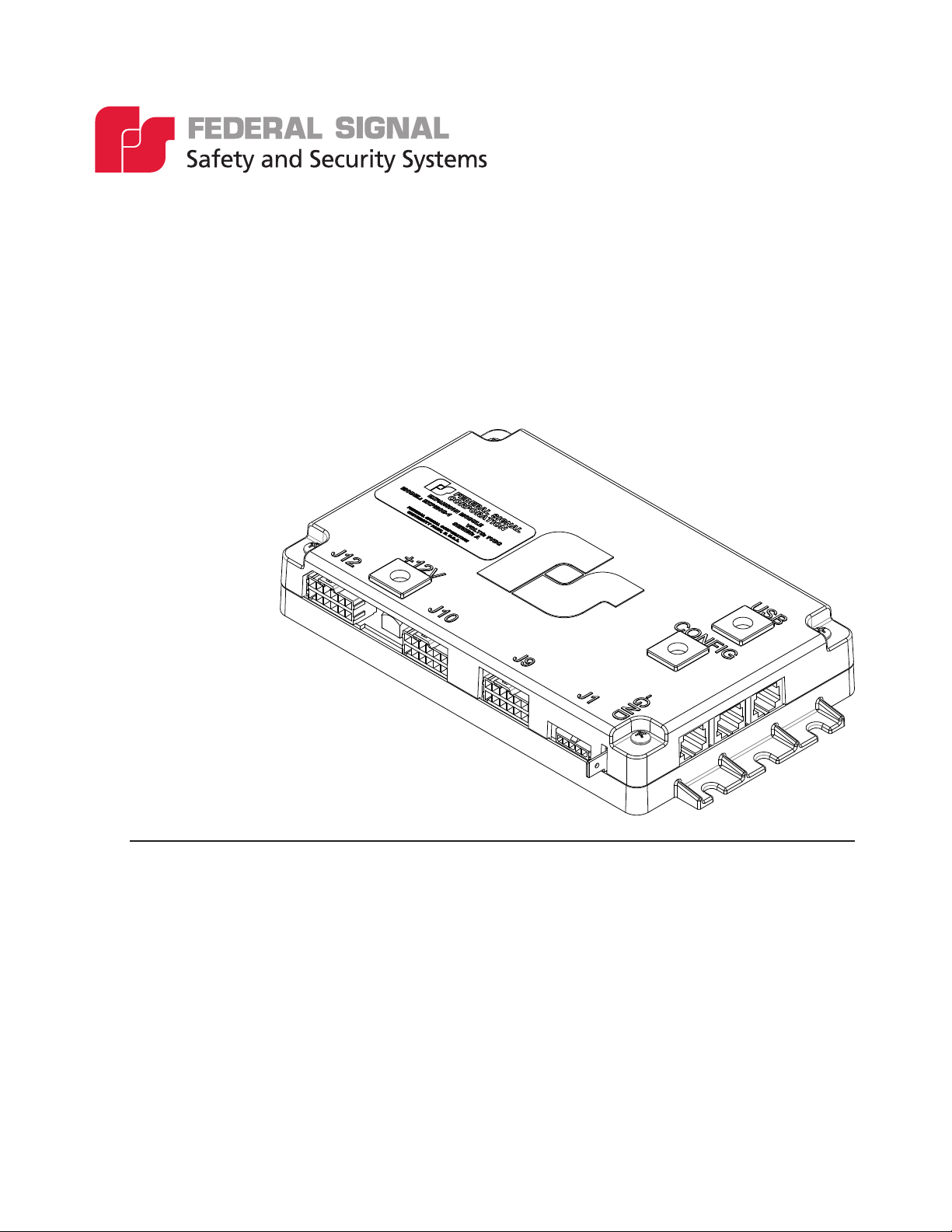
Overview of the Pathfinder Connections ....................................................................................................11
Convergence Network Ports .........................................................................................................................11
Expansion Module Relay Outputs ................................................................................................................12
System Power ......................................................................................................................................12
Mounting the Pathnder Expansion Module ..........................................................................16
Mounting the Expansion Module .................................................................................................................16
Programming the Pathnder Expansion Module ...................................................................17
Getting Technical Support ........................................................................................................19
Getting Repair Service ..............................................................................................................19
Ordering Replacement Parts ....................................................................................................19
Downloading Pathnder Conguration Software ..................................................................19
Tables
Table 1 DIP Switch Positions ................................................................................................................................9
Table 2 Specifications ......................................................................................................................................... 10
Table 3 Expansion Module ................................................................................................................................ 10
Table 4 J10 Blackout Relays ...............................................................................................................................13
Table 5 J9 Blackout Relays and Flashing Outputs .......................................................................................14
Table 6 J12 Flashing Outputs and 20 Amp Outputs ....................................................................................14
EXPMOD-2 Pathnder® Expansion Module
Federal Siglnal www.fedsig.com
3

Figures
Figure 1 DIP Switch ................................................................................................................................................. 9
Figure 2 Relays .......................................................................................................................................................12
Figure 3 Convergence Network Serial Ports ..................................................................................................12
Figure 4 Bottom View ...........................................................................................................................................13
Figure 5 Circuit .......................................................................................................................................................15
Figure 6 Mounting the Module ........................................................................................................................... 17
Figure 7 Pathfinder Expansion Module Page .................................................................................................18
Figure 8 Pathfinder Expansion Module Programming .................................................................................19
4
EXPMOD-2 Pathnder® Expansion Module
Federal Siglnal www.fedsig.com

Safety Messages for Installers and Operators
Safety Messages for Installers and Operators
For your safety, read and understand this manual thoroughly before installing,
operating, and servicing the Pathfinder siren amplifier/relay module. The safety
messages presented in this chapter and throughout the manual are reminders
to exercise extreme care at all times. In addition, read and understand the
safety instructions to installers (doc. no. 256A692), and keep it close at hand for
reference.
To download copies of this manual, go to www.fedsig.com or call the Federal Signal
Service Department at 1-800-433-9132 (708-534-3400) 7 a.m. to 5 p.m., Monday
through Friday (CT).
Safety Messages to Installers of Sound/Light Systems
People’s lives depend on your proper installation and servicing of Federal Signal
products. It is important to read and follow all instructions shipped with this
product. Listed below are some other important safety instructions and precautions
you should follow:
Before Installation
Qualifications
• To properly install an electronic siren, you must have a good understanding
of automotive electrical procedures and systems, along with proficiency in
the installation and service of safety warning equipment. Always refer to
the vehicle’s service manuals when performing equipment installations on a
vehicle.
Sound Hazards
• Your hearing and the hearing of others, in or close to your emergency vehicle,
could be damaged by loud sounds. This can occur from short exposures to very
loud sounds, or from longer exposures to moderately loud sounds. For hearing
conservation guidance, refer to federal, state, or local recommendations. OSHA
Standard 1910.95 oers guidance on “Permissible Noise Exposure.”
• All eective sirens and horns produce loud sounds (120 dB) that may cause
permanent hearing loss. Always minimize your exposure to siren sound and
wear hearing protection. Do not sound the siren indoors or in enclosed areas
where you and others will be exposed to the sound.
• Federal Signal siren amplifier/relay modules and speakers are designed to
work together as a system. Combining a siren and speaker from dierent
manufacturers may reduce the warning eectiveness of the siren system and
may damage the components. You should verify or test your combination to
make sure the system works together properly and meets federal, state and
local standards or guidelines.
During Installation
• Do NOT get metal shavings inside the product. Metal shavings in the product
can cause the system to fail. If drilling must be done near the unit, place an ESD
Installation and Maintenance Manual
Federal Signal www.fedsig.com
5

Safety Messages for Installers and Operators
approved cover over the unit to prevent metal shavings from entering the unit.
Inspect the unit after mounting to be sure there are no shavings present in or
near the unit.
• Do NOT connect this system to the vehicle battery until ALL other electrical
connections are made, mounting of all components is complete, and you have
verified that no shorts exist. If wiring is shorted to vehicle frame, high current
conductors can cause hazardous sparks, resulting in electrical fires or flying
molten metal.
• Ensure that the siren amplifier/relay module and speaker(s) in your installation
have compatible wattage ratings.
• In order for the electronic siren to function properly, the ground connection
must be made to the NEGATIVE battery terminal.
• Sound output will be severely reduced if any objects are in front of the speaker.
If maximum sound output is required for your application, you should ensure
that the front of the speaker is clear of any obstructions.
• Install the speaker(s) as far forward on the vehicle as possible, in a location that
provides maximum signaling eectiveness and minimizes the sound reaching
the vehicle’s occupants. Refer to the National Institute of Justice guide 500-00
for further information.
• Mounting the speakers behind the grille will reduce the sound output and
warning eectiveness of the siren system. Before mounting speakers behind
the grille, make sure the vehicle operators are trained and understand that this
type of installation is less eective for warning others.
• Sound propagation and warning eectiveness will be severely reduced if the
speaker is not facing forward. Carefully follow the installation instructions and
always install the speaker with the projector facing forward.
• Do NOT install the speaker(s) or route the speaker wires where they may
interfere with the operation of airbag sensors.
• Installation of two speakers requires wiring speakers in phase.
• Never attempt to install aftermarket equipment, which connects to the vehicle
wiring, without reviewing a vehicle wiring diagram available from the vehicle
manufacturer. Ensure that your installation will not aect vehicle operation and
safety functions or circuits. Always check vehicle for proper operation after
installation.
• Do NOT install equipment or route wiring or cord in the deployment path of an
airbag.
• If a vehicle seat is temporarily removed, verify with the vehicle manufacturer if
the seat needs to be recalibrated for proper airbag deployment.
6
• Locate the control head so the vehicle, controls, and microphone can be
operated safely.
EXPMOD-2 Pathnder® Expansion Module
Federal Signal www.fedsig.com
 Loading...