

Page 1
25500463
B0 0818
Printed in U.S.A.
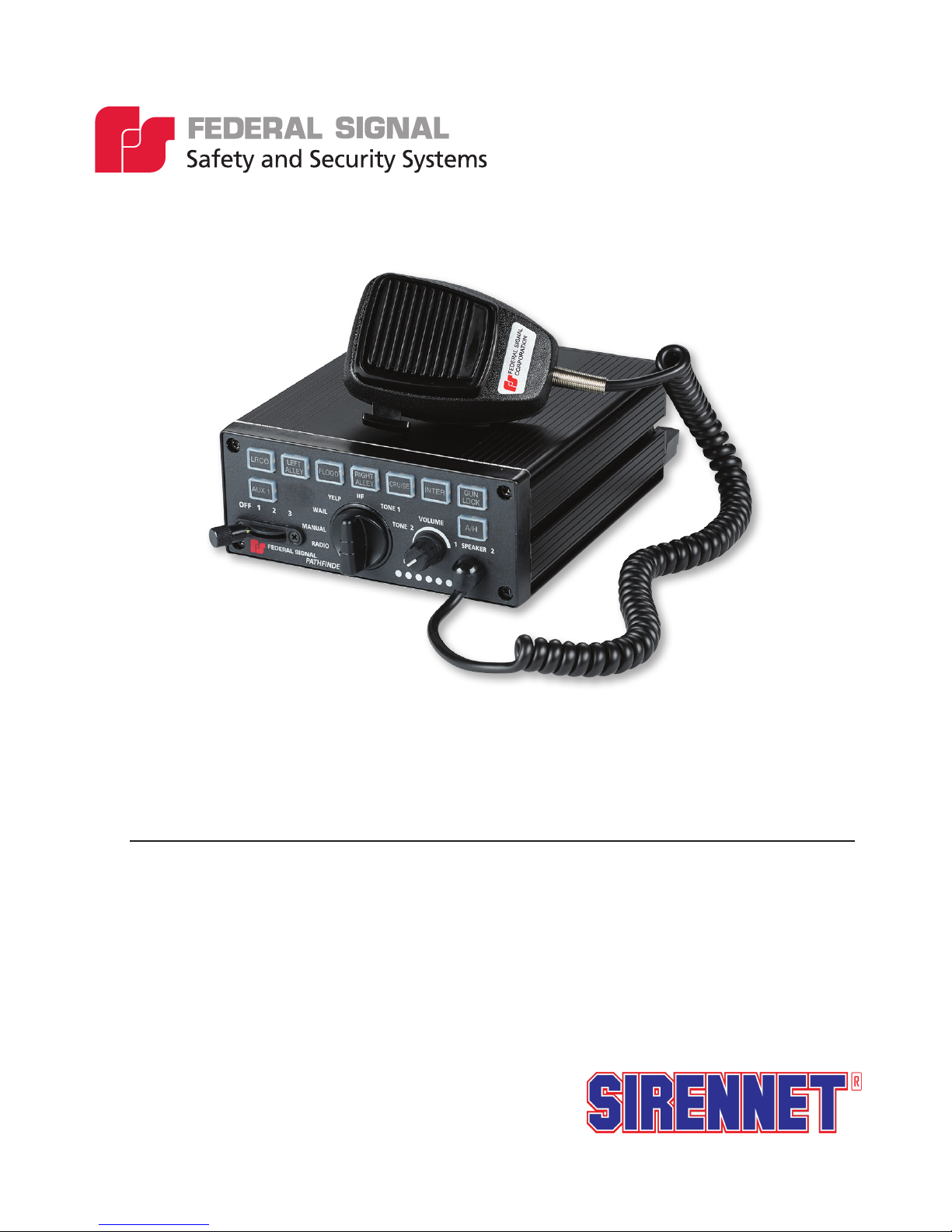
PathnderTM
Installation and
Maintenance Instructions
Distributed By:
Page 2

Limited Warranty
This product is subject to and covered by a limited warranty,
a copy of which can be found at www.fedsig.com/SSG-Warranty.
A copy of this limited warranty can also be obtained by written
request to Federal Signal Corporation, 2645 Federal Signal Drive,
University Park, IL 60484, email to info@fedsig.com or
call +1 708-534-3400.
This limited warranty is in lieu of all other warranties, express or
implied, contractual or statutory, including, but not limited to the
warranty of merchantability, warranty of tness for a particular
purpose and any warranty against failure of its essential purpose.
2645 Federal Signal Drive
University Park, Illinois 60484
www.fedsig.com
Customer Support
Police/Fire-EMS: 800-264-3578 • +1 708 534-3400
Work Truck: 800-824-0254 • +1 708 534-3400
Technical Support 800-433-9132 • +1 708 534-3400
Allegiant, Integrity, Navigator, Rumbler, SignalMaster, SpectraLux, and Valor are registered trademarks of Federal Signal Corporation
Page 3

Contents
Chapter 1 Safety Messages for Installers and Operators ......................................................5
Safety Messages to Installers of Sound/Light Systems .....................................................................5
Safety Messages to Operators of Sound/Light Systems ....................................................................8
Chapter 2 An Overview of the Pathnder .............................................................................. 10
Siren, PA, and Speakers ...................................................................................................................10
Lightbars and SignalMasterTM Control .............................................................................................10
FS Vehicle Integration ...................................................................................................................... 11
Programmable Solid-State Auxiliary Relays ...................................................................................11
Programmable Input Circuits ........................................................................................................... 11
LED Indicators and Visual Diagnostics ........................................................................................... 11
System Specications ......................................................................................................................12
Siren Specications ..........................................................................................................................12
Relay Specications .........................................................................................................................12
Pathnder Kit Contents ....................................................................................................................13
Chapter 3 Wiring the Pathnder .............................................................................................15
General Guidelines for Wiring the Pathnder on a Vehicle .............................................................15
Overview of the Pathnder Connections .........................................................................................17
Convergence Network Ports .......................................................................................................17
Relay Outputs .............................................................................................................................17
General Purpose Inputs ...............................................................................................................17
Park Input ...................................................................................................................................17
Horn Ring Transfer .....................................................................................................................18
Speaker Connections ..................................................................................................................18
Speaker Diagnostics ...................................................................................................................19
Radio Re-Broadcast ....................................................................................................................19
FS Vehicle Integration ................................................................................................................19
Ignition Input ..............................................................................................................................19
System Power .............................................................................................................................19
Chapter 4 Mounting the Pathnder ........................................................................................ 21
Mounting the Siren ..........................................................................................................................23
Mounting the Control Head (PF200R) ............................................................................................23
Chapter 5 Testing the Pathnder Installation ........................................................................25
Pathnder
TM
3
Page 4

Contents
Chapter 6 Control Head Legends and Safety Messages .....................................................28
Applying the Replaceable Control Head Legends ...........................................................................28
Distributing the Safety Message Card .............................................................................................29
Applying the Siren Safety Labels in the Vehicle .............................................................................29
Chapter 7 Safety Messages to Personnel Servicing Federal Electronic Sirens ................30
Chapter 8 Servicing the Pathnder ........................................................................................ 31
Replacing the Slide Switch ..............................................................................................................31
Getting Technical Support and Service ............................................................................................34
Returning a Product to Federal Signal .............................................................................................35
Tables
Table 2.1 PF200 Kit Contents .............................................................................................................13
Table 2.2 PF200R Kit Contents ...........................................................................................................14
Table 5.1 Pathnder Switch Default Programming .............................................................................26
Table 5.2 Pathnder Button Default Programming .................................................................................... 26
Table 5.3 Pathnder Input Default Programming ....................................................................................... 27
Table 8.1 Service Parts ........................................................................................................................33
Figures
Figure 3.1 100W Single Tone and 200W Dual Tone Siren Connections ............................................ 16
Figure 3.2 100W Siren with Integrated Rumbler ................................................................................16
Figure 3.3 Battery Connections...........................................................................................................20
Figure 4.1 Pathnder Dimensions .......................................................................................................22
Figure 4.2 Mounting Hardward Dimensions ......................................................................................22
Figure 4.3 Bail Bracket Assembly ........................................................................................................ 23
Figure 4.4 Bracket Attached to Back of Control Head ........................................................................24
Figure 4.5 Brackets Attached to Control Head and Mounting Surface ............................................... 24
Figure 5.1 Pathnder Default Programming .......................................................................................25
Figure 6.1 Installing the Control Head Labels ....................................................................................28
Figure 6.2 Safety Message Card (left) and Siren Safety Labels (right) ..............................................29
Figure 8.1 Keypad Removal ................................................................................................................31
Figure 8.2 Slide Switch Replacement .................................................................................................32
4
Pathnder
TM
Page 5

CHAPTER 1
Safety Messages for Installers and Operators
For your safety, read and understand this manual thoroughly before installing, operating, and
servicing the Pathnder siren amplier/relay module. The safety messages presented in this chapter
and throughout the manual are reminders to exercise extreme care at all times. In addition, read and
understand the safety instructions to installers (doc. no. 256A692), and keep it close at hand for
reference.
To download copies of this manual, go to www.fedsig.com or call the Federal Signal Service
Department at 1-800-433-9132 (708-534-3400) 7 a.m. to 5 p.m., Monday through Friday (CT).
Safety Messages to Installers of Sound/Light Systems
People’s lives depend on your proper installation and servicing of Federal Signal products. It is
important to read and follow all instructions shipped with this product. In addition, listed below are
some other important safety instructions and precautions you should follow:
Before Installation
Qualications
• To properly install an electronic siren, you must have a good understanding of automotive
electrical procedures and systems, along with prociency in the installation and service of safety
warning equipment. Always refer to the vehicle’s service manuals when performing equipment
installations on a vehicle.
Sound Hazards
• Your hearing and the hearing of others, in or close to your emergency vehicle, could be damaged
by loud sounds. This can occur from short exposures to very loud sounds, or from longer
exposures to moderately loud sounds. For hearing conservation guidance, refer to federal, state,
or local recommendations. OSHA Standard 1910.95 offers guidance on “Permissible Noise
Exposure.”
• All effective sirens and horns produce loud sounds (120 dB) that may cause permanent hearing
loss. Always minimize your exposure to siren sound and wear hearing protection. Do not sound
the siren indoors or in enclosed areas where you and others will be exposed to the sound.
Pathnder
TM
5
Page 6

Chapter 1: Safety Messages for Installers and Operators
• Federal Signal siren amplier/relay modules and speakers are designed to work together as a
system. Combining a siren and speaker from different manufacturers may reduce the warning
effectiveness of the siren system and may damage the components. You should verify or test your
combination to make sure the system works together properly and meets federal, state and local
standards or guidelines.
During Installation
• Do NOT get metal shavings inside the product. Metal shavings in the product can cause the
system to fail. If drilling must be done near the unit, place an ESD approved cover over the unit to
prevent metal shavings from entering the unit. Inspect the unit after mounting to be sure there are
no shavings present in or near the unit.
• Do NOT connect this system to the vehicle battery until ALL other electrical connections are
made, mounting of all components is complete, and you have veried that no shorts exist. If
wiring is shorted to vehicle frame, high current conductors can cause hazardous sparks resulting in
electrical res or ying molten metal.
• Be sure the siren amplier/relay module and speaker(s) in your installation have compatible
wattage ratings.
• In order for the electronic siren to function properly, the ground connection must be made to the
NEGATIVE battery terminal.
• Sound output will be severely reduced if any objects are in front of the speaker. If maximum
sound output is required for your application, you should ensure that the front of the speaker is
clear of any obstructions.
• Install the speaker(s) as far forward on the vehicle as possible, in a location which provides
maximum signaling effectiveness and minimizes the sound reaching the vehicle’s occupants.
Refer to the National Institute of Justice guide 500-00 for further information.
• Mounting the speakers behind the grille will reduce the sound output and warning effectiveness of
the siren system. Before mounting speakers behind the grille, make sure the vehicle operators are
trained and understand that this type of installation is less effective for warning others.
• Sound propagation and warning effectiveness will be severely reduced if the speaker is not facing
forward. Carefully follow the installation instructions and always install the speaker with the
projector facing forward.
• Do NOT install the speaker(s) or route the speaker wires where they may interfere with the
operation of airbag sensors.
• Installation of two speakers requires wiring speakers in phase.
• Never attempt to install aftermarket equipment, which connects to the vehicle wiring, without
reviewing a vehicle wiring diagram available from the vehicle manufacturer. Insure that your
installation will not affect vehicle operation and safety functions or circuits. Always check vehicle
for proper operation after installation.
6
Pathnder
TM
Page 7

Chapter 1: Safety Messages for Installers and Operators
• Do NOT install equipment or route wiring or cord in the deployment path of an airbag.
• If a vehicle seat is temporarily removed, verify with the vehicle manufacturer if the seat needs to
be recalibrated for proper airbag deployment.
• Locate the control head so the vehicle, controls, and microphone can be operated safely.
• When drilling into a vehicle structure, be sure that both sides of the surface are clear of anything
that could be damaged. All drilled holes should be deburred and all sharp edges should be
smoothed. All wires going through drilled holes should be protected by a grommet or convolute/
split-loom tubing. Additionally, all exterior drilled holes must be sealed with Motorcraft seam
sealer T-A-2-B or equivalent to prevent the potential exposure to carbon monoxide or other
potentially harmful fumes. Failure to observe this warning could cause serious injury or death.
After Installation
• After installation, test the siren and light system to ensure that it is operating properly.
• Test all vehicle functions, including horn operation, vehicle safety functions and vehicle light
systems, to ensure proper operation. Ensure that installation has not affected vehicle operation or
changed any vehicle safety function or circuit.
• After testing is complete, provide a copy of these instructions to the instructional staff and all
operating personnel.
• File these instructions in a safe place and refer to them when maintaining or reinstalling the
product.
Failure to follow all safety precautions and instructions may result in property damage, serious injury,
or death.
RETAIN AND REFER TO THESE MESSAGES
Pathnder
TM
7
Page 8

Chapter 1: Safety Messages for Installers and Operators
Safety Messages to Operators of Sound/Light Systems
People’s lives depend on your safe operation of Federal Signal products. It is important to read and
follow all instructions shipped with the products. In addition, listed below are some other important
safety instructions and precautions you should follow:
• Do not attempt to activate or de-activate the light system control while driving in a hazardous
situation.
• Although your warning system is operating properly, it may not be completely effective. People
may not see or heed your warning signal. You must recognize this fact and continue driving
cautiously.
• Also, situations may occur which obstruct your warning signal when natural and man-made
objects are between your vehicle and others, such as raising your hood or trunk lid. If these
situations occur, be especially careful.
• All effective sirens and horns produce loud sounds that may cause, in certain situations, permanent
hearing loss. You and your passengers should consider taking appropriate safety precautions, such
as wearing hearing protection.
• In order to be an effective warning device, this product produces bright light that can be hazardous
to your eyesight when viewed at a close range. Do not stare directly into this lighting product at a
close range or permanent damage to your eyesight may occur.
• It is important that you fully understand how to safely operate this warning system before use.
• You should only operate your vehicle and its light/sound system in accordance with your
department’s Standard Operating Procedures.
• If a selected function does not perform properly or if any of the lamps remain illuminated when
the control is off, disconnect the power connector from the control unit and contact the nearest
service center.
• At the start of your shift, you should ensure that the entire warning light system and the siren
system is securely attached and operating properly.
• The effectiveness of an interior mounted warning light depends on the clarity, the tinting, and the
angle of the glass it is being placed behind. Tinting, dirt, defects, and steeply angled glass reduce
the light output of the warning light. This may reduce the effectiveness of the light as a warning
signal. If your vehicle has dirty, tinted, or steeply angled glass, use extra caution when driving
your vehicle or blocking the right of way with your vehicle.
• Suction cup mounting is for temporary applications only. The unit should be removed from the
window and stored securely when not in use. Temperature changes and sunlight can cause suction
cups to lose holding power. Periodically check the unit to be sure the suction cups have a rm grip
on the mounting surface. An improperly secured light could fall off of the vehicle causing injury
and damage.
8
Pathnder
TM
Page 9

Chapter 1: Safety Messages for Installers and Operators
• The holding power of magnetic mounting systems is dependent upon surface nish, surface
atness, and thickness of the steel mounting surface.
Therefore, to promote proper magnetic mounting:
✓
The mounting surface and magnets must be kept clean, dry, and free of foreign particles that
prevent good surface contact.
✓
Ensure that the mounting surface is at.
✓
A magnet mounting system should not be used on vehicles with vinyl tops.
✓
To prevent the light assembly from sliding on mounting surface, avoid quick acceleration and
hard stops.
Failure to follow these precautions may result in property damage, serious injury, or death.
RETAIN AND REFER TO THESE MESSAGES
Pathnder
TM
9
Page 10

CHAPTER 2
An Overview of the Pathnder
The Pathnder siren is a full-featured, programmable electronic siren and light control system. State-
of-the-art microprocessor technology is used to create a system with a small, compact siren system
that can be installed under the dashboard (PF200, Self -Contained), in the trunk or under the seat
(PF200R, Remote) of any vehicle with a 12 V or 24 V negative ground system. The Pathnder siren
uses class D amplier technology to provide two independent 100W channels of audio, for a total
of 200W, without the need for a large and heavy transformer. The module provides the automatic,
simultaneous light and siren activation required by some jurisdictions. A security gun timer is also
provided to minimize the possibility of unauthorized shotgun release. The module has two easily
accessible Convergence Network serial ports that can connect a remote mounted control head and/
or any serially-controlled Federal Signal product. The siren also has FS Vehicle Integration to allow
for various events a vehicle to integrate with siren/lighting control. A variety of system features
can be programmed with the Convergence Network Conguration Software from a computer via a
USB cable that connects the siren amplier. System features include ash patterns, siren tones, and
momentary, push-on/push-off, timed relay operation, as well as vehicle events. Programming does
not require disassembling or removing any hardware from the vehicle.
Siren, PA, and Speakers
The Pathnder produces wail, yelp, priority, and as well as an air horn sound by default. The horn-
ring transfer feature enables the driver to control siren tones by pressing the horn button. Public
address is available with the Federal Signal microphone, which is included with the system. Radio
rebroadcast is also available. The Pathnder can drive one or two 11-ohm impedance, 100 W
speakers. The two 11-ohm impedance, 100 W speakers have separate wires that allow the Pathnder
to provide dual siren tones. Alternatively, the Pathnder can drive one 11-ohm impedance, 100
W speaker on one channel, and two Rumbler speakers on the second channel to provide Rumbler
integration, without the need for a secondary external amplier.
Lightbars and SignalMasterTM Control
Compatible lightbars include full featured, serially-controlled Federal Signal Legend®, Valor®,
TM
Allegiant
lightbars. In addition, ash rates and patterns, lightbar dimming, external SignalMaster control and
other options can be programmed with the Convergence Network Conguration Software.
, Navigator®, and Integrity® as well as the SpectraLux ILS Series of interior-mounted
10
Pathnder
TM
Page 11

Chapter 2: An Overview of the Pathnder
FS Vehicle Integration
The Pathnder siren includes the capability to integrate with the existing vehicle CAN bus. The
FS Vehicle Integration uses a vehicle specic cable (not included) to seamlessly integrate with the
vehicle. Vehicle events can be programmed with the Convergence Network Conguration Software to
interface with the lighting/siren control. The Convergence Network Conguration Software contains
the latest list of events supported based on model, make and year of the vehicle.
Programmable Solid-State Auxiliary Relays
The Pathnder has 12 solid-state relays: ve 10A active high solid-state relays: one 10 A high-low and
six 5 A high. The maximum output current for each relay can be set with the Convergence Network
Conguration Software.
Programmable Input Circuits
The Pathnder has connections for four general purpose input circuits, plus dedicated inputs for
park, horn and ign. Ignition is an active-high only input, while all other inputs are programmable for
active-high or active-low. The inputs are most commonly used for switches that send a signal to the
siren when a condition in the vehicle changes.
LED Indicators and Visual Diagnostics
All buttons on the control head glow when the system is on. Pressed buttons turn bright to indicate
that the function they control is active. The buttons are programmable for red or blue backlighting.
LEDs on the keypad mimic these active SignalMaster patterns: Left, Right, Center-Out, and Warn
patterns. An LED glows over the position in which the slide switch is placed. Diagnostic LEDs for
speaker fault detection are also available and are programmable.
Pathnder
TM
11
Page 12

Chapter 2: An Overview of the Pathnder
System Specications
Input Voltage 11 Vdc to 28 Vdc
Polarity Negative ground only
Operating Temperature Range -40 °C to +80 °C (all relays at 50 percent power)
Standby Current Less than 0.1 A
Max Input Current 75 A (siren and relays)
Dimensions:
PF200 (Self Contained Siren)
Height 2.5 in (6.4 cm)
Width 6.0 in (15.2 cm)
Length 8.4 in (21.3 cm)
Net Weight 3.9 lb (1.77 kg)
Siren Specications
Speakers One or two 100 W, 11-ohm speakers or
One 100 W, 11-ohm speaker and two Rumbler speakers
Operating Current 100 W - One 11-ohm speaker – 8 A
200 W - Two 11-ohm speakers – 16 A
(13.6 V battery, No Relays active)
Frequency Range 182 to 1600 Hz
Nominal Cycle Rate Wail: 12 cycles per minute
Yelp: 180 cycles per minute
Priority: 370 cycles per minute
High-Low: 60 cycles per minute
Nominal Voltage Output 64 V peak-to-peak (siren tones)
Audio Response 300 Hz to 3,000 Hz ± 3 dB
Siren Tone Compliances SAE J1849 JUL89
Relay Specications
Relays 1-5 10 A (active high)
Relays 6 10 A (active high or active low)
Relays 7-12 5 A (active high)
12
Pathnder
TM
Page 13

Chapter 2: An Overview of the Pathnder
Pathnder Kit Contents
Table 2.1 and Table 2.2 list the parts included with the kit. After unpacking the kit, examine it for
damage that may have occurred in transit. If the product has been damaged, le a claim immediately
with the carrier stating the extent of damage. Carefully check all envelopes, shipping labels, and tags
before removing or destroying them. Ensure all parts in the packing list are included in the shipment.
If any parts are missing, call Federal Signal Customer Support at 1-800-264-3578, 7 a.m. to 5 p.m.,
Monday through Friday, Central Time.
Table 2.1 PF200 Kit Contents
Qty. Description Part Number
1 100/200-Watt Siren/Light Controller, Self-Cont 862302144
1 Keypad Legend Stickers 8572294
1 Bracket, Bail, Pathnder 862302132
1 Cable Assy, RS485, 25ft 1751357-02
1 Wire Assy, Relay, Pathnder 17501359
1 Wire Assy, I/O, Pathnder 17501360
1 Cable, USB 2.0, A male to Mini-B 17501813
1 Term, #8, 6 Awg 19001363
1 Kit, Hardware, Pathnder 77700765
Siren Mount Kit Contains:
2 Bolt, Carriage, 1/4-20, SS 7004A020-12
2 Nut, Ext Keps, 1/4-20, Stl 7058A005
2 Washer, Flat, 1/4 7072A028
2 Screw, Pan, Sems, M4 70000451-06
2 Lockwasher, Int Tth, 1/4 7075A016
Pathnder
TM
13
Page 14

Chapter 2: An Overview of the Pathnder
Table 2.2 PF200R Kit Contents
Qty. Description Part Number
1 100/200-Watt Amplier, Pathnder 862302662
1 Control Head, Remote, PF200R, Pathnder 862302151
1 Keypad Legend Stickers 8572294
1 Dynamic Microphone with Mod 258B577-03
1 Bracket, Bail, Pathnder 862302132
2 Bracket, Mtg. Control, Smart 85361065
1 Cable Assy, RS485, 25ft 1751357-02
1 Wire Assy, Relay, Pathnder 17501359
1 Wire Assy, I/O, Pathnder 17501360
1 Cable, USB 2.0, A male to Mini-B 17501813
1 Term, #8, 6 Awg 19001363
1 Kit, Hardware, Pathnder 77700765
Siren Mount Kit Contains:
2 Bolt, Carriage, 1/4-20, SS 7004A020-12
2 Nut, Ext Keps, 1/4-20, Stl 7058A005
2 Washer, Flat, 1/4 7072A028
2 Screw, Pan, Sems, M4 70000451-06
2 Lockwasher, Int Tth, 1/4 7075A016
1 Kit, Hardware, Control Head, Pathnder 77700992
Control Head Kit Contains:
2 Screw, 6-32, Pan HD, Phil 7000A404-05
2 Bolt, Carriage, 1/4-20, SS 7004A020-12
2 Screw, #10 TYP B, Pan Torx, Stl, Blk Zn 7011246-08
2 Washer, Flat, 1/4 7072A028
2 Lockwasher, Split Stl #6 Screw 7074A001
2 Lockwasher, Ext Tth, 1/4 7075A007
14
Pathnder
TM
Page 15

CHAPTER 3
Wiring the Pathnder
General Guidelines for Wiring the Pathnder on a Vehicle
HIGH CURRENT ARCING: Do not connect this system to the vehicle battery until
ALL other electrical connections are made and you have veried that no shorts
exist. High current conductors can cause hazardous sparks or burning wire
resulting in electrical res.
DRILLING PRECAUTIONS: When drilling into a vehicle structure, be sure that
both sides of the surface are clear of anything that could be damaged. All drilled
holes should be deburred and all sharp edges should be smoothed. All wires
going through drilled holes should be protected by a grommet or convolute/
split-loom tubing. Additionally, all exterior drilled holes must be sealed with
Motorcraft seam sealer T-A-2-B or equivalent to prevent the potential exposure
to carbon monoxide or other potentially harmful fumes. Failure to observe this
warning could cause serious injury or death.
Before permanently installing the Pathnder system, plan all wire routings and select the mounting
locations for the siren amplier/relay module. Read and understand all instructions included with
related equipment before installing it. Ensure that all wiring is protected from damage during normal
operation of the vehicle and away from any sharp edges and screws. Splice joints should be soldered
or crimped with butt-connectors, and properly insulated. Splice joints that will be exposed to the
elements should be adequately sealed and insulated. All wires that are extended should not be a lesser
gauge than its original mating wire. Make sure that connections are easily accessible for assembly
and service.
Pathnder
TM
15
Page 16

Chapter 3: Wiring the Pathnder
Figure 3.1 100W Single Tone and 200W Dual Tone Siren Connections
GREEN 20AWG
RADIO
SPEAKER
VEHICLE HORNS
11 OHM, 100 WATT SPEAKER
11 OHM, 100 WATT SPEAKER
OMIT IF ONLY
USING 1
SPEAKER
TWOWAY
RADIO
GREEN/WHITE 20AWG
STEERING COLUMN
SPST RELAY
(INSTALLER-SUPPLIED)
SW
TO BATTERY
CUT
WIRE
TO HORN RING SIDE OF CUT WIRE
BLUE 20AWG
BROWN 20AWG
BLUE/WHITE 20AWG
BROWN/WHITE 20AWG
Figure 3.2 100W Siren with Integrated Rumbler
TO HORN RING
WHITE/YELLOW 20AWG
WHITE 20AWG
TO HORN OR HORN RELAY
BATTERY +
GROUND -
®
FS VEHICLE
INTEGRATION*
RADIO
SPEAKER
VEHICLE HORNS
11 OHM, 100 WATT SPEAKER
2 RUMBLER SPEAKERS
GREEN 20AWG
TWOWAY
RADIO
GREEN/WHITE 20AWG
STEERING COLUMN
SPST RELAY
(INSTALLER-SUPPLIED)
SW
TO BATTERY
CUT
WIRE
TO HORN RING SIDE OF CUT WIRE
BLUE 20AWG
BROWN 20AWG
BLUE/WHITE 20AWG
BROWN/WHITE 20AWG
TO HORN RING
WHITE/YELLOW 20AWG
WHITE 20AWG
TO HORN OR HORN RELAY
GROUND -
BATTERY +
FS VEHICLE
INTEGRATION*
16
Pathnder
TM
Page 17

Chapter 3: Wiring the Pathnder
Overview of the Pathnder Connections
To prepare the vehicle for connecting the Convergence Network system:
1. After planning where to route the wires and cables for the system components — such as Federal
Signal warning lights, directional lights, and speakers — drill the holes for the wiring. Smooth,
deburr, and insert a grommet in the holes.
2. Mount the system components according to the instructions included with each product.
The next sections describe how to connect and wire each system component to the siren amplier/
relay module.
Convergence Network Ports
There are two “plug and play” serial ports that communicate on the Federal Signal Convergence
Network. Federal Signal Network devices include exterior mount lightbar, interior mount
ILS systems and remote keypads. For instructions on mounting network devices, refer to
the instructions included with the products. For instructions on conguring the operation
of the devices connected through the Convergence Network ports, see the help menu in the
Convergence Network Conguration Software.
Relay Outputs
The Pathnder has a total of twelve solid-state relay output available. Relays 1-6 can each
provide up to 10 A switched from the battery terminal on the Pathnder. Relay 6 can switch
both battery (active-high) and ground (active-low). Relays 7-12 can each provide up to 5A
switched from the battery terminal on the Pathnder. Each relay has a software programmable
current limit set that can be set. By default, the current limit setting is disabled. Each relay also
can also be programmed to ash various patterns and dim levels. See the Convergence Network
Conguration Software for all available programming options available for the Pathnder
relay outputs.
General Purpose Inputs
The Pathnder has a total of four general purpose inputs available. These inputs are by default
set to detect active-high (battery). Each input can individually be programmed to detect an
active-high (battery) or active-low (ground). All inputs are software-congurable options
include siren activation or siren mute, timer settings, and switch operation. See the Convergence
Network Conguration Software for all available programming options available for the
Pathnder inputs.
Park Input
The park input circuit sends a signal to the siren amplier/relay module to mute all siren
functions except Air Horn and Manual and shut off any ashing white light in the lightbar when
the vehicle transmission is shifted into park. This input is by default set to detect active-low
(ground). The park input can be programmed to detect an active-high (battery) or active-low
(ground). The functionality of the park wire (as well as the input polarity) can be congured
with the Convergence Network Conguration Software. If using FS Vehicle Integration to detect
the park event, this wire is not used. Fold and seal.
Pathnder
TM
17
Page 18

Chapter 3: Wiring the Pathnder
Horn Ring Transfer
DETERMINE CURRENT FOR HORN — The horn ring transfer circuit of the
siren can switch a maximum of 5 A. Some vehicles do not have a horn relay
and consequently will draw more than 5 A when the vehicle horn is activated.
Consult your vehicle service manual or a qualied mechanic to determine the
current required to activate the horn. If it is less than 5 A, perform step 3. If it is
greater than 5 A, perform steps 4 through 9.
The horn input circuit is designed to allow siren and lighting control from the vehicle horn.
This input is by default set to detect active-low (ground). The horn input can be programmed to
detect an active-high (battery) or active-low (ground). The horn signal event may be available
using FS Vehicle Integration, if so fold and seal the unused leads.
NOTE: To enable horn-ring control of siren tones, obtain a SPST relay of enough contactcurrent capacity to activate the vehicle horn:
1. Cut the wire that connects the switch for the vehicle horn ring to the horn or horn relay
(Figure 3.3).
2. Splice the white/yellow wire from the power cable to the horn ring side of the wire
that you cut in step 1.
3. Splice the white wire from the power cable to the horn side of the cut wire.
4. Mount the SPST relay in a suitable location.
5. Connect the horn side of the wire cut in step 1 to the relay-contact terminal.
6. Determine the “sense” of the vehicle’s horn ring activation circuit. Does the horn
circuit require a switched positive (active-low) voltage or switched ground (active-high)
for activation?
7. Connect the switched relay-contact terminal to the positive or negative potential you
determined in step 6.
8. Connect the white wire from the power cable to one end of the relay coil.
9. Connect the other end of the relay coil to the opposite potential of that connected to
the switched relay contact terminal in step 7.
Speaker Connections
The Pathnder is designed to operate with a few different speaker congurations. It can operate
one or two 11-ohm impedance, 100 W speakers. If using two 11-ohm impedance, 100 W
speakers, they must be wired on separate channels of the amplier and in phase for proper
operation (see Figure 3.1). Alternatively, it can operate one 11-ohm impedance, 100 W speaker
and two Rumbler speakers, without the need for a separate amplier (see Figure 3.2). By
default, the siren is set for two 11-ohm impedance, 100 W speakers. See the Convergence
Network Conguration Software for all available programming options available for the
Pathnder tones.
18
Pathnder
TM
Page 19

Chapter 3: Wiring the Pathnder
Speaker Diagnostics
The Pathnder siren is designed to detect speaker faults. Diagnostic LEDs available on the
front of the keypad that can provide operating status of each of the amplier outputs. The LEDs
are fully programmable and can be set to steady burn or ash when the siren detects a fault or
normal operation for each individual speaker. By default, the diagnostic LEDs are disabled, but
can be programmed with the Convergence Network Conguration Software.
Radio Re-Broadcast
The Radio Re-Broadcast inputs allow incoming two-way radio messages to be amplied by the
siren amplier/relay module and rebroadcast over the siren speakers. The Radio Re-Broadcast
gain is set in the Convergence Network Conguration Software.
FS Vehicle Integration
The Pathnder can interface with the vehicle’s OBDII port or up-tter CAN bus, using a
separately available cable harness. Common signals that can be obtained are transmission,
door, headlight, brake and speed statues. Many other signals may available depending on
the make and model of vehicle. See the Convergence Network Conguration Software for
programming options. If using FS Vehicle Integration, discrete wiring inputs may not be
required for park, horn ring and/or ignition. By default, the PathFinder has the FS Vehicle
Integration port disabled.
Ignition Input
The ignition input a programmable active high input that can be used to turn on and off the
Pathnder system. This input can be programmed to keep the system alive for a set time
after ignition is removed. This input is by default set to turn off the system immediately
when ignition is removed. The functionality of the ignition wire can be congured with the
Convergence Network Conguration Software. If using FS Vehicle Integration to detect the
ignition event or key position, this wire is not used. Fold and seal.
System Power
The Pathnder system includes ring terminals for connecting the battery. The installer-supplied
red (positive) and black (negative ground) power leads from the siren to the vehicle battery
should be as short and direct as possible. Crimp the supplied ring terminal on the red lead
and connect it through an in-line fuse to the positive battery terminal. The fuse must be of an
amperage capacity sufcient to handle the total vehicle electrical loads plus siren. Crimp the
supplied ring terminal on the black lead and connect it to the negative battery terminal. See
Figure 3.3 for proper ring terminal orientation.
Pathnder
TM
19
Page 20

Chapter 3: Wiring the Pathnder
Figure 3.3 Battery Connections
20
Pathnder
TM
Page 21

CHAPTER 4
Mounting the Pathnder
The next step in the installation after wiring and connecting the system is to permanently mount the
siren in the vehicle. Verify that the mounting locations you selected earlier are safe for installing these
components. Before proceeding, review the following precautions before mounting the equipment.
AIRBAG DEPLOYMENT: Do not install equipment or route wiring in the
deployment path of an airbag. Failure to observe this warning will reduce the
effectiveness of the airbag or potentially dislodge the equipment, causing
serious injury or death.
SEAT REMOVAL PRECAUTION: If a vehicle seat is temporarily removed, verify
with the vehicle manufacturer if the seat needs to be recalibrated for proper
airbag deployment.
UNIT REQUIRES AIR FLOW: Do not install the siren in areas where the air ow is
restricted. Do not mount the unit near a heater duct or under the hood.
MODULE IS NOT WATERPROOF: The housing of the siren is NOT waterproof.
Select a mounting location that allows the vehicle, controls, and microphone to be operated safely
under all driving conditions. To identify safe mounting areas for equipment inside the vehicle, consult
the vehicle manufacturer’s guidelines. To avoid driver distraction and unreliable switch activation, the
mounting location must not allow any movement of the unit. Installer-supplied mounting hardware is
required to mount the siren.
Pathnder
TM
21
Page 22

Chapter 4: Mounting the Pathnder
7.0 in (17.78 cm)
1.4 in (3.55 cm)
Figure 4.1 Pathnder Dimensions
6.0 in (15.24 cm)
2.5 in (6.35 cm)
Figure 4.2 Mounting Hardware Dimensions
.47 in (1.19 cm) .28 in (.71 cm)
4.37 in (11.09 cm)
22
Pathnder
TM
Page 23

Chapter 4: Mounting the Pathnder
Figure 4.3 Bail Bracket Assembly
Mounting the Siren
1. Use the bracket as a template or the dimensions shown in Figure 4.2 to mark the centers of the
two mounting holes.
2. Choose a bit appropriate for the installer-supplied mounting hardware and drill the center of the
two mounting holes.
3. Mount the bracket with the installer-supplied mounting hardware.
4. Insert the ¼-20 carriage bolts into the bracket and loosely install the ¼" washers and Keps nuts.
5. Slide the siren onto the bracket assembly and tighten the ¼" nuts. Do not overtighten.
Mounting the Control Head (PF200R)
The control head comes with two mounting brackets and mounting hardware.
To mount the control head:
1. Secure a bracket to the control head with the 6-32 x ¼ Phillips screws and #6 lock washers
(Figure 4.4 on page 23).
2. Using a 7/16" nut driver, secure the other bracket to the control head/bracket assembly with the
¼-20 x 3/4 hex head screws and ¼" lock washers (Figure 4.5).
3. Use the mounting bracket as a template and scribe two drill position marks at the selected
mounting location.
Pathnder
TM
23
Page 24

Chapter 4: Mounting the Pathnder
Figure 4.4 Bracket Attached to Back of Control Head
Figure 4.5 Brackets Attached to Control Head and Mounting Surface
4. With an 11/64 bit, drill two mounting holes at the drill position marks.
5. Secure the mounting bracket to the mounting surface with the #10 thread-forming screws
(Figure 5.3).
6. To adjust the angle of the control head, loosen the hinge screws, tilt the control head forward or
backward, then securely tighten the screws
24
Pathnder
TM
Page 25

CHAPTER 5
Testing the Pathnder Installation
The Pathnder is programmed with a default conguration that you can use to quickly check your
initial installation system before you congure the system. Test all vehicle functions, including horn
operation, vehicle safety functions, and vehicle lighting systems for proper operation. Ensure that
the installation has not affected the vehicle operation or changed any vehicle safety functions or
circuits. Do not test the sound and light system of the vehicle while driving. Operating the vehicle
warning system may pose a hazard to the operator and other drivers if the system does not function as
expected. Test the vehicle only in a controlled environment. After testing is complete, provide a copy
of this manual to the instructional staff and all operating personnel.
Figure 5.1 Pathnder Default Programming
BTN 1
BTN 8
Volume ControlPush Buttons
BTN 2 BTN 3 BTN 4 BTN 5 BTN 6 BTN 7
Speaker Diagnostics
BTN 9
SignalMaster DisplayRotary KnobSlide Switch
Microphone
Self-Contained Model
Pathnder
TM
25
Page 26

Chapter 5: Testing the Pathnder Installation
Table 5.1 Pathnder Switch Default Programming
Switch Default Function
Slide Switch 1 Relay 1 ON, Relay 7, 8 – 90 FPM Alternate Flash,
Lightbar – Pattern 10, Front Cuto
Slide Switch 2 Relay 1 ON, Relay 2 ON, Relay 7, 8 – Double 120 FPM Alternate
Flash, Horn Ring Transfer, Lightbar – Pattern 17
Slide Switch 3 Relay 1 ON, Relay 2 ON, Relay 3 ON, Relay 4 ON, Relay 7,
8 – Common Quad 95 FPM Alternate Flash, Horn Ring Transfer,
Siren Enabled, Lightbar – Pattern 26, Flash White Enable
Rotary – Radio Radio Re-Broadcast
Rotary – Manual Standby
Rotary – Wail* Wail Horn Ring Transfer
Rotary – Yelp* Yelp Horn Ring Transfer
Rotary – HF* Horn Siren Control, Horn Ring Transfer
Rotary – Tone 1* Priority
Rotary – Tone 2* Dual Tone (Wail/Yelp)
Volume Switch Turns O Keypad Backlighting
*Siren Tones Dependent on Slide Switch 3
Table 5.2 Pathnder Button Default Programming
Button Default Function
BTN 1 Air Horn
BTN 2 Lightbar Left Alley
BTN 3 Step 1 – Lightbar Takedown
Step 2 – Lightbar Scene, Relay 5 ON
BTN 4 Lightbar Right Alley
BTN 5 Lightbar Cruise Pattern 2
BTN 6 Lightbar Dim
BTN 7 Relay 6 ON (12V) (8 Second Timer)
BTN 8 Manual Siren
BTN 9 Lightbar SM LRCO
26
Pathnder
TM
Page 27

Table 5.3 Pathnder Input Default Programming
Button Default Function
Ignition System Enable
Park Siren Mute, Relay 4 Cuto
Lightbar White Light Cuto
Horn Ring Siren Tone Override/Control
Input 1 Relay 9 ON
Input 2 Relay 10 ON
Input 3 Relay 11 ON
Input 4 Relay 12 ON
Chapter 5: Testing the Pathnder Installation
Pathnder
TM
27
Page 28

CHAPTER 6
AU
Y
E
Control Head Legends and Safety Messages
To complete the installation, the kit includes:
◆ A scored sheet of replaceable keypad legends that identify the functions of the control head
buttons). Before installing the legends, congure the operation of the control head with the
Convergence Conguration Software (see the Convergence Network Software Conguration
Manual, part no. 2562418).
◆ A scored sheet of two labels with precautions to guard against hearing loss when operating the
siren (part no. 1612339).
◆ A safety message card for operators of Federal Signal Sound and Light System
(part no. 256B691).
Applying the Replaceable Control Head Legends
To apply the legends:
1. Peel the appropriate legends from the sheet and apply them to the control head buttons.
2. Verify that the label is properly tucked under the retaining ridge on the button.
Figure 6.1 Installing the Control Head Labels
LEGEND STICKER
MAN
RIGHT
ALLEY
28
REMOVED FROM
ADHESIVE SHEET
BLANK PUSHBUTTONS
INSERTED LEGENDS
CONTROL PAD
Pathnder
ADHESIVE SHEET
WAIL
TM
AUX 1
A / H
P
AREA
DOOR
DOM
AUX 2
WAIL
290A6323
Page 29

Chapter 6: Control Head Legends and Safety Messages
Distributing the Safety Message Card
Give the operator of the system the card entitled “Safety Message to Operators of Federal Signal
Light/Sound Systems” (part no. 256B691) (Figure 6.2). The operator must read and understand the
safety instructions and keep the card in the vehicle for reference.
Applying the Siren Safety Labels in the Vehicle
The kit includes a sheet of two labels with siren safety messages (part no. 1612339) (Figure 6.2).
These labels must be installed in the vehicle in which the system is installed. Install these labels in
areas that are clearly visible to operators and passengers. Do not install the labels in locations that
would impair the operators’ abilities to operate the vehicle. Never install the labels in areas where
airbags may deploy.
Figure 6.2 Safety Message Card (left) and Siren Safety Labels (right)
Pathnder
TM
29
Page 30

CHAPTER 7
Safety Messages to Personnel Servicing Federal
Electronic Sirens
The people’s lives depend on your proper servicing of Federal Signal products. It is important to read
and follow all instructions shipped with the products. In addition, listed below are some other safety
instructions and precautions you should follow:
◆ Read and understand all instructions in this manual before servicing the electronic siren or control
head.
◆ To properly service an electronic siren or control head, you must have a good understanding
of automotive electrical procedures and systems, along with prociency in the installation
and service of safety warning equipment. Always refer to the vehicle service manuals when
performing service on a vehicle.
◆ Electronic repairs must be performed by a qualied and competent electronics technician. Your
hearing and the hearing of others, in or close to your emergency vehicle, could be damaged by
loud sounds. This can occur from short exposures to very loud sounds or from longer exposures
to moderately loud sounds. For hearing conservation guidance, refer to federal, state, or local
recommendations. OSHA Standard 1910.95 offers guidance on “Permissible Noise Exposure.”
◆ All effective sirens and horns produce loud sounds (120 dB) that may cause permanent hearing
loss. Always minimize your exposure to siren sound and wear hearing protection. Do not sound
the siren indoors or in enclosed areas where you and others will be exposed to the sound.
◆ Do NOT connect this system to the positive terminal of the battery until servicing is complete and
you have veried that there are no short circuits to ground.
◆ For the electronic siren to function properly, the ground connection must be made to the
NEGATIVE battery terminal.
◆ After repair, test the electronic siren and speaker system to ensure that it is operating properly.
◆ Federal Signal siren ampliers and speakers are designed to work together as a system.
Combining a siren and speaker from different manufacturers may reduce the warning
effectiveness of the siren system and may damage the components. You should verify or test your
combination to make sure the system works together properly and meets both federal, state and
local standards or guidelines. Failure to follow all safety precautions and instructions may result
in property damage, serious injury, or death.
30
Pathnder
TM
Page 31

CHAPTER 8
Servicing the Pathnder
Federal Signal recommends that the siren be returned to your local distributor or Federal Signal for
service. External components such as cabling are available as replacement parts (see Table 8.1).
Except for the slide switch in the siren, there are no other user-serviceable parts within the unit. After
servicing the system, test it to ensure that it is operating properly.
Replacing the Slide Switch
The slide switch can be removed from the siren without removing the siren from the vehicle in most
installations.
STATIC SENSITIVE DEVICE — The circuitry of the control head can be damaged
by electrostatic discharge. Follow anti-static procedures removing the slide
switch.
Figure 8.1 Keypad Removal
Pathnder
TM
31
Page 32

Chapter 8: Servicing the Pathnder
To replace the slide switch:
1. Use a T20 Torx driver to remove the four 8-32 shoulder screws securing the keypad to the
extrusion. (Figure 8.1).
2. Disconnect the ribbon cable and microphone lead from amp PCBA.
3. Gently unsnap the siren bezel from the keypad (Figure 8.2).
4. Note the orientation of the slide switch knob. Use a 1/64" hex key wrench to loosen the set screw
securing the knob to the shaft.
5. Remove the two #4-40 x 5/16" Phillips head screws securing the slide switch bezel to the control
head assembly. Unplug and remove old switch.
6. Place the new switch assembly in position with the knob in the same orientation as the old
switch.
7. Secure the switch bezel to the control head assembly with the two #4-40 x 5/16" Phillips head
screws.
8. Reinstall the knob and tighten set screw. Do not over-tighten screws.
9. Plug the slide switch connector into the four-pin connector on the control head assembly.
10. Snap the siren bezel to the keypad, connect the ribbon cable and microphone lead to the amp
PCBA, and secure the assembly with the four 8-32 shoulder screws. Do not over-tighten screws.
Figure 8.2 Slide Switch Replacement
32
Pathnder
TM
Page 33

Chapter 8: Servicing the Pathnder
Table 8.1 Service Parts
Description Part Number
Keypad Legends 8572294
Cable Assy, RS485, 25ft 1751357-02
Wire Assy, Relay, Pathnder 17501359
Wire Assy, I/O, Pathnder 17501360
Term, #8, 6AWG 19001363
Slide Switch Assy 122290
Bezel, Slide Switch 8573060
Knob, Aluminum, Slide Switch 85361185
Screw, #4-40 Flat Head, Phillips 7000259-06
Knob, Volume 141134
Keypad Assy 862302143
Screw, 8-32 Shoulder, Fillister HD, 6 Lobe 70000738-10
Pathnder
TM
33
Page 34

Chapter 8: Servicing the Pathnder
Getting Technical Support and Service
Federal Signal Corporation will service your equipment or provide technical assistance with any
problems that cannot be handled locally. Any product returned to Federal Signal for service, inspection,
or repair must be accompanied by a Return Material Authorization number. The RMA number can be
obtained from your local distributor or Federal Signal. Please provide a brief explanation of the service
requested or the nature of the malfunction. Contact your local dealer/distributor for replacement parts
availability or contact the Federal Signal Service Department (7 a.m. to 5 p.m., Monday through Friday,
Central Time) at:
Service Department
Federal Signal Corporation
2645 Federal Signal Drive
University Park, IL 60484-3167
800-433-9132
www.fedsig.com
34
Pathnder
TM
Page 35

Chapter 8: Servicing the Pathnder
Returning a Product to Federal Signal
Before returning a product to Federal Signal, call 800-264-3578, 800-433-9132, or 800-824-0254
to obtain a Returned Merchandise Authorization number (RMA number). To expedite the process,
please be prepared with the following information:
• Your Federal Signal customer or account number.
• The purchase order number under which the items were purchased.
• The shipping method.
• The model or part number of the product being returned.
• The quantity of products being returned.
• Drop ship information as needed.
• Any estimate required.
When you receive your RMA Number:
• Write the RMA number on the outside of the box of returned items.
• Reference the RMA number on your paperwork inside of the box.
• Write the RMA number down, so that you can easily check on status of the returned equipment.
Send all material with the issued RMA Number to:
Federal Signal Corporation
2645 Federal Signal Drive
University Park, IL 60484-3167
Attn: Service Department
RMA: #__________
Pathnder
TM
35
Page 36

2645 Federal Signal Drive, University Park, IL 60484-3167
Tel.: (800) 264-3578 • 708-534-3400 • Fax: (800) 682-8022
www.fedsig.com
© 2018 Federal Signal Corporation
36
Pathnder
TM
 Loading...