

Page 1
2561549B
290A3859
BLU
P5
SPEAKER, COMMON
SPEAKER, LOW POWER(58W)
SPEAKER, HIGH POWER(100W)
(NEG.) (-)
(POS.) (+)
HORN RING
CHASSIS GROUND
ORN
BRN
BLK
GRN
RED
WHT
BRN
NEVER CONNECT THE BROWN AND ORANGE SPEAKER
WIRES TOGETHER TO THE SPEAKER(S).
BRN
WHT/YEL
HORN
VEHICLE TWO-WAY
RADIO SPEAKER
123
456
789
10 11 12
*
*
*
REV. B 601
Printed In U.S.A.
SUPPLEMENT SHEET
MODEL PA300 SERVICE MANUAL
FOR MODEL PA300-012-NYSB
A. GENERAL.
The 100-watt output of the basic Model PA300
was designed to drive a single high power speaker.
However, the essential difference between models is
that the PA300-012-NYSB can drive one or two 11ohm impedance, high or low power speakers. When
two speakers are used they must be connected in
parallel.
B. MANUAL CHANGES.
The following changes should be made to the
Model PA300 Installation and Service Instructions
(Part No. 255A198).
1. Page 2. Change the following paragraphs,
as shown below:
Frequency Range 800 to 1800Hz
TO
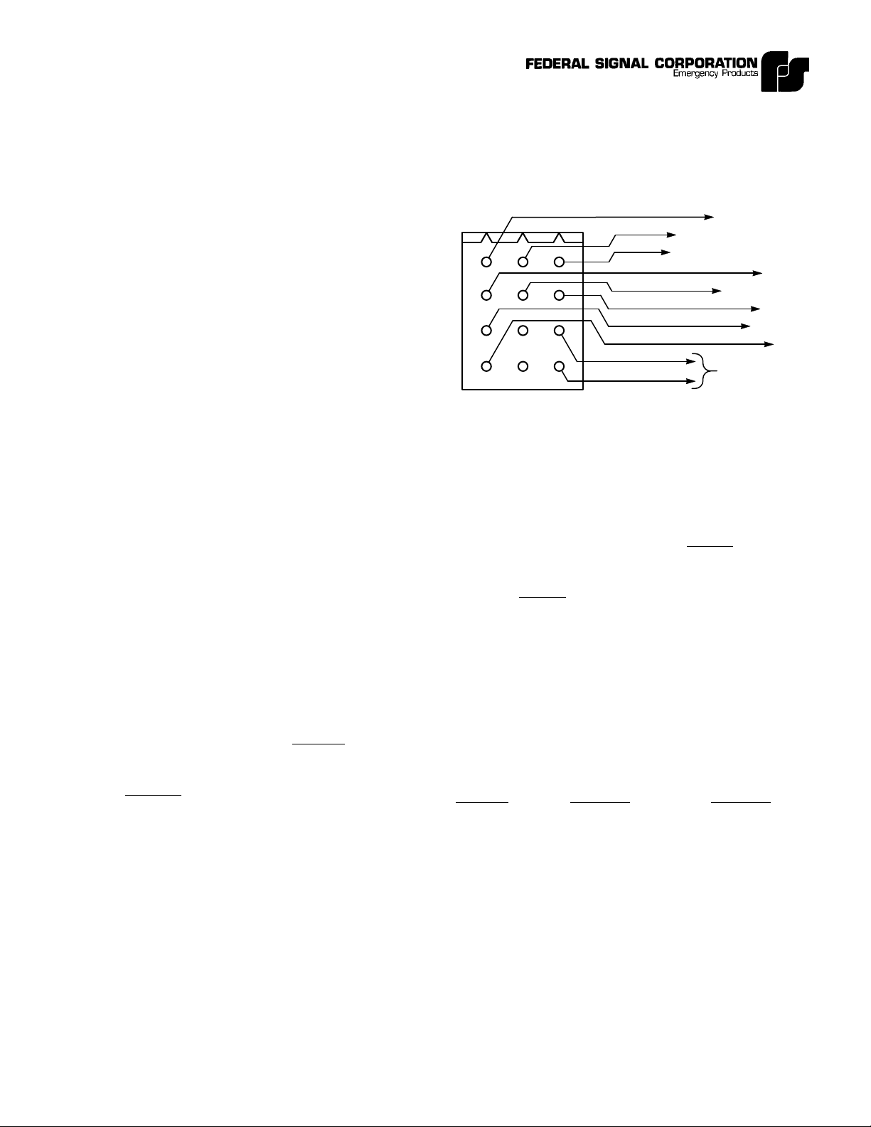
Control Cable Wiring Diagram.
Using 18 gauge wire, connect the speaker
leads (58W speakers to SPEAKER LO POWER and
100W speakers to SPEAKER HI POWER) as shown
in the Control Cable Wiring Diagram (new).
Operating Current (14.0Vdc-WAIL)
1 Low Power Speaker 5 amperes
2 Low Power Speakers 10 amperes
1 High Power Speaker 10 amperes
2 High Power Speakers 15 amperes
Voltage Output (approx.)
1 Low Power Speaker 45Vp-p
2 Low Power Speakers 40Vp-p
1 High Power Speaker 64Vp-p
2 High Power Speakers 60Vp-p
2. Page 4, paragraph 3-3.A. Speaker. Change
to read:
A. Speaker.
The unit is designed to operate with one 11ohm impedance speaker or two 11-ohm impedance
low power (58W) or high power (100W) speakers,
connected in parallel and in phase. On FEDERAL
speakers, this can be accomplished by connecting the
two speaker leads marked “1” to the SPEAKER
COMMON control cable lead and the two speaker
leads marked “2” to the SPEAKER HI POWER or
SPEAKER LO POWER control cable leads See the
Control Cable Wiring Diagram (new).
3. Page 7, Paragraph 4-3.E. HI-LO. Change to
read:
E. HI-LO.
This function is not available on the Model
PA300-012-NYSB.
4. Page 8, Paragraph 4-6. PRESS AND HOLD
FUNCTIONS. Change to read:
PRESS AND HOLD FUNCTIONS
Selector Press on Release of
Switch Horn Ring Horn Ring
Position Produces Produces
Manual Peak-and- Coast down
Hold and silence
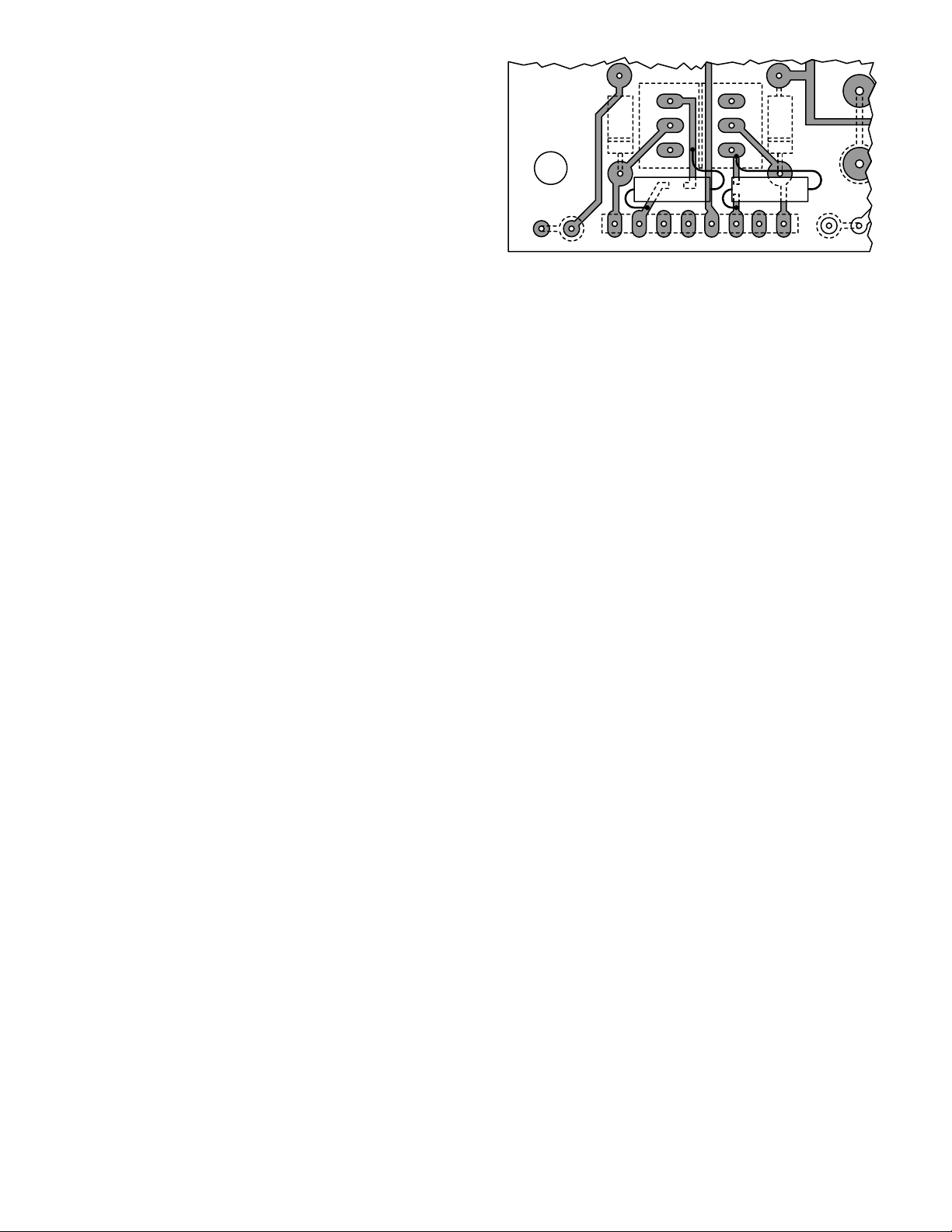
5. Page 14. Refer to the component location
diagram detail in this supplement to locate the
additional PA300-012-NYSB components (R59, R60).
6. Page 15. A Model PA300-012-NYSB schematic diagram is included in this supplement sheet.
Page 2
7. Page 16. Change the parts list as follows:
a. Add:R59, 60- Resistor, 0.47 ohm, 2W,
10%. Part No. 130A130.
b. Change the Part No. of T2 to
120C165A-04.
c. Change the Part No. of the Circuit
Board (with parts installed) to 200C860-03.
NOTE:
SOLDER SIDE
OF P.C. BOARD
IS SHOWN
R51
Q5 Q6
E
C
CR14
B
R60 R59
8
7654321
B
C
E
Component Location Detail.
CR13
J4
R54
R48
290A3860
-2-
Page 3

Model PA300-012-NYSB Schematic Diagram.
 Loading...