

Federal Signal Corporation MAC-02, MAC-01 Description, Specifications, And Operations Manual
Page 1
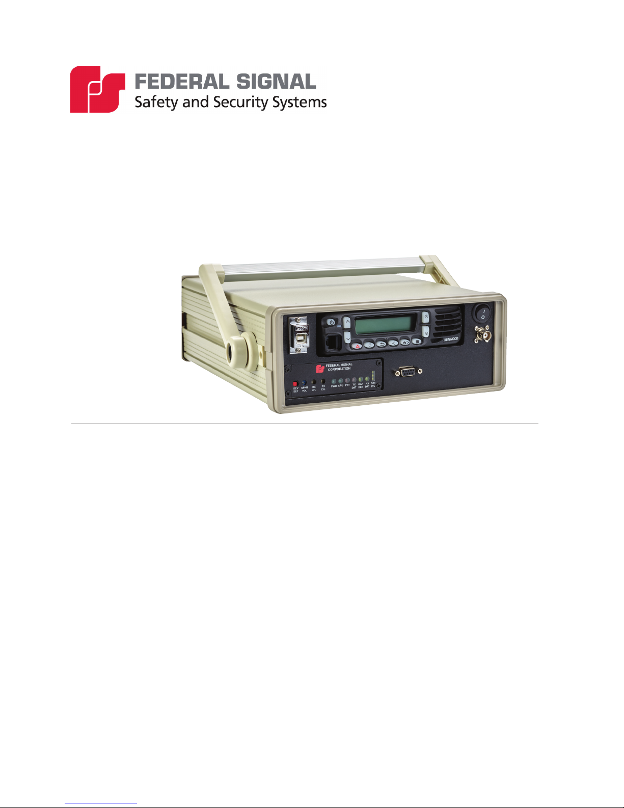
Mobile Activation Case
Models MAC-01 and MAC-02
Description, Specications,
and Operations Manual
25500128
Rev. A1 0817
Printed in U.S.A.
© Copyright 2017 Federal Signal Corporation
Page 2

Limited Warranty
This product is subject to and covered by a limited warranty,
a copy of which can be found at www.fedsig.com/SSG-Warranty.
A copy of this limited warranty can also be obtained by written
request to Federal Signal Corporation, 2645 Federal Signal Drive,
University Park, IL 60484, email to info@fedsig.com or
call +1 708-534-3400.
This limited warranty is in lieu of all other warranties, express or
implied, contractual or statutory, including, but not limited to the
warranty of merchantability, warranty of tness for a particular
purpose and any warranty against failure of its essential purpose.
2645 Federal Signal Drive
University Park, Illinois 60484-3617
www.fedsig.com
Customer Support 800-548-7229 • +1 708 534-3400
Technical Support 800-524-3021 • +1 708 534-3400
Kenwood NX-700/NX-800 radios are a registered trademark of JVC KENWOOD Corporation.
Pelican products are registered and/or unregistered trademarks of Pelican Products, Inc., its subsidiaries and/or afliates.
All products indicated are trademarks of Federal Signal Corporation.
All other product names or trademarks are properties of their respective owners.
Page 3

Contents
Safety Messages......................................................................................................................................................4
General Description ................................................................................................................................................6
Introduction .........................................................................................................................................................6
Features .............................................................................................................................................................. 6
Customer-Supplied Accessory .................................................................................................................... 6
Input/Output Denitions .........................................................................................................................................7
Unpacking the Kit ................................................................................................................................................ 8
Specications ..........................................................................................................................................................9
Operating Instructions .......................................................................................................................................... 10
Setting up the MAC for use ............................................................................................................................... 10
Activating Sirens Using Commander Software ................................................................................................. 11
Powering the MAC ............................................................................................................................................ 11
Testing the MAC ................................................................................................................................................12
Getting Service ......................................................................................................................................................12
Figures
Figure 1 Front of MAC Radio Case ........................................................................................................................7
Figure 2 Back of MAC Radio Case ......................................................................................................................... 7
Figure 3 Backpack ................................................................................................................................................... 7
Figure 4 Picture of MAC Contents .........................................................................................................................8
Figure 5 MAC Block Diagram ...............................................................................................................................10
Figure 6 USB cable between computer and MAC Radio Case .......................................................................... 11
Figure 7 Automotive Accessory Power Cable .................................................................................................... 12
Figure 8 Automotive Accessory Power Cable switch ........................................................................................ 12
Tables
Table 1 MAC Contents ............................................................................................................................................. 8
Table 2 Electrical ..................................................................................................................................................... 9
Table 3 Environmental ............................................................................................................................................ 9
Table 4 Physical ....................................................................................................................................................... 9
Description, Specications, and Operations Manual
3
Page 4

Safety Messages
Safety Messages
It is important to follow all instructions shipped with this product.
Listed below are important safety instructions and precautions you should follow:
Important Notice
Federal Signal reserves the right to make changes to devices and specications detailed in
the manual at any time in order to improve reliability, function or design. The information
in this manual has been carefully checked and is believed to be accurate; however, no
responsibility is assumed for any inaccuracies.
Publications
Federal Signal recommends the following publications from the Federal Emergency
Management Agency for assistance with planning an outdoor warning system:
• The “Outdoor Warning Guide” (CPG 1-17)
• “Civil Preparedness, Principles of Warning” (CPG 1-14)
• FEMA-REP-1, Appendix 3 (Nuclear Plant Guideline)
• FEMA-REP-10 (Nuclear Plant Guideline).
Planning
• If sirens are not activated in a timely manner when an emergency condition
exists, they cannot provide the intended audible warning. It is imperative that
knowledgeable people, who are provided with the necessary information, are
available at all times to authorize the activation of the sirens.
• When sirens are used out of doors, people indoors may not be able to hear the
warning signals. Separate warning devices or procedures may be needed to
effectively warn people indoors.
• The sound output of sirens is capable of causing permanent hearing damage. To
prevent excessive exposure, carefully plan siren placement, post warnings, and
restrict access to areas near sirens.
• Activating the sirens may not result in people taking the desired actions if those to
be warned are not properly trained about the meaning of siren sounds. Siren users
should follow FEMA recommendations and instruct those to be warned of correct
actions to be taken.
• After installation, service, or maintenance, test the siren system to conrm
that it is operating properly. Test the system regularly to conrm that it will be
operational in an emergency.
4
Mobile Activation Case (Models MAC-01 and MAC-02)
Page 5

Safety Messages
• If future service and operating personnel do not have these instructions to refer
to, the siren system may not provide the intended audible warning and service
personnel may be exposed to death, permanent hearing loss, or other bodily
injury. File these instructions in a safe place and refer to them periodically. Give a
copy of these instructions to new recruits and trainees. Also give a copy to anyone
who is going to service or repair the siren.
Installation and Service
• Sirens may be operated from remote control points. Whenever possible,
disconnect all siren power including batteries before working near the siren.
• After installation or service, test the siren system to conrm that it is operating
properly. Test the system regularly to conrm that it will be operational in an
emergency.
• If future service personnel do not have these warnings and all other instructions
shipped with the equipment to refer to, the siren system may not provide the
intended audible warning and service personnel may be exposed to death,
permanent hearing loss, or other bodily injury. File these instructions in a safe
place and refer to them periodically. Give a copy of these instructions to new
recruits and trainees. Also, give a copy to anyone who is going to service or repair
the sirens.
• To reduce the risk of electric shock, do not perform any servicing other than what
is contained in the operating instructions unless you are qualied to do so. Refer
all servicing to qualied service personnel. Always test the MAC before using
after repairs have been made.
Operation
Failure to understand the capabilities and limitations of your siren system could result in
permanent hearing loss, other serious injuries or death to persons too close to the sirens
when you activate them or to those you need to warn. Carefully read and thoroughly
understand all safety notices in this manual and all operations-related items in all
instruction manuals shipped with equipment. Thoroughly discuss all contingency plans
with those responsible for warning people in your community, company, or jurisdiction.
Symbol Denition
_A _V
Pay careful attention to the notice located on the equipment.
Read and understand the information contained in this manual before
attempting to install or service the Informer.
Indicates to reduce the risk of re, replace fuse as marked.
Description, Specications, and Operations Manual
5
Page 6

General Description
General Description
Introduction
The Mobile Activation Case (MAC) is a portable radio activation system. This mobile
system allows you to activate your outdoor warning system using radio controls. The
MAC comes in two version: the MAC-01 supports VHF radio networks, and the
MAC-02 supports UHF radio networks. The MAC is a portable, self-contained radio
transceiver and Modem MSK with power and battery backup.
The following main components are required for mobile use:
• MAC includes backpack for storage and cables for connecting to user-supplied
laptop.
• Laptop computer equipped with Federal Signal Commander Software.
Set up these components in the eld and you are able to activate your warning system
through your laptop computer using Commander Software. The MAC comes with
a water-resistant backpack that includes everything you need to set up your mobile
workstation.
Features
The MAC has the following features.
• 30 Watt radio transceiver installed.
• Federal Signal Modem-MSK universal transceiver.
• USB port and backup RS232 port for connecting to your laptop.
• USB and RS232 serial cables.
• Bulkhead mounted female BNC antenna receptacle.
• Rubber duck antenna.
• Long-lasting rechargeable Li-ion battery with built-in battery charger.
• 8 hour standby operation followed by one hour continuous radio polling operation
without AC power, with radio at 10 Watts.
• 10 foot male-male fused automotive accessory power cable to interface 12 Vdc
automotive accessory power receptacle.
• AC power receptacle to charge internal battery with removable AC power cable.
• Padded water-resistant backpack to store and carry MAC and laptop computer.
Customer-Supplied Accessory
• Laptop computer (with power cord, if required) equipped with Federal Signal
Commander Software.
6
Mobile Activation Case (Models MAC-01 and MAC-02)
Page 7

Input/Output Denitions
Figure 1 Front of MAC Radio Case
USB Port
Modem-MSK
Figure 2 Back of MAC Radio Case
Input/Output Denitions
NX-700/NX-800 Radio
On/Off switch
BNC Antenna
RS232 port
Figure 3 Backpack
120 VAC charge input
12 Vdc automotive
receptacle
Description, Specications, and Operations Manual
7
Page 8

Input/Output Denitions
Unpacking the Kit
Ensure that the parts listed are included in the package. If you are missing any parts,
contact Customer Support. See Getting Service.
Table 1 MAC Contents
Description Part Number
Minimum Shift Keying (MSK) Modem* MODEM-MSK
12.8 Vdc LiFePO4 Battery Charger* 12000529-TERM
12.8 Vdc, 5 Ah, LiFePO4 Battery* 15500483
Kenwood NX-700 Radio* 19900172A
Right Angle, High, Antenna 240190B-02
6 Ft AC Power Cord 1461212A
Male to Male Cig. Lighter Cable 17500537
RS232, DB9(F) to DB9 Cable 1751190A
USB Type A/Type B Cable 1751410A
MAC Instruction Manual 25500128
Pelican Backpack #S115 864200177
*Included in the Mobile Activation Case enclosure.
Figure 4 Picture of MAC Contents
Mobile Activation Case (Models MAC-01 and MAC-02)
8
Page 9

Specications
Table 2 Electrical
AC Power Input 6 foot 3 conductor wire AC power cable
DC Power Input 12 Vdc female automotive accessory receptacle with 10 foot
Antenna Jack Panel mount female BNC
Antenna Rubber duck*
Battery 12.8 Volt 5 Ah Li-ion rechargeable
Charger 14.6 Volt, 1.5 A CC/CV
Radio Kenwood NX-700 for MAC-01, supports VHF radio networks
Modem MSK Modem radio interface
* If you require more radio frequency (RF) coverage, other antenna options are available
for purchase.
Specications
120 Vac for battery charger
fused male to male automotive DC power cable
NOTE: Does not charge battery.
Kenwood NX-800 for MAC-02, supports UHF radio networks
30 Watt (Set power per customer specications and FCC license)
Table 3 Environmental
Operating Temperature -30°C to +65°C
Humidity 0-95% Non-Condensing
Table 4 Physical
MAC Radio Case Size
(H x W x D)
Backpack Exterior
(H x W x D)
Backpack Interior
(H x W x D)
for laptop computer compartment
12.50 lb (5.67 kg)
4 in x 10 in x 13 in
18.50 in x 13 in x 10 in
15.5 in x 10.5 in x 1.1 in
Description, Specications, and Operations Manual
9
Page 10

Operating Instructions
Figure 5 MAC Block Diagram
Operating Instructions
The operating instructions consist of three parts:
• Setting up the MAC for use
• Activating sirens using Commander Software
• Powering the MAC
Setting up the MAC for use
To set up the MAC for use, do the following:
1. Connect antenna to BNC antenna port located on the front of the MAC Radio
Case.
NOTE: RF communications are affected by a number of physical factors; such
as, antenna placement and RF interference. Therefore, the placement of the radio
antenna on high ground typically improves radio commutations. Whereas, the
placement of the radio antenna inside a vehicle can degrade radio commutations.
2. Connect the USB cable between the computer and the USB port located in the
front the MAC Radio Case.
NOTE: You can use the RS232 port instead of the USB port.
10
Mobile Activation Case (Models MAC-01 and MAC-02)
Page 11

Operating Instructions
Figure 6 USB cable between computer and MAC Radio Case
Modem-MSK is on
3. Turn on the power switch located on the front of the MAC Radio Case. Ensure
that the radio and Modem-MSK power lights are on.
4. Use Commander Software to activate, monitor, and control remote devices (such
as, sirens).
Activating Sirens Using Commander Software
Commander Software allows you to activate your sirens. After you activate your siren
system, Commander Software performs a Poll and logs the results. A Poll will poll each
siren site for status.
NOTE: The operator must always be aware that site conditions shown on any
Commander System screen, including the map, are not in real time, but represent
conditions at the time of the last polling. Large systems may take several minutes to
complete a polling sequence.
Commander Software allows single point and click activation and polling.
See the Commander Software Reference Manual, located within the Commander
Software, for further software operation details.
Powering the MAC
If the MAC is not charged, you can power it by using your power receptacle in the
vehicle.
To power the MAC from the vehicle, do the following:
1. Connect the Automotive Accessory Power Cable to the plug located on the back
of the MAC Radio Case and the other side to an Automotive Accessory Power
receptacle in vehicle.
NOTE: This does not charge the MAC internal battery.
Description, Specications, and Operations Manual
11
Page 12

Getting Service
Figure 7 Automotive Accessory Power Cable
2. Turn on the Automotive Accessory Power Cable switch to the on position. The
Figure 8 Automotive Accessory Power Cable switch
LED is lit when plugged into an Automotive Accessory Power receptacle in
vehicle.
Testing the MAC
Refer to the MSK Modem Product Manual for further information. Verify RF settings and
test communications with all system components before placing into service.
Getting Service
If you are experiencing any difculties, contact Federal Signal Customer Care at:
800-548-7229 or 708-534-3400 extension 7511 or Technical Support at: 800-524-3021
or 708-534-3400 extension 7329 or through e-mail at: techsupport@fedsig.com. For
instruction manuals and information on related products, visit: http://www.fedsig.com/
12
Mobile Activation Case (Models MAC-01 and MAC-02)
 Loading...