

Federal Signal Corporation Latitude SignalMaster SL6S, Latitude SignalMaster SL8S Installation Instructions Manual
Page 1

Installation Instructions for Latitude
™
SignalMaster™ Models SL6S and SL8S
25500085 Rev. B2 1019
Safety Message to Installers and Operators of Emergency Vehicle Safety Equipment
People's lives depend on your proper installation and servicing of Federal Signal products. It is important
to read and follow all instructions shipped with this product. Listed below are some other important safety
instructions and precautions you should follow:
Before Installation or Service
Qualications
• To properly install or service this equipment, you must have a good understanding of automotive
electrical procedures and systems along with proficiency in the installation and service of safety warning
equipment. Always refer to the vehicle service manuals when installing equipment on a vehicle.
Electrical Hazards
• Never attempt to install aftermarket equipment that connects to the vehicle wiring without reviewing a
vehicle wiring diagram available from the vehicle manufacturer. Ensure that your installation will not aect
vehicle operation and safety functions or circuits.
During Installation or Service
• To avoid a battery explosion, always disconnect the negative battery cable first and reconnect it last.
Avoid a spark when connecting near or to the battery. The gasses produced by a battery can cause a
battery explosion that could result in vehicle damage and serious injury.
• For the light to function properly, a separate ground connection must be made. If practical, it should be
connected to the negative battery terminal. At a minimum, it may be attached to a solid metal body or
chassis part that provides an eective ground path.
• Do not install equipment or route wiring or a plug-in cord in the deployment path of an airbag.
• When drilling into a vehicle structure, be sure that both sides of the surface are clear of anything
that could be damaged. Remove all burrs from drilled holes to prevent electrical shorts, grommet all
drilled holes through which wiring passes. Also ensure that mounting screws do not cause electrical or
mechanical damage to the vehicle.
• Locate the light control so the VEHICLE and CONTROL can be operated safely under all driving
conditions.
• This product contains high intensity LED devices. To prevent eye damage, DO NOT stare into the light
beam at close range.
After Installation or Service
• If a vehicle seat is temporarily removed, verify with vehicle manufacturer if the seat needs to be
recalibrated for proper airbag deployment.
• To ensure proper operation, test all vehicle functions, including horn operation, vehicle safety functions,
and vehicle light systems. Ensure that installation has not aected vehicle operation or changed any
vehicle safety function or circuit.
• After installation, test the lights to ensure that they are operating properly.
Page 2

Installing the Latitude™SignalMaster™ Models SL6S and SL8S
• After installation and testing are complete, provide a copy of these instructions to instructional sta and all
operating personnel.
• File these instructions in a safe place and refer to them when maintaining and/or reinstalling the product.
During Operation
• This product contains high intensity LED devices. To prevent eye damage, DO NOT stare into the light
beam at close range.
• Do not attempt to activate or deactivate the light control while driving in a hazardous situation.
• Frequently inspect the light to ensure that it is operating properly and that it is securely attached to the
vehicle.
• These lights are intended as a secondary warning system only. They are not intended for use as a primary
warning system.
Failure to follow all safety precautions and instructions may result in property damage, serious injury, or death.
Introduction
The Latitude SM is an addition to Federal Signal’s family of SignalMaster directional lights. Equipped with
three LEDs per position and Federal Signal’s Solaris® LED reflectors, the Latitude SM delivers an impressive
optical performance for your vehicle. Meeting Class 1 specifications and available for both interior and exterior
mounting, the Latitude SM is suitable for many vehicle applications.
This directional light is available in six-head and eight-head versions. These models come equipped with the
Federal Signal economy SignalMaster control that allows users to easily install and operate built-in directional
signals of left, right, and center-out.
In addition to the three built-in directional signals, an additional warning mode can be activated by applying
+12 Vdc simultaneously to the Red, White, and Green wires and -GND to the Black wire. A 75 FPM pattern is
the only available pattern. To activate the mode, an additional, installer supplied, switch required. This mode
has the highest priority. When not in flashing mode and power is on the red wire, applying power to the green
or white wire gives the corresponding left or right arrow priority over the center out mode.
Unpacking the Product
After unpacking the product, inspect it for damage that may have occurred in transit. If it has been damaged,
do not attempt to install or operate it. File a claim immediately with the carrier, stating the extent of damage.
Failure to identify damage before installation could lead to rejection of any claim. Carefully check all
envelopes, shipping labels, and tags before removing or destroying them. Ensure that the parts listed in
Table1 are included in the package. If you are missing any parts, contact Federal Signal Customer Support at
1-800-264-3578, 7 a.m. to 5 p.m., Monday through Friday (CT).
Table 1 Product Specications
6-Head (24 inches) 8-Head (32 inches) 8-head (48 inches)
Voltage 12.8 Vdc 12.8 Vdc 12.8 Vdc
Amp Draw (Total) 3 A 4 A 4 A
Operating Temp. -22°F to +149°F
(-30°C to +65°C)
Dimensions (H x L x D) 1.13 x 24.2 x 2.63 inches
(2.86 x 61.5 x 6.67 cm)
Shipping Weight 3.8 lb (1.7 kg) 4.0 lb (1.8 kg) 4.3 lb (9.48 kg)
-22°F to +149°F
(-30°C to +65°C)
1.13 x 31.8 x 2.63 inches
(2.86 x 80.5 x 6.67 cm)
-22°F to +149°F
(-30°C to +65°C)
1.13 x 48.0 x 2.63 inches
(2.86 x 121.92 x 6.67 cm)
2
Latitude™ and SignalMaster™ Models SL6S and SL8S
Federal Signal www.fedsig.com
Page 3
Installing the Latitude™ SignalMaster™ Models SL6S and SL8S
Mounting the Light Bar
AIRBAG DEPLOYMENT: Do not install equipment or route wiring in the deployment path of an airbag.
Failure to observe this warning will reduce the effectiveness of the airbag or potentially dislodge the
equipment, causing serious injury or death.
LIGHT OUTPUT COMPLIANCE: This product is intended for supplemental warning and for use in
conjunction with an approved primary warning light system. Consult local codes and regulations to
determine if the power supply / light head combination complies with the horizontal or vertical mount
position desired in your application. Failure to follow this caution could result in reduced light output
and reduced warning system effectiveness.
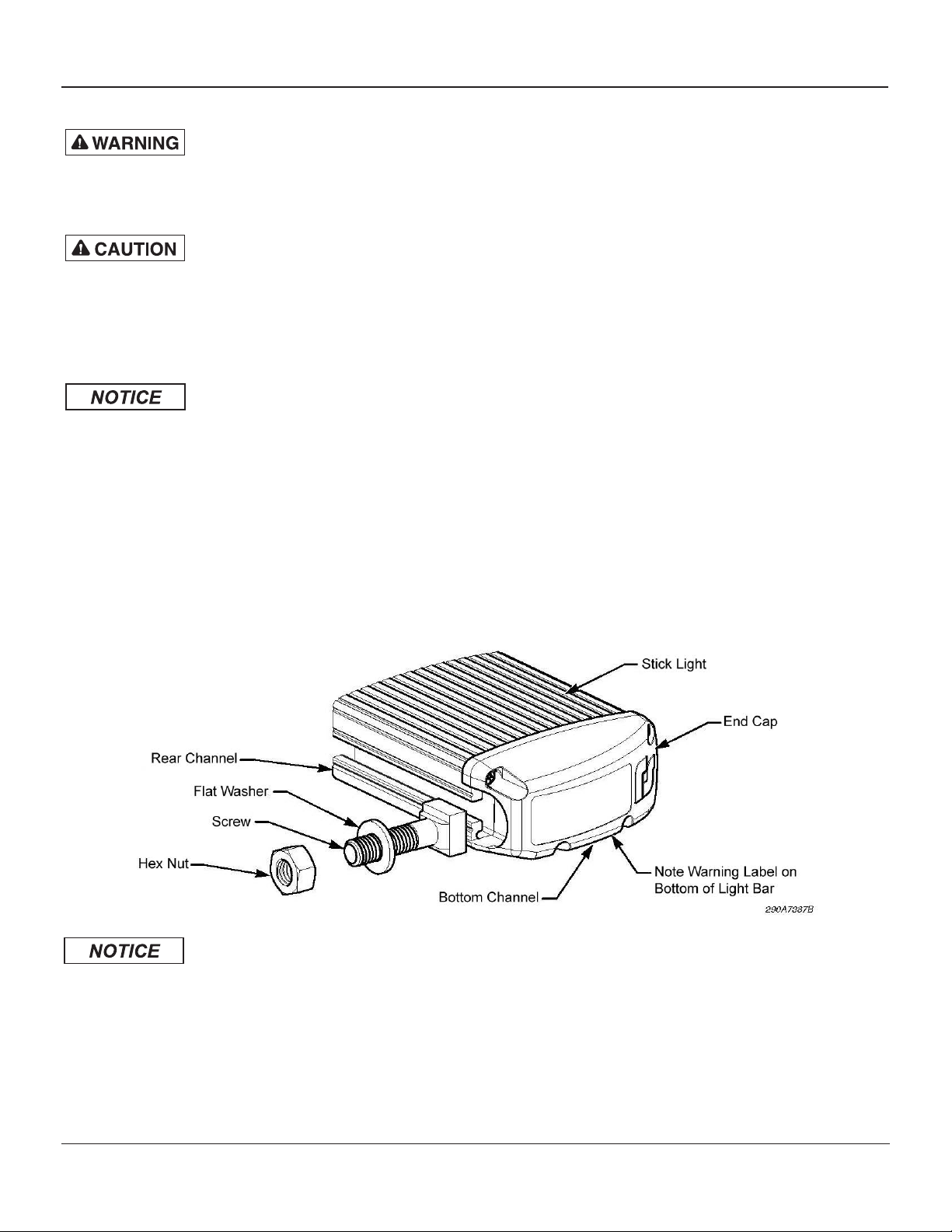
WATER DAMAGE PRECAUTION: When installing the Latitude on the exterior of a vehicle, ensure that
it is mounted with the bottom channel facing down (Figure 1). Failure to follow this precaution may
cause water to enter the light bar and damage the circuitry.
To mount the light bar:
1. Determine which side of the light bar to secure to the mounting surface. From a horizontal orientation, the
bottom and rear surfaces of the light bar are available for mounting.
2. Locate the opening in the selected mounting-bolt channel and drop in four mounting screws. See Figure 1.
Figure 1 Light bar positioned horizontally with mounting hardware
DRILLING PRECAUTIONS: When drilling holes, check the area you are drilling into to ensure that you
do not damage vehicle components while drilling. All drilled holes should be de-burred, and all sharp
edges should be smoothed. All wire routings going through drilled holes should be protected by a
grommet or convolute/split loom tubing.
3. Drill holes as needed for the mounting screws.
4. Secure the light bar to the mounting surface using the supplied nuts.
Latitude™ and SignalMaster™ Models SL6S and SL8S
Federal Signal www.fedsig.com
3
Page 4

Installing the Latitude™SignalMaster™ Models SL6S and SL8S
Mounting the Control Head
NOTE: When selecting a mounting location for the control head, keep the cable length of the SignalMaster in
mind. Plan wiring and cable routing before installation.
To mount the control head:
1. Assemble the control head as shown in Figure 2. For proper operation of the unit, the switches must be
installed as shown.
2. Select a mounting location for the control head that allows the vehicle and controls to be operated safely
at all times.
3. Use the control head as a template and scribe two drill position marks at the selected mounting location.
4. Drill two holes at the scribed position marks.
5. Secure the control head to the mounting surface with two user-supplied sheet-metal screws.
Figure 2 Electrical connections for control head
Wiring Power Connections to the Control Head
WIRING PRECAUTION: When installing a split SignalMaster system, ensure that the assembly on the
left rear side of the vehicle only signals left. Do not connect the white wire to the left rear-mounted
SignalMaster. The split SignalMaster on the right should only signal right. Do not connect the green
wire to the right rear-mounted SignalMaster. Failure to heed this warning may cause a vehicle
accident, resulting in serious injury or death.
HIGH CURRENT ARCING: Do not connect this system to the vehicle battery until ALL other electrical
connections are made, mounting of all components is nished, and you have veried that no shorts
exist. High current conductors can cause hazardous sparks or burning wire, resulting in electrical
res.
4
Latitude™ and SignalMaster™ Models SL6S and SL8S
Federal Signal www.fedsig.com
Page 5

Installing the Latitude™ SignalMaster™ Models SL6S and SL8S
BURN HAZARD: After prolonged operation, the Latitude dissipates heat and can cause burns. Do not
hold it in your hands for extended periods of time. Do not touch it during, or shortly after, operation.
Always allow the stick light to cool before handling.
To wire the control head to power:
1. Route installer-supplied red and black 18 AWG (minimum) wires to the power source. Ensure that the power
source is capable of supplying an additional 10 amperes.
2. Connect the black wire to a known good chassis ground. This connection must be capable of supplying
10amperes. Do not connect the red wire to the positive (+) power source terminal at this time.
3. Wrap the control cable’s stripped wire ends with tape and route the cable to the mounting location of the
control head.
4. Crimp four 1/4-inch straight-terminals on the ends of the cable wires and the jumper wire combination. See
Figure 3.
5. Connect the terminals on the switch as shown in Figure 3.
Figure 3 Terminal connections from the control head
Wiring the Illuminated ON/OFF Switch on the Control Head
HIGH CURRENT ARCING: Do not connect this system to the vehicle battery until ALL other electrical
connections are made, mounting of all components is nished, and you have veried that no shorts
exist. High current conductors can cause hazardous sparks or burning wire, resulting in electrical
res.
PCB DAMAGE/IMPROPER WIRING: Improper wiring of the illuminated switch feature will result in
printed circuit board damage. Ensure that the chassis ground lead is connected to the gold (pin 3)
terminal and that the unterminated end of the lead is connected to a known good chassis ground.
To wire the illuminated ON/OFF switch:
1. Connect the right-angle terminal on the ground lead of the switch bracket to the gold terminal (Pin 3) of the
ON/OFF switch. See Figure 3.
Latitude™ and SignalMaster™ Models SL6S and SL8S
Federal Signal www.fedsig.com
5
Page 6

Installing the Latitude™SignalMaster™ Models SL6S and SL8S
2. Route the unterminated end of the ground lead to a known good chassis ground.
3. Cut the lead to length and crimp the supplied ring terminal on the lead. If necessary, additional 18 AWG
wire may be spliced to the ground lead.
4. Secure the lead to the chassis ground with a user-supplied screw.
Inspection and Final Installation
To complete and verify that the light bar and control head work properly:
1. Ensure that there are no loose wire strands or other bare wires that may cause a short circuit. All wires
must be protected from any sharp edges that could eventually cut through the insulation.
2. Connect the 18 AWG red wire to the (+) positive terminal of the battery using an in-line, user-supplied
10A fuse and fuseholder. To protect the entire length of the wire, locate the fuse as near to the battery as
possible.
NOTE: If the leads of the power supply are reversed, all directional lamps will light simultaneously. Correct
the wiring before proceeding.
3. Read and understand the operation instructions and test the lights for proper operation of all functions.
6
Latitude™ and SignalMaster™ Models SL6S and SL8S
Federal Signal www.fedsig.com
Page 7

Installing the Latitude™ SignalMaster™ Models SL6S and SL8S
Getting Technical Support
For technical support, please contact:
Federal Signal Corporation
Service Department
Phone: 1-800-433-9132
Fax: 1-800-343-9706
Email: empserviceinfo@fedsig.com
Getting Repair Service
The Federal Signal factory provides technical assistance with any problems that cannot be handled locally. Any
product returned to Federal Signal for service, inspection, or repair must be accompanied by a Return Material
Authorization (RMA). Obtain a RMA from a local Distributor or Manufacturer’s Representative. Provide a brief
explanation of the service requested, or the nature of the malfunction.
Address all communications and shipments to the following:
Federal Signal Corporation
Service Department
2645 Federal Signal Dr.
University Park, IL 60484-3167
Limited Warranty
This product is subject to and covered by a limited warranty, a copy of which can be found at www.fedsig.
com/SSG-Warranty. A copy of this limited warranty can also be obtained by written request to Federal Signal
Corporation, 2645 Federal Signal Drive, University Park, IL 60484, email to info@fedsig.com or call
+1 708-534-3400.
This limited warranty is in lieu of all other warranties, express or implied, contractual or statutory, including,
but not limited to the warranty of merchantability, warranty of fitness for a particular purpose and any warranty
against failure of its essential purpose.
Latitude™ and SignalMaster™ Models SL6S and SL8S
Federal Signal www.fedsig.com
7
Page 8

2645 Federal Signal Drive
University Park, Illinois 60484-3167
www.fedsig.com
Customer Support
Police/Fire-EMS: 800-264-3578•+1708534-3400
WorkTruck: 800-824-0254•+1708534-3400
TechnicalSupport: 800-433-9132•+1708534-3400
© Copyright 2013-2019 Federal Signal Corporation
 Loading...