

Federal Signal Corporation Informer I-HIOW, Informer I-UIOW Installation And Operation Manual
Page 1

Informer™ Wall Mount Series
Models I-HIOW and I-UIOW
Tone Alert Receiver
You must program the Informer with I-SW software version 3.6 or greater.
25500089
Rev. B1 1114
Printed in U.S.A.
© Copyright 2014 Federal Signal Corporation
Installation and
Operation Manual
Page 2

Limited Warranty
The Alerting and Notification Systems Division of Federal Signal Corporation (Federal)
warrants each new product to be free from defects in material and workmanship, under normal use
and service, for a period of two years on parts replacement and factory-performed labor (one year
for Informer, EAS, and Federal software products) from the date of delivery to the first userpurchaser. Federal warrants every 2001, Eclipse and 508 Siren (Top of pole only) to be free from
defects in material, per our standard warranty, under normal use and service for a period of five
years on parts replacement.
During this warranty period, the obligation of Federal is limited to repairing or replacing, as
Federal may elect, any part or parts of such product which after examination by Federal, are
determined to be defective in material and/or workmanship.
Federal will provide warranty for any unit, which is delivered, transported prepaid, to the Federal
factory or designated authorized warranty service center for examination and such examination
reveals a defect in material and/or workmanship.
This warranty does not cover travel expenses, the cost of specialized equipment for gaining access
to the product, or labor charges for removal and re-installation of the product. The Federal Signal
Corporation warranty shall not apply to components or accessories that have a separate warranty
by the original manufacturer, such as, but not limited to batteries.
Federal will provide on-site warranty service during the first 60-days after the completion of the
installation, when Federal has provided a turn-key installation including optimization and/or
commissioning services.
This warranty does not extend to any unit which has been subjected to abuse, misuse, improper
installation or which has been inadequately maintained, nor to units which have problems related
to service or modification at any facility other than the Federal factory or authorized warranty
service centers. Moreover, Federal shall have no liability with respect to defects arising in
Products through any cause other than ordinary use (such as, for example, accident, fire, lightning,
water damage, or other remaining acts of God).
THERE ARE NO OTHER WARRANTIES, EXPRESSED OR IMPLIED, INCLUDING BUT
NOT LIMITED TO, ANY IMPLIED WARRANTIES OF MERCHANTABILITY OR FITNESS
FOR A PARTICULAR PURPOSE. IN NO EVENT SHALL FEDERAL BE LIABLE FOR ANY
LOSS OF PROFITS OR ANY INDIRECT OR CONSEQUENTIAL DAMAGES ARISING OUT
OF ANY SUCH DEFECT IN MATERIAL WORKMANSHIP.
2645 Federal Signal Drive, University Park, IL 60484-3167
Phone: 708-534-3400
Website: http://www.alertnotification.com
Page 3

Informer Wall Mount Series
Contents
Safety Message ........................................................................................................................ 1
Read and Understand ............................................................................................................ 1
Installation Considerations ...................................................................................................... 1
Notices ................................ ................................................................ ................................... 2
Servicing ................................................................................................................................ 2
Symbol Definition ................................................................................................................ 2
General Description ................................................................................................................. 3
Introduction to the Informer TAR ............................................................................................. 3
Features ................................................................................................................................. 4
Optional Features ................................................................................................................... 4
Informer Wall Mount Main Components .................................................................................. 5
Input/Output Definitions .......................................................................................................... 6
Specifications........................................................................................................................... 7
Installation Instructions ..........................................................................................................10
Determine a Suitable Location ...............................................................................................10
Wall Mounting ........................................................................................................................11
Recessed Mounting ...............................................................................................................12
Input/Output Connections ......................................................................................................13
Wiring the Device ..................................................................................................................13
Operating Instructions ............................................................................................................16
General Information ...............................................................................................................16
Power Supply ........................................................................................................................16
LED Indicators .......................................................................................................................17
Keypad ..................................................................................................................................17
Adjusting the Volume .........................................................................................................17
Receiving an Alert Message ..................................................................................................18
Receiving a Test Message ....................................................................................................19
Tone-Alert Radio Failure .......................................................................................................19
Dual Relay and 600 ohm Audio Output..................................................................................19
Relay Outputs ....................................................................................................................19
600 Ohm Audio Output ......................................................................................................19
Monitoring Weather (NOAA Weather Radio and Channel Selection) .....................................20
Testing .....................................................................................................................................21
Training....................................................................................................................................21
Using the Battery Switch .......................................................................................................21
Page 4

Informer Wall Mount Series
Obtaining Service ...................................................................................................................22
Informer Wall Mount Service .................................................................................................22
Replacing the Battery ............................................................................................................ 22
Index ........................................................................................................................................23
Figures
Figure 1 Rear View – Hole Measurements ................................................................................................. 11
Figure 2 Side View – Hole Measurements .................................................................................................. 12
Figure 3 Internal Wiring for the Informer Wall Mount .................................................................................. 15
Figure 4 Informer Keypad ........................................................................................................................... 16
Tables
Table 1 Electrical ........................................................................................................................................... 7
Table 2 Bandwidth Receivers 25–30 kHZ ..................................................................................................... 7
Table 3 Bandwidth Receivers 12.5 kHz ........................................................................................................ 7
Table 4 Acoustic ............................................................................................................................................ 8
Table 5 Dual Relay and 600 Ohm Audio ...................................................................................................... 8
Table 6 Signaling Formats ............................................................................................................................ 8
Table 7 Environmental .................................................................................................................................. 9
Table 8 Physical ............................................................................................................................................ 9
Table 9 Audio/Relay Output – Input/Output Connections ........................................................................... 13
Table 10 LED Indicators .............................................................................................................................. 17
Table 11 Informer Buttons........................................................................................................................... 18
Page 5

Informer Wall Mount Series
1
Safety Message
Safety Message
It is important to follow all instructions shipped with this product. This
device is to be installed by trained personnel who are thoroughly
familiar with the country electric codes and will follow these guidelines
as well as local codes.
Listed below are important safety instructions and precautions you should follow:
Read and Understand
Read and understand all instructions before installing or operating this product.
Adhere to all warnings and operating instructions.
Proper installation, placement, and testing are required to ensure the unit is able
to perform as intended. Perform installation, placement, and testing after the
installer has read and understood this manual.
Installation Considerations
Do not use near water; for example, near a bathtub, washbowl, kitchen sink,
laundry tub, in a wet basement, or near a swimming pool, rain, or similar
environments.
Mount to a wall only as specified in this manual.
Place away from heat sources; such as, radiators, heat registers, stoves, or other
accessories that produce heat.
Do not exceed maximum accessory relay output rating of 30 VDC, 5 Amps.
Locate an outdoor antenna away from power lines.
If an outside antenna is connected to the receiver, make sure the antenna system
is grounded in order to provide protection against voltage surges and built up
static charges. Article 810 of the National Electrical Code, ANSI/NFPA 70,
provides information with regard to proper grounding of the mast and supporting
structure, grounding of the lead-in wire to the antenna-discharge unit, size of
grounding conductors, location of antenna discharge unit, connection to
grounding electrodes, and requirements for the grounding electrode.
Page 6

2
Informer Wall Mount Series
Safety Message
Notices
Take care so that objects do not fall and liquids are not spilled into the enclosure
through openings.
Keep the Informer at least six inches away from a listener’s ears whenever the
Informer Power LED is on or blinking. The sound output of the Informer may
cause hearing damage if the Informer is activated too close to the user.
Clean with a non-abrasive cleaner and a damp cloth. Do not apply solvents
directly onto the Informer.
Retain instructions for future reference.
Service the Informer by qualified service personnel when the following has
occurred to the Informer:
Objects haven fallen onto, or liquid has been spilled into
Does not appear to operate normally
Exhibits a marked change in performance
Exposed to rain
Has been dropped
Enclosure is damaged
Servicing
To reduce the risk of electric shock, do not perform any servicing other
than what is contained in the operating instructions unless you are
qualified to do so. Refer all servicing to qualified service personnel.
Always test the Informer before using after repairs have been made.
Symbol Definition
Indicates to reduce the risk of fire, replace fuse as marked.
Page 7

Informer Wall Mount Series
3
General Description
General Description
Introduction to the Informer TAR
The Informer Wall Mount Tone Alert Receiver (TAR) is an emergency alerting
device available in VHF and UHF bands from 150-170 MHz and 450-470 MHz. It is
also capable of decoding multiple formats (such as, single-tone, two-tone, DTMF and
optionally EAS or Federal Digital) at the same time. These features enable the
Informer to be easily integrated into virtually any new or existing warning system.
The Informer is a robust radio receiver with a loud speaker output designed
specifically for warning applications. You can mount the unit on the wall or recess it
in the wall. The Informer comes with an antenna to mount on the front of the unit or
in another location, such as outside, by using the internal BNC connector and using
the punchouts for access into the unit. The Informer has a built-in battery and charger
to provide reliable operation even in the event of an AC power failure. The optional
LP1 strobe is powered through the internal transformer, which requires AC power.
You can program the Informer with up to four separate warning tones plus a channel
monitor function for live public address (PA) announcements. Two programmable
relay outputs and a 600 Ohm audio output are also available. You can use these
outputs to control other equipment; such as, pre-wired LP1 strobe light for warning
the hearing impaired and to tie into external PA systems respectively.
You may program up to four separate RF channels into the Informer. The channels
are easily selected from the built in membrane keypad. Each of the RF frequencies
must be within the allowable frequency spread for the RF band being used. Refer to
the “Specification” section on page 7.
The Informer is completely programmable through a built-in RS232 serial port from
an easy to use Windows XP/Vista/7® based software program. All data is stored in
non-volatile memory. You can update application software and user specific
configuration data through the serial port.
The Informer series receivers meet all requirements defined by the Federal
Emergency Management Agency (FEMA) for the CSEPP programs.
Page 8

4
Informer Wall Mount Series
General Description
Features
Available in two (2) frequencies bands: VHF 150-170 MHz and UHF
450-470 MHz
Long life rechargeable battery with built-in charger (Only units built after May
2015 are equipped with a battery.)
Wide temperature operating range
Excellent RF sensitivity and selectivity
Fully programmable RF—no tuning required
Clean, low distortion of recovered audio
Loud +80 dBA output at 10 feet
Signal to Noise based squelch circuit, does not open receiver in high radio noise
environments; that is, near computers, etc.
Programmable for wide or narrow band
Programmable RF, Single Tone, Two-Tone, DTMF, CTCSS, and CDCSS (DPL)
decoding
Re-programmable over RS232 port
Volume control, Monitor, and Reset buttons with diagnostic LEDs
Optional Features
Programmable MSK decoder compatible with the Federal’s Commander
Software.
Programmable EAS decoder for decoding NOAA radio SAME code alerts.
600 Ohm audio output and two (2) SPDT relay outputs.
Windows XP/Vista/7® based programming software.
Ability to top mount Model LP1-012 12 V mini-strobe when used in Wall Mount
configuration. Strobe does not function during battery backup mode.
NOTE: The MSK and EAS decoders are not available simultaneously in the same
unit. You can use all other options together.
Page 9
Informer Wall Mount Series
5
General Description
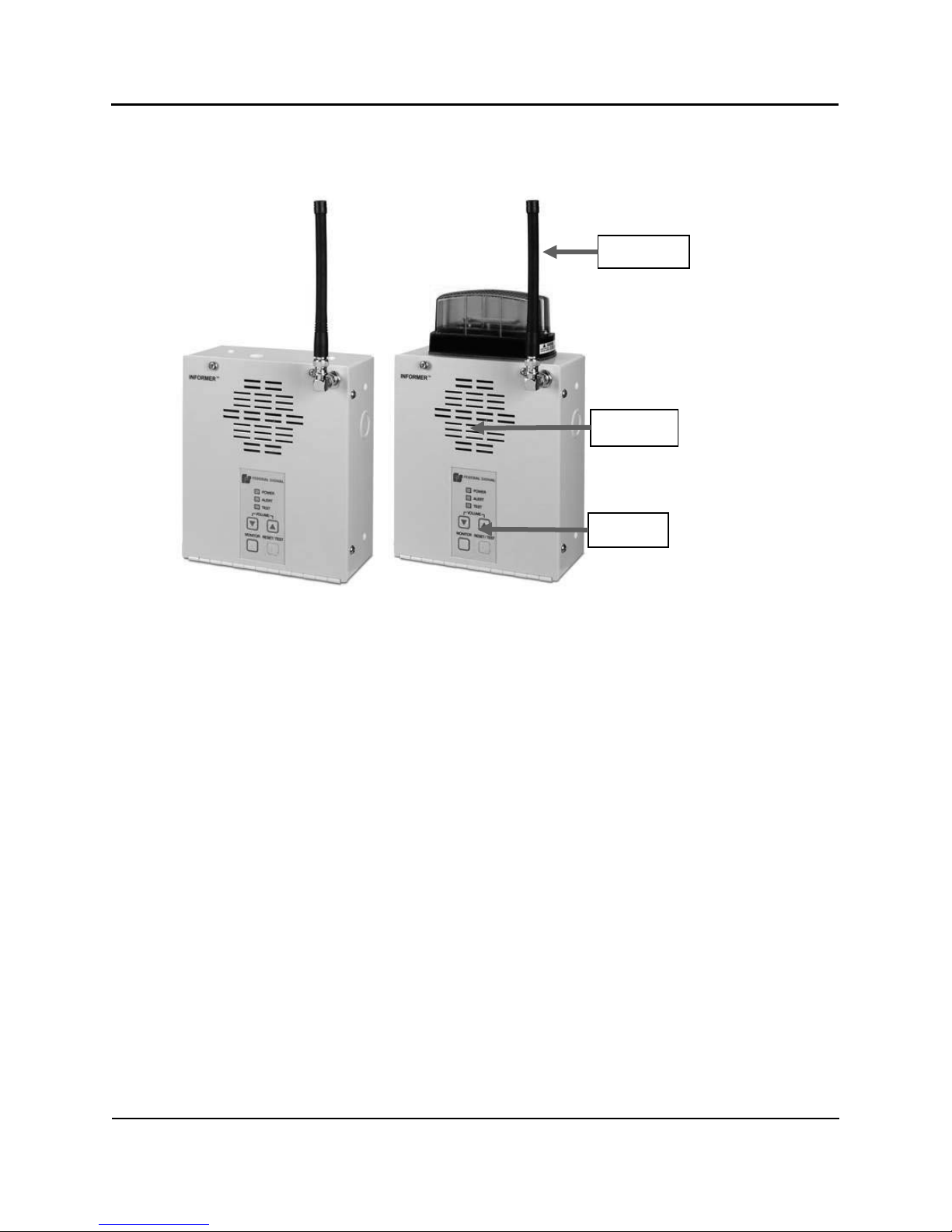
Speaker
Keypad
Antenna
Informer Wall Mount Main Components
Page 10

6
Informer Wall Mount Series
General Description
600 Ohm Audio/Relay Outputs
BNC Antenna Connector
6 V Battery
Audio Output Level Adjustment
Squelch
Programming Port
Battery Switch
OFF ON
Input/Output Definitions
Page 11

Informer Wall Mount Series
7
Specifications
Antenna Impedance
50 Ohms
Antenna Type
Rubber duck with swivel BNC connector
Sensitivity – 12 dB
SINAD
.35 for 12 dB SINAD per EIA-603, part 4.1.4
Input
115 to 230 VAC
Operating Current
<350 mA. Max.
Battery Capacity
Internal sealed lead-acid, capable of running for six (6)
hours in standby mode with fifteen (15) minutes of each
hour generating siren beep audio at rated audio output.
(Based on Pulsed Tone audio.) Low voltage cutoff set to
5.38 VDC +/- 0.1 VDC.
Hum and Noise
-37 dB when unsquelched,
-57 dB squelched relative to full quieting signal with
1 kHz tone at 60% rated system deviation at rated audio
out per EIA-603, part 4.1.11
Audio Output
1 Watt into 8 Ohms
Audio Distortion
< 5% at 80 dB output, with 1 kHz tone
Audio Sensitivity
30% of rated system deviation,
minimum deviation to produce 80 dB audio output level
with volume control at full per EIA-603, part 4.1.1.7
Frequency Range (MHz)
150 – 170
450 – 470
Intermodulation Rejection
per EIA-603, part 4.1.9
-75
-70
Adjacent Channel Selectivity
per EIA-603, part 4.1.6
-75
-70
Spurious Response
and Image Rejection (dBm)
per EIA-603, part 4.1.8
-80
-75
Frequency spread allowable
without re-tuning (MHz)
150-170
450-470
Frequency Range (MHz)
150 – 170
450 – 470
Intermodulation Rejection
per EIA-603, part 4.1.9
-75
-70
Adjacent Channel Selectivity
per EIA-603, part 4.1.6
-70
-65
Spurious Response
and Image Rejection (dBm)
per EIA-603, part 4.1.8
-75
-70
Frequency spread allowable
without re-tuning (MHz)
150 – 170
450 – 470
Specifications
Table 1 Electrical
Table 2 Bandwidth Receivers 25–30 kHZ
Table 3 Bandwidth Receivers 12.5 kHz
Page 12

8
Informer Wall Mount Series
Specifications
Acoustic
Output
Message Audio variable from 50 dBA to
80 dBA at 10 feet from the speaker on axis.
User cannot disable Alert or message audio.
Alert Beep
Audio
Steady Tone = 1000 Hz
Pulsing Tone = 1000 Hz pulsed 100 ms ON, 100 ms OFF
Alternating Tone (Hi-Lo) = Alternating between 1000 Hz
and 500 Hz tones. Each pulse lasts 100 ms.
Sweeping Tone (Warble) = 500 Hz rapidly ramped to
1000 Hz
Overall lengths are programmable.
Alert Beep Audio fixed at 80 dBA min. (not adjustable) at 10 feet
from speaker.
Specifications
Two SPDT Relay Outputs,
5 Amps at 30 VDC
Number of codes
Up to 6 programmable activation codes
maximum
Two-Tone Sequential and
Single Tone
300 Hz - 3000 Hz for 25 / 30 kHz receivers
Tolerance +/-1.5%
Minimum tone spacing = 5%
Minimum ―A‖ tone length = .5 sec
Minimum ―B‖ tone length = .25 sec
8 second maximum for all tones
Decode Sensitivity DTMF
</=20 dB SINAD
1 – 12 digits maximum
Minimum character length = 50 ms (35 ms as
special)
Characters plus inter-character spacing not to
exceed 1000 ms
Decode Sensitivity with
Optional MSK Decoder
</= 20 dB SINAD
1200,N,8,1, Synchronous
1200 Hz Mark tone,
1800 Hz Space tone
Table 4 Acoustic
Table 5 Dual Relay and 600 Ohm Audio
You can program relay outputs to cycle on and off, or come on continuously with the
on-time, off-time, and total-time being programmable.
Once activated, you can program the relay outputs to be reset manually, reset after a
programmable number of seconds or reset after a programmable number seconds
after the carrier drops.
The 600 Ohm audio output responds as the speaker does, coming on with the speaker
and being reset or shutting off with the speaker. Its output level is adjustable from 0
to 2.5 V
Table 6 Signaling Formats
into 600 Ohms with 1 kHz tone at 60% rated system deviation.
p-p
Page 13

Informer Wall Mount Series
9
Specifications
EAS Decode Sensitivity with
Optional EAS/SAME Decoder
</= 20 dB SINAD
520.83 (6250/12) bits per second
2083.3 Hz Mark tone
1562.5 Hz Space tone, no Start, Stop, or
Parity bits
7 bit ASCII, + 8th null bit (either 1 or 0), LSB
sent first
CTCSS/CDCSS (PL) Decode
Sensitivity
</= 12 dB SINAD
You can program a different PL code for
each RF frequency.
Decodes with Two-Tone codes
>/= 400 Hz only
Tone Frequency Range 36.6 to 254.1 Hz
Tone Accuracy > .05 Hz
Tone Decode Bandwidth +/- 1.1%
Digital, Golay (23,12) 23-bit digital word
Digital Data Rate 134.4 Hz nominal
Decode Turn on Time < 250 ms
Decode Turn off Time < 1.2 sec
Number of codes 60 — Tone, 83 Digital
Temp Range
-30 to +60°C
Humidity Range
0 to 98%, non-condensing
Size
8.3 inches x 7.0 inches x 3.3 inches
(H x W x D)
Weight
3.2 lbs.
Color
Off-White
Material
Aluminum
EMI / RFI
Complies with FCC Title 47, Part 15
Agency Compliance
Complies with UL 60065 and C22.2 No. 60065
Table 7 Environmental
Table 8 Physical
Page 14

10
Informer Wall Mount Series
Installation Instructions
Installation Instructions
Read and adhere to all safety warnings of this manual before installing
the Informer.
To prevent injury, this apparatus must be securely attached to the wall
in accordance with the installation instructions.
Determine a Suitable Location
When choosing a location for the Informer consider the following criteria:
1. Place as far as possible from electrically noisy electronic devices to avoid
interference. Examples of noisy devices may include the following: microwave
ovens, motor driven devices, light ballasts, and electrical switching devices.
2. Conductive building materials can block radio waves from reaching the Informer.
In some areas, you may require a larger antenna that provides more signal. You
can monitor radio reception by holding down the MONITOR button until audio is
heard from the speaker (if the monitor function was programmed into the
Informer). Monitor the clarity of speech to ensure it is clear and intelligible and
does not cut in and out. Activate the unit from the Informer control station to
verify it is programmed correctly and is receiving the control signals.
3. Position to keep the unit at least six inches away from the listener’s ears to avoid
potential hearing damage.
4. Place in an area where you can hear the speaker when the unit is activated. You
can check the level of the warning tone by holding down the MONITOR and
RESET/TEST buttons together until you can hear the Alert beeps. It the coverage
area is large, you may require multiple Informers or external amplifiers and
speakers to provide adequate warning.
5. Do not use near water; for example, near a bathtub, washbowl, kitchen sink,
laundry tub, in a wet basement, near a swimming pool, rain or similar
environments.
6. Place where it will not be inadvertently covered or moved. A permanent wall
mounting is recommended after you have found a suitable location.
Page 15

Informer Wall Mount Series
11
Installation Instructions
Wall Mounting
Wall mounting is the preferred mounting method for the Informer. Before mounting
the unit, determine a suitable location considering the criteria listed previously. The
Informer has eight holes, two sets of four, located on the back of the unit that accepts
#8 screws. Mounting location determines which set of four holes are used. Exterior
wiring can enter the Informer through any of the unit’s five knockouts: two on back,
one on the bottom, and one on each side of the unit. Place the mounting screws
horizontally level, approximately six (6) inches above eye level and four (4) inches
apart on center. Ensure the screws are placed into material that can adequately
support the weight of the Informer. Use #8 wall anchors when mounting to drywall.
Ensure that the screws are tightened sufficiently to securely fasten the Informer
against the wall.
Figure 1 Rear View – Hole Measurements
Mount the local rubber antenna vertically on the front of the Informer so that the
antenna is pointed toward the ceiling. If you require an external antenna, have it
installed by a qualified electrician in accordance with local and national electrical
codes.
Page 16

12
Informer Wall Mount Series
Installation Instructions
Recessed Mounting
Before mounting the Informer, determine a suitable location considering the criteria
listed in the “Determine a Suitable Location” section. The Informer has four holes for
recessed mounting, two sets of two, located on the sides of the unit that accepts #10
screws. Mounting location determines which set of holes are used. Exterior wiring
can enter the Informer through any of the unit’s five knockouts: two on the back, one
on the bottom, and one on each side of the unit. Place the mounting screws
horizontally level, approximately six (6) inches above eye level and four (4) inches
apart on center. Ensure the screws are placed into material that can adequately
support the weight of the Informer. Use #8 wall anchors when mounting to drywall.
Ensure that the screws are tightened sufficiently to securely fasten the Informer
against the wall.
Figure 2 Side View – Hole Measurements
1. Cut a hole that is 8.25 inches x 7.25 inches x 3 inches (H x W x D), which is
slightly larger than the Informer-IP base and next to a wall stud.
2. Attach the face bracket to the sides of the unit using the four 10-32 screws
included.
3. Slide the Informer into the wall and from the inside of the unit mark the side hole
locations on the wall stud.
4. Remove the unit and drill the two holes for #10 screws.
5. Place the mounting screws horizontally level.
Page 17

Informer Wall Mount Series
13
Installation Instructions
PIN
DESCRIPTION
1
Audio Output
2
Audio Output
3
Relay 1 N.O. Contact
4
Relay 1 Common
5
Relay 1 N.C. Contact
6
Relay 2 N.O. Contact (used by Strobe)
7
Relay 2 Common (used by Strobe)
8
Relay 2 N.C. Contact
NOTE: Ensure the screws are placed into material that can adequately support the
weight of the Informer and that the screws are tightened sufficiently to securely
fasten the unit to the stud.
6. Mount the local rubber antenna vertically on the front of the Informer so that the
antenna is pointed toward the ceiling. If you require an external antenna, have it
installed by a qualified electrician in accordance with local and national electrical
codes.
Input/Output Connections
Do not exceed the electrical ratings defined in the specifications for the
Input/Output option.
The Informer has a 600 Ohm balanced audio output and two SPDT relay outputs. A
removable eight (8) position connector is located on the inside of the Informer for
making electrical connections. The connector accepts five (5) mm (3/16 inch)
stripped wire, 18 -26 AWG. Refer to the “Input/Output Definitions” section for
location of parts.
Make electrical connections to the Input/Output connector as follows:
Table 9 Audio/Relay Output – Input/Output Connections
Wiring the Device
SHOCK HAZARD – To reduce the risk of electric shock, disconnect AC
power before connecting or removing AC power wires. Failure to heed
this warning may cause serious injury or death.
1. Install this device by a qualified electrician in accordance with local and national
electrical codes (NEC/CEC).
2. Make the supply connections directly to the terminal 3-postion terminal block
located internally on the back wall of the housing. The Informer has a universal
input that can be connected to a 115 V line and neutral or two 115 V lines.
Page 18

14
Informer Wall Mount Series
Installation Instructions
3. Route the supply wires (10 AWG to 16 AWG) into the housing.
4. Strip a maximum of 0.28 inch (7 mm) of insulation from the ends of the power
leads. Coil any excess wire and secure under the terminal block to avoid contact
with other wiring and components.
5. Connect the wires to the terminal block by inserting the stripped ends of the wires
into the connectors as far as they can travel.
Connect the earth ground to the terminal block position G.
Connect the line (hot, L1) wire to position L.
Connect the neutral or the L2 wire to position N.
6. Tighten the clamping screw. The maximum tightening torque is 7.0 in-lb
(0.8 N • m).
7. Connect the earth ground to the terminal block.
8. Optional: If installing an LP1 strobe, do the following:
Find the loose wires for the LP1 strobe.
Attach the stripped black wire to the LP1 strobe negative (-) terminal.
Tighten the clamping screw. The maximum tightening torque is 7.0 in-lb (0.8
N • m).
Attach the red wire to the positive (+) terminal.
Run the wires thru the rubber gasket and thru the top of the Informer.
Attach the LP1 strobe to the top if the Informer using the LP1 supplied
hardware.
Attach the red and black wires to the connectors inside the Informer.
Page 19

Informer Wall Mount Series
15
Installation Instructions
Figure 3 Internal Wiring for the Informer Wall Mount
The Informer is internally wired.
Page 20

16
Informer Wall Mount Series
Operating Instructions
Operating Instructions
General Information
You must pre-program all the Informer’s functions correctly and test before placing
into service.
The following sections describe the various features and functions of the Informer.
Refer to the Commander Software Reference Manual for additional information
about configuration, control and status monitoring of the Informer.
Figure 4 Informer Keypad
Power Supply
Your Informer comes wired with a transformer and a sealed valve regulated
rechargeable six (6) volt battery for units built after May 2015. The battery requires
continuous charge in order to maintain its effectiveness. When the Informer is wired
and receiving power, the Power LED displays a steady green light. In the event that
external power to the Informer is lost, the green Power LED on the unit begins to
flash to indicate the use of battery power.
IMPORTANT: The Informer should not be turned off; therefore, the unit must remain
connected to the power supply and the battery switch set to ON to avoid depleting the
battery.
Page 21

Informer Wall Mount Series
17
Operating Instructions
POWER
The green Power LED turns on when power is connected and the device is
connected to a Federal Signal enabled network server. The Power LED flashes on
for 100 ms when the unit is disconnected from the server.
ALERT
The red Alert LED flashes on and off at a ½ second interval when the Informer
receives an alert. The LED is reset when the RESET/TEST button is pressed or a
reset command is sent from a control station. The unit may also give a series of loud
beeps and open the channel to provide an alert message.
IMPORTANT: Immediately respond as instructed to an alert message.
TEST
The yellow Test LED turns on Steady when a Quiet Test function is executed. The
LED is reset when RESET/TEST button is pressed or a reset command is received
from a control station. The LED flashes on and off at a 1/10 second rate indicating
the unit has been reset to factory defaults and requires configuration. The unit does
not attempt to connect to a parent server when this LED is flashing. If the Informer
detects a failure, the Test LED flashes once per second. If this occurs, contact your
local distributor or service center for repair.
NOTE: Informers in Test Mode programmed as site 0, automatically perform a
system reset every 5 minutes. This is normal behavior.
LED Indicators
Table 10 LED Indicators
Keypad
The Informer includes a four-button membrane keypad with a tactile feel and three
diagnostic LEDs.
Adjusting the Volume
The Informer provides the ability to control the sound volume of tone and voice
messages heard over the speaker. You cannot adjust the alert beep volume.
To adjust the volume, press the MONITOR button to listen to the radio channel.
Then, press the VOLUME (up arrow) button to increase the sound volume. Press
the VOLUME (down arrow) button to decrease the volume.
A beep is heard indicating the current volume level each time the VOLUME buttons
are pressed. Holding down either arrow allows you to “scroll” to the highest or lowest
volume levels.
If you do not hear any audio when you press the MONITOR button, there may be no
radio traffic currently being broadcast. If the MONITOR button is held down for over
five seconds, the radio squelch is opened and noise is heard over the speaker if no
radio traffic is present. Press the RESET/TEST button to return the Informer to
standby mode.
Page 22

18
Informer Wall Mount Series
Operating Instructions
Volume Up
Button
Increases volume and beeps at the current volume level for alert messages and
for NOAA Weather Radio. Push to change or press and hold to scroll to the
highest or lowest volume setting. You cannot turn down the sound completely.
Volume
Down Button
Decreases volume and beeps at the current volume level.
MONITOR
The MONITOR button plays radio traffic. To return to standby mode, push the
RESET/TEST button. To emit alert tone, hold down both the MONITOR and the
RESET/TEST buttons.
RESET/TEST
The RESET/TEST button changes the unit from monitor mode to standby mode.
After an alert message, press the RESET/TEST button to turn off the blinking
Alert LED.
The control points can over-ride the local volume controls with remote volume
control commands. If no volume control commands are issued from the control
points, the local volume level is heard. Control points should always issue
Emergency Alerts using a High Power command to ensure all users hear the alert.
The user can lower the volume while a tone or voice message is in progress.
Table 11 Informer Buttons
Receiving an Alert Message
When the Informer receives a valid alert message, the red Alert LED begins to flash
and audio is heard over the speaker, unless you programmed the Test LED to turn on
for that message. You can program the Informer to sound one of four tones. You can
program the unit to automatically enter monitor mode, which enables the user to hear
radio traffic over the Informer. You can program the length of the tone.
The Informer receives all properly addressed alert messages sent over the radio
whether the unit is in monitor mode or standby mode. Instructional voice messages
typically follow the alert beeps to provide instructions for related emergencies in your
specific area. Immediately respond as instructed.
The Informer automatically resets and returns to standby mode when the control
center sends a CANCEL command. The red Alert and yellow Test LED is also reset.
Avoid the use of the CANCEL command after an actual alert, so that the user is able
to acknowledge the Alert or Test LED manually.
New activation commands over-ride all previous functions in progress. You cannot
decode a new single-tone or a two-tone function while a siren tone is being generated
by the Informer.
Page 23

Informer Wall Mount Series
19
Operating Instructions
Receiving a Test Message
If the Informer was programmed with a Test function, the yellow Test LED lights
steady when a Test message is received. This light remains on until you press the
RESET/TEST button. The Alert LED does not light for any function that is
programmed to light the Test LED.
Tone-Alert Radio Failure
In the event of unit failure, the yellow Test LED light flashes once per second and the
Informer beeps every 30 seconds. Investigate this failure with the local emergency
management control station authorities or the local service center.
Dual Relay and 600 ohm Audio Output
Relay Outputs
The Informer comes with a pair of relay outputs capable of controlling external
devices. The outputs are located at pins 3 - 8 of the removable output connector.
Refer to the “Input/Output Definitions” section for parts locations.
Do not exceed the voltage and current ratings listed in the specifications section of
this manual. When using this option, the relay outputs turn on when the following
occurs:
Until the programmed default timeout occurs
RESET/TEST button is pressed
CANCEL or RESET command is received
You can individually configure the relay outputs to open, close, and cycle based on a
pre-programmed sequence. Refer to the Commander Software Reference Manual for
additional information.
NOTE: The relay outputs close for 5-10 ms. during initial power-up.
Relay two has been pre-wired to allow 12 VDC to power an optional LP1 strobe.
Power is supplied from the internal power supply to COM2. The strobe is connected
to NO2 and to ground. Federal Signal provides cables to wire the LP1 strobe.
600 Ohm Audio Output
The 600-ohm audio output is useful for tying the Informer into existing PA systems
or other externally amplified speaker systems. An adjustable balanced audio output is
available at pins 1 and 2 of the output connector. The output level is adjustable
through a potentiometer located near the input/output connector on the inside of the
unit. Refer to the “Input/Output Definitions” section for parts locations.
Page 24

20
Informer Wall Mount Series
Operating Instructions
Monitoring Weather (NOAA Weather Radio and Channel Selection)
You can program the Informer to monitor the local NOAA Weather Radio Channel if
you purchased the VHF version. The RF frequencies for NOAA radio are as follows:
162.400 MHz, 162.425 MHz, 162.450 MHz, 162.475 MHz, 162.500 MHz,
162.525 MHz, and 162.550 MHz.
When you use the Informer with NOAA radio, enable the MONITOR button in the
software. Pushing the MONITOR button places the Informer into monitor mode and
allows you to begin listening to the NOAA Weather Radio Channel. If you program
multiple RF channels into the Informer, the unit beeps once for each channel number
when you press the MONITOR button. For example, the first time you press the
MONITOR button, the Informer beeps once for channel 1. The second time you press
the MONITOR button, the Informer beeps twice for channel 2, and so on.
Program the Informer to emit a short tone to alert the user after the Informer receives
a valid EAS message. Program the speaker to auto, timed or manual reset to enable a
voice announcement to be heard.
To discontinue monitoring NOAA Weather Radio and place the unit in standby
mode, press the RESET/TEST button on the Informer. While in standby mode, the
Informer is not heard, but continues to monitor the selected NOAA radio channel for
emergency broadcasts.
For further information pertaining to EAS, consults your local NOAA weather center
or the FCC at www.fcc.gov.
Page 25

Informer Wall Mount Series
21
Testing
Testing
After the installation is complete, do the following:
Test the Informer and all accessories from the control point(s) to ensure it is
operation properly; that is, the keypad, strobe, and LEDs.
Verify all tone, voice, and text messages contain the correct content per the
emergency operating plan. Alerts should exceed the ambient sound levels by at
least 10 dB to ensure they can be heard. Verify voice quality to ensure that speech
is intelligible over the Informer’s speaker.
Verify the Informer activates for all required functions that were programmed
into the unit.
Verify proper operation of the keypad, LEDs, and battery backup.
Conduct testing on a regular basis per facility safety plans to ensure the
equipment remains in working order and operators remain familiar with the use
of the equipment. Federal Signal recommends a monthly test.
To run the monthly test, do the following:
1. Remove the external power from the unit.
2. Hold down the MONITOR and RESET/TEST buttons together until you hear
the alert tone and the Alert and Test LEDs are turned on. After the test, the
Power LED should be blinking and the Alert and Test LEDs should turn off.
If you do not hear the tone or if the Power LED turns off completely, contact
your local service center for repair.
3. If the test runs successfully, reconnect the external power and verify the
power LED stops blinking and turns on steady.
Training
Ensure all users are properly trained to use the system before putting the Informer
into service. The user should be able to detect the warning tone in the desired
coverage area. Users should have instructions.
Using the Battery Switch
The battery has a disconnect switch located inside the Informer TAR. The switch is
intentionally out of reach to avoid tampering and should not be switched by the end
user under normal circumstances. The battery switch is factory pre-set to ON. The
switch location is shown in the “Input/Output Definitions” section on page 6.
IMPORTANT: Do not turn off the Informer TAR unless it is being removed from
service.
Page 26

22
Informer Wall Mount Series
Obtaining Service
You can toggle the switch by moving it left for OFF or right for ON. The switch is on
when it is pushed away from the center of the Informer TAR. After the battery switch
is turned on, re-connect the Informer TAR to power. To verify the battery switch is
on, remove power from the Informer TAR and verify that the power LED begins to
flash. If the LED does not flash, check the battery switch position again and retry this
test.
Obtaining Service
Informer Wall Mount Service
Refer to the Programming and Radio Alignment Manual for option I-SW for
alignment instructions. Refer to an authorized Federal Signal Service center for radio
alignment and servicing.
If you are experiencing any difficulties, contact Federal Signal Customer Care at:
800-548-7229 or 708-534-3400 extension 5822 or Technical Support at:
800-524-3021 or 708-534-3400 extension 7329 or through e-mail at:
techsupport-ans@federalsignal.com. For instruction manuals and information on
related products, visit: http://www.alertnotification.com/
Replacing the Battery
The Informer uses a 6 V, 1.2 A/H sealed valve regulated rechargeable battery (part
number 155191A). Replace the battery with the same make and model battery as the
original equipment. Typical battery life ranges from three to five years depending on
use.
The battery is located between the Informer door and PC board, and should only be
replaced by a qualified service technician.
Batteries installed shall not be exposed to excessive heat such as
sunshine, fire or the like.
Page 27

Informer Wall Mount Series
23
Index
Index
A
Acoustic
Specifications ................................................................. 8
Adjusting the Volume ....................................................... 17
ALERT LED ......................................................................... 17
Alert Messages
Receiving ...................................................................... 18
B
Bandwidth Receivers .......................................................... 7
Bandwidth receivers 12.5 kHz
Specifications ................................................................. 7
Battery Replacement ........................................................ 22
Determine a Suitable Location .................................... 10
Instructions .................................................................. 10
Wall Mounting ............................................................. 11
Introduction to the Informer TAR ...................................... 3
K
Keypad .............................................................................. 17
L
LED Indicators ................................................................... 17
M
MONITOR Button ............................................................. 18
Monitoring Weather ........................................................ 20
C
Customer Care .................................................................. 22
D
Dual Relay and 600 Ohm Audio
Specifications ................................................................. 8
Dual Relay and 600 ohm Audio Output ............................ 19
E
Electrical
Specifications ................................................................. 7
Environmental
Specifications ................................................................. 9
I
Informer Buttons .............................................................. 18
Informer TAR
Introduction ................................................................... 3
Informer Wall Mount
Features ......................................................................... 4
Main Components ......................................................... 5
Picture ............................................................................ 5
Service .......................................................................... 22
Input/Output Connections ................................................ 13
Input/Output Definitions .................................................... 6
Installation
O
Obtaining Service ............................................................. 22
Operating Instructions ..................................................... 16
P
Physical
Specifications................................................................. 9
POWER LED ...................................................................... 17
Power Supply.................................................................... 16
R
Receiving
a Test Message ............................................................ 19
an Alert Message ......................................................... 18
Recessed Mounting .......................................................... 12
Relay Outputs ................................................................... 19
Replacing the Battery ....................................................... 22
RESET/TEST Button ........................................................... 18
S
Safety Message .................................................................. 1
Signaling Formats
Specifications................................................................. 8
Specifications ..................................................................... 7
Acoustic ......................................................................... 8
Page 28

24
Informer Wall Mount Series
Index
Bandwidth receivers 12.5 KHz ....................................... 7
Dual Relay and 600 Ohm Audio ..................................... 8
Electrical ......................................................................... 7
Environmental ................................................................ 9
Physical .......................................................................... 9
Signaling Formats ........................................................... 8
T
Technical Support ............................................................. 22
TEST LED ........................................................................... 17
Test Message
Receiving ...................................................................... 19
Testing .............................................................................. 21
Tone-Alert Failure ............................................................ 19
Training ............................................................................ 21
V
Volume Adjustment ......................................................... 17
W
Wall Mounting.................................................................. 11
Warranty, Limited .............................................................. 2
Wiring the Device ............................................................. 13
Page 29

Page 30

2645 Federal Signal Drive, University Park, IL 60484-3167
Phone: 708-524-3400
Website: http://www.alertnotification.com
 Loading...