

Federal Signal Corporation G-SND-MV-D, Global SeriesG-SND-MV-D, G-SND-MV-T, G-SND-024-E Installation And Maintenance Instructions Manual
Page 1
25500187
Rev. B5 0918
Printed in U.S.A.
Installation and
Maintenance Instructions
Global Series
Model G-SND Sounder
For Use in Hazardous Locations
Ex d Surface Mount Ex de Surface Mount
Page 2
Limited Warranty
This product is subject to and covered by a limited warranty,
a copy of which can be found at www.fedsig.com/SSG-Warranty.
A copy of this limited warranty can also be obtained by written
request to Federal Signal Corporation, 2645 Federal Signal Drive,
University Park, IL 60484, email to info@fedsig.com or
call +1 708-534-3400.
This limited warranty is in lieu of all other warranties, express or
implied, contractual or statutory, including, but not limited to the
warranty of merchantability, warranty of tness for a particular
purpose and any warranty against failure of its essential purpose.
2645 Federal Signal Drive
University Park, Illinois 60484-3167
www.fedsig.com
Customer Support 800-344-4634 • +1 708 534-3400
Technical Support 800-524-3021 • +1 708 534-3400
Page 3

Model G-SND Global Series Sounder
3
Contents
Safety Messages to Installers and Users ...................................5
Certication ...................................................................................6
Unpacking the Sounder ...............................................................7
Creating Combination Fixtures in the Field ...............................8
Mounting the G-SND Sounder .....................................................9
Mounting the Surface-Mount Ex d Sounder ...................................... 9
Mounting the Ex d e Surface-Mount Sounder ................................. 10
Safety Messages for Wiring .......................................................13
Preparing to Wire the Ex d Flameproof Models .......................14
Wiring the Ex d Models ................................................................... 15
Preparing to Wire the Ex de Increased Safety Models ............21
Wiring the Ex de Models ................................................................. 22
Selecting the Tone for Ex de Models ........................................25
Safety Messages to Maintenance Personnel ...........................26
Maintaining the Sounder ............................................................27
Cleaning the Enclosure .................................................................... 27
Lubricating the Threaded Joints ....................................................... 27
Ordering Replacement Parts and Accessories .......................27
Getting Technical Support and Service ....................................31
Page 4

4
Model G-SND Global Series Sounder
Contents
© 2017 Federal Signal Corporation. All rights reserved.
Tables
Table 1 Tone chart ................................................................................ 20
Table 2 Replacement part ..................................................................... 28
Table 3 Accessories .............................................................................. 28
Table 4 Choosing cable-entry devices for Equipment in Potentially
Explosive Atmospheres ......................................................................... 29
Figures
Figure 1 Sounder and sounder combination xture ................................ 8
Figure 2 Side view of Ex d sounder ........................................................ 9
Figure 3 Front view of Ex d sounder ..................................................... 10
Figure 4 Front view of Ex d e surface mount ........................................ 11
Figure 5 Side view of Ex d e surface mount ......................................... 12
Figure 6 Ex d in/out PCB connections .................................................. 15
Figure 7 Locations of tone and volume switches .................................. 16
Figure 8 Connections for DC or AC Ex d e sounder ............................ 22
Figure 9 Dispersion characteristics for audible signal devices ............. 30
Page 5

5
Installation and Maintenance Instructions
Model G-SND Global Series Sounder
Safety Messages to Installers and Users
It is important to follow all instructions shipped with this product. This
sounder is to be installed by a trained electrician who is thoroughly familiar
with and will follow all applicable national and local codes in the country of
use.
This sounder should be considered a part of the warning system and not the
entire warning system.
The selection of the mounting location for the sounder, its controls and
the routing of the wiring are to be accomplished under the direction of the
facilities engineer and the safety engineer. In addition, listed below are some
other important safety instructions and precautions you should follow:
• Read and understand all instructions before installing or operating this
equipment.
• To avoid electrical shock hazards, do not connect wires when power is
applied. Failure to observe this warning may lead to serious injury or
death.
• Never alter the unit in any manner. Safety in hazardous locations may be
endangered if additional openings or other alterations are made in units
specically designed for use in these locations.
• Do not connect this sounder to the system when power is on.
• All effective warning sounders produce loud sounds, which may
cause, in certain situations, permanent hearing loss. Take appropriate
precautions such as hearing protection. The device should be installed
far enough away from potential listeners to limit their exposure while
still maintaining its effectiveness.
• After installation, ensure that all threaded joints are properly tightened.
• After installation, test the sounder system to ensure that it is operating
properly
• Keep the unit tightly closed when in operation.
• After testing is complete, provide a copy of this instruction sheet to all
personnel.
• Brass inserts have the potential to store charge when they are not
plugged. Consideration should be taken to prevent these from becoming
a sparking hazard.
Page 6
6
Installation and Maintenance Instructions
Model G-SND Global Series Sounder
• Establish a procedure to routinely check the sounder system for proper
activation and operation.
• This equipment is suitable for use in Class I, Division 2, Groups A, B,
C, D; Class II, Division 2, Groups F and G; Class III or non-hazardous
locations only.
• WARNING: EXPLOSION HAZARD — Do not disconnect the
equipment unless power has been switched off or unless the area is
known to be non-hazardous.
• WARNING: EXPLOSION HAZARD — Do not remove or replace the
fuse when energized.
Failure to follow all safety precautions and instructions may result in
property damage, serious injury, or death.
With respect to the potential electrostatic charging hazard as mentioned
in the certicate “Specic Conditions of Use”, under normal conditions
of use, these devices are for xed installations and not generally
in contact with people. The risk of ignition is low. In addition,
maintenance, cleaning, and extreme environmental factors (ex. high
velocity dust laden atmospheres or high pressure steam) should be taken
into account by the end user, using local Explosive Atmosphere (Ex)
Electrical installations design, selection, inspection, and maintenance
Codes and Standards. Cleaning of the devices should only be done with
a damp cloth.
Certication
Certicate Nos.: ATEX Cert No.: Baseefa15ATEX0155X
IECEx Cert No.: IECEx BAS 15.0104X
ATEX coding: II 2 G D
Protection: Ex db IIB T5 Gb or Ex db e IIB T5 Gb
Ex tb IIIC T100°C Db IP66 (Tamb= -55°C to + 49°C)
Ex db IIC T4 Gb or Ex db e IIC T4 Gb
Ex tb IIIC T135°C Db IP66 (Tamb= -55°C to + 70°C)
Standards: EN60079-0: 2012 +A11:2013, EN60079-1: 2014,
EN60079-7: 2007, EN60079-31: 2014, IEC60079-0: 6th Ed.,
IEC 60079-1:7th Ed., IEC 60079-7: 4th Ed.,
IEC 60079-31:2
nd
Ed.
Page 7

7
Installation and Maintenance Instructions
Model G-SND Global Series Sounder
Specic Conditions of Use:
1. The Modular Audible Device enclosure incorporates a sinter and
the volume is greater than 100 cm3, therefore use of the Modular
Audible Device in carbon disulphide gas atmospheres is not
permitted.
2. The Modular Audible Device has external non-metallic surfaces
which may provide electrostatic charging hazard. See the
manufacturer's instructions for further information.
3. The Modular Audible Device has metallic components in the nonmetallic walls of the enclosure which can store electrical charge
and therefore may provide a potential electrostatic discharge.
The metallic brass inserts have a capacitance of 24 pF. See the
manufacturer's instructions for further information.
cULus Zone Certications:
The following models are C1, Zone 1 and 21 certied: G-SND-MV-D
and G-SND-MV-T. Models not mentioned are not suitable for Class,
Zone locations.
These models use protections:
Class I, Zone 1, A Ex db IIC T4
AEx tb IIIC T4/135°C IP66 (Tamb= -55°C to +70°C)
Ex db IIC T4
Ex tb IIIC T4/135°C IP66 (Tamb= -55°C to +70°C)
UL Fire Alarm Certications: See page 30.
Unpacking the Sounder
After unpacking the sounder, examine it for damage that may have
occurred in transit. If it has been damaged, do not attempt to install or
operate it. File a claim immediately with the carrier, stating the extent
of the damage. Carefully check all envelopes, shipping labels, and tags
before removing or discarding them. Disposal of all shipping materials
must be carried out in accordance with national and local codes and
standards. If any parts are missing, please call Federal Signal Customer
Support at +1 708-534-4756 or +1 877-289-3246.
Page 8
8
Installation and Maintenance Instructions
Model G-SND Global Series Sounder
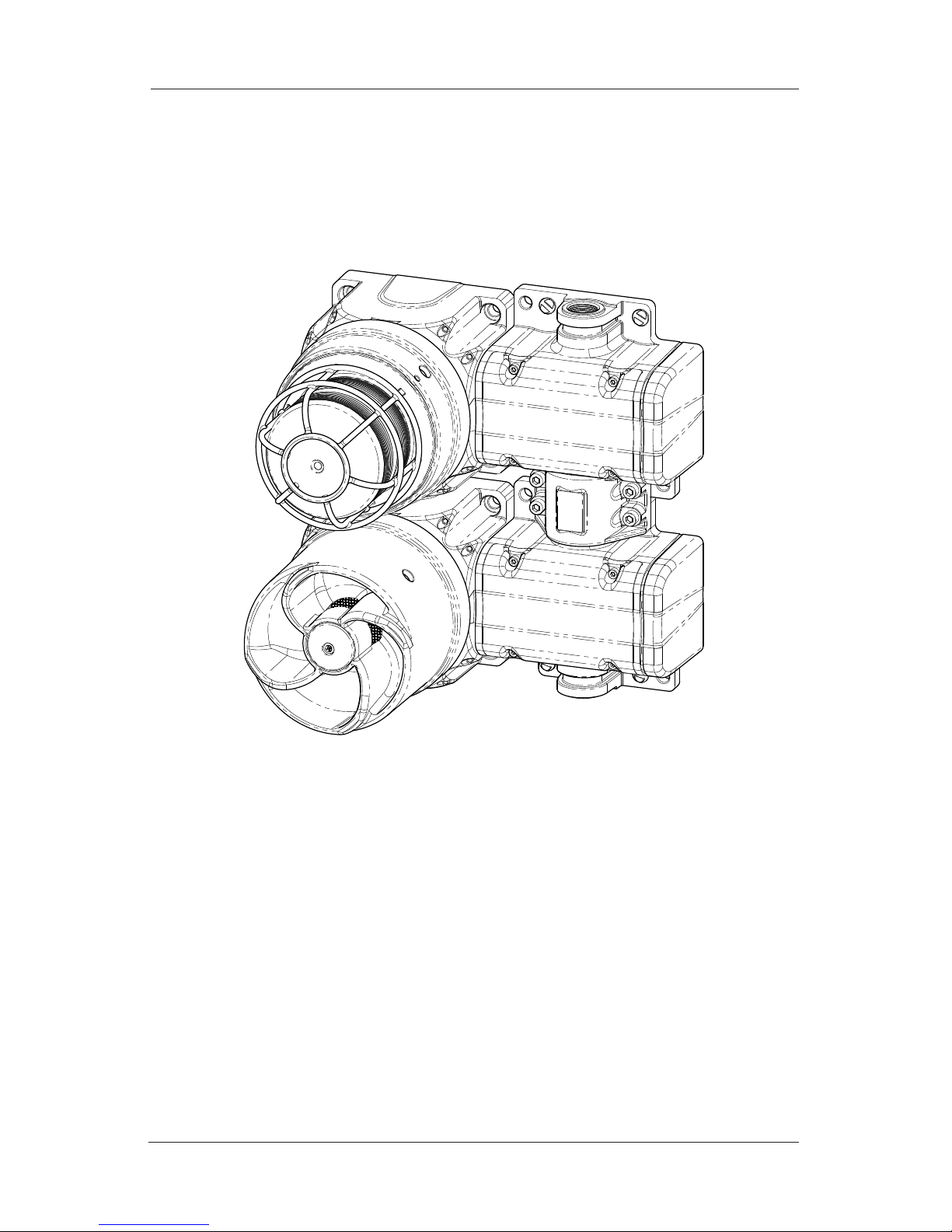
Creating Combination Fixtures in the Field
The Federal Signal Global Series Ex de products can be connected
together in the eld using interchangeable E-box end caps and a
proprietary coupling system (Figure 1).
Figure 1 Sounder and sounder combination xture
The proprietary coupling system allows for simple and cost effective,
wiring from product to product, often eliminating the need for
expensive Ex wiring practices and Ex rated glands. The E-box is
available only when factory installed on an Ex d unit or when used
as a E-box spacer adjoining an existing E-box. Please refer to the
accessories listed on page 28 for available options. When creating
certain xture combinations, it is necessary to replace E-box end caps
before mounting the product. If you are creating combination xtures,
refer to instruction manual 25500259 for specic instructions and
details.
Page 9
9
Installation and Maintenance Instructions
Model G-SND Global Series Sounder
A note about combination xtures: If the product is Ex db marked
only, it is for use in gas atmospheres. If the product is Ex db e marked,
it uses the increased-safety terminal enclosures and is only for gas
atmospheres. If the product is Ex tb marked, it is for installation in
dust atmospheres.
Mounting the G-SND Sounder
ATTACH THE SOUNDER SECURELY: To prevent injury, this
apparatus must be securely attached to the mounting surface
in accordance with the installation instructions. Use installersupplied fasteners suitable for the mounting surface.
The mounting method and the installer-supplied mounting hardware
depend on which of the two G-SND models you are installing:
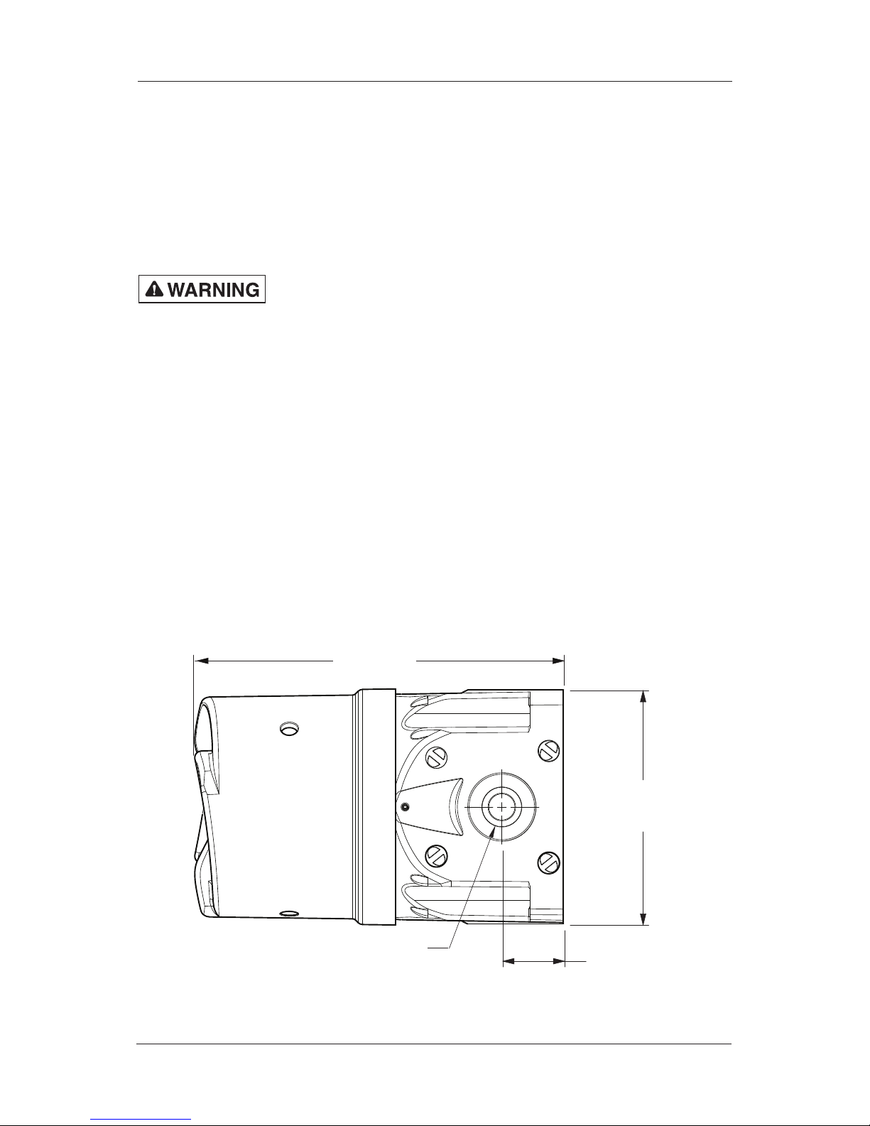
Mounting the Surface-Mount Ex d Sounder
Mount the sounder to a at surface using the four 8.5 mm mounting
holes. Use installer-supplied fasteners suitable for the surface to
which the device will be mounted.
Figure 2 Side view of Ex d sounder
132.6 mm
(5.22 in)
34.9 mm
(1.38 in)
2X M20 GLAND ENTRIES
190.6 mm
(7.50 in)
Page 10
10
Installation and Maintenance Instructions
Model G-SND Global Series Sounder
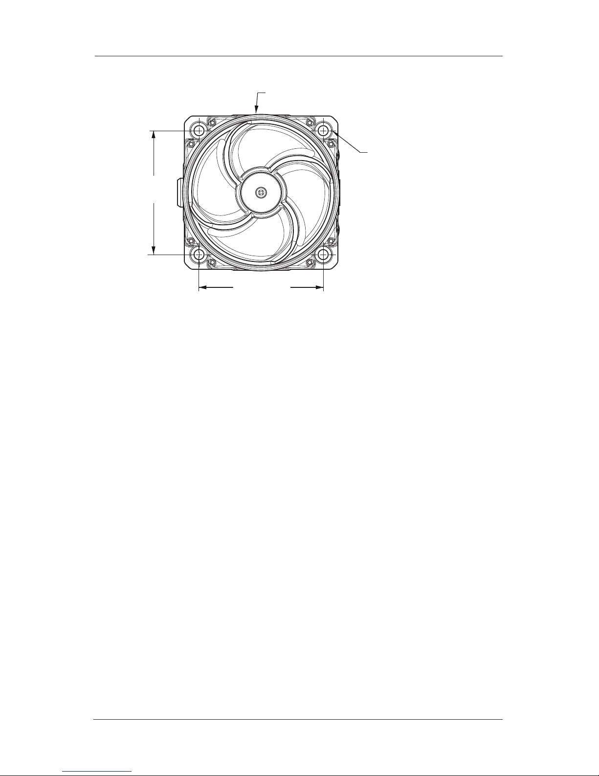
Figure 3 Front view of Ex d sounder
105.9 mm
(4.17 in
Ø133.8 mm (5.27 in)
4X COUNTER-BORED
HOLES TO FIT M8
SOCKET-HEAD
CAP SCREWS
105.9 mm
(4.17 in
)
Mounting the Ex d e Surface-Mount Sounder
Mount the sounder to a at surface using the six 8.5 mm mounting
holes. Use installer-supplied fasteners suitable for the surface to
which the device will be mounted.
Page 11

11
Installation and Maintenance Instructions
Model G-SND Global Series Sounder
Figure 4 Front view of Ex d e surface mount
2X Ø8.5 mm
103.2 mm
(4.06 in)
122.6 mm
(4.83 in)
3X M20
GLAND
ENTRIES
4X COUNTER-BORED
HOLES TO FIT M8
SOCKET-HEAD
CAP SCREWS
105.9 mm
(4.17 in)
23.2 mm
(0.91 in)
Page 12

12
Installation and Maintenance Instructions
Model G-SND Global Series Sounder
Figure 5 Side view of Ex d e surface mount
272.0 mm
(10.71 in)
190.6 mm
(7.50 in)
SEE ACCESSORIES FOR
REPLACEABLE E-BOX END CAPS
3X M20 GLAND ENTRIES
Page 13

13
Installation and Maintenance Instructions
Model G-SND Global Series Sounder
Safety Messages for Wiring
When installing and operating ame-proof electrical equipment,
the relevant national regulations for installation and operation
(e.g., EN60079-14, IEC Wiring Regulations and NEC/CEC)
must be observed.
• To avoid electrical shock hazards, do not connect wires when
power is applied. Failure to observe this warning may lead to
serious injury or death.
• To maintain the ame-proof integrity of the enclosure, DO NOT
damage the cover or threads while disassembling or reassembling
the unit.
• Painting and surface nishes, other than those applied by
Federal Signal Corporation, are not permitted.
• Cable termination should be in accordance with specications
applying to the application. Federal Signal recommends that all
cables and cores should be fully identied.
• Ensure that only the correct equipment-certied glands are
used and that the assembly is shrouded and correctly earthed.
Gland entries are M20-1.5 6H with an option for the M25 entry
on the end of the increased safety box models. See Table 4 on
page 29 for choosing correct cable entry devices for Equipment
in Potentially Explosive Atmospheres.
• Because of space limitations, ensure the cable cores within the
unit are not too slack.
• In all countries, the wiring must comply with all national and local
codes and standards.
• Ensure that all nuts, bolts, and xings are secure.
Page 14

14
Installation and Maintenance Instructions
Model G-SND Global Series Sounder
Preparing to Wire the Ex d Flameproof Models
SHOCK HAZARD: To avoid electrical shock hazards, do not
connect wires when power is applied. Failure to observe this
warning may lead to serious injury or death.
CIRCUIT BOARD DAMAGE: The DC sounders are polarity
sensitive, and MAY BE DAMAGED by incorrect electrical hookup.
When connecting the DC sounder to the voltage supply lines,
POLARITY MUST BE OBSERVED. In addition, damage will result
if the voltage rating of the particular model is exceeded by more
than 10 percent.
This section has wiring instructions for the ameproof models
G-SND 24 Vdc, 120 Vac, 220-240 Vac.
Ex d units are supplied with an eleven-position PCB mounted screw
terminal block. The maximum wire gauge is 4 mm2 (12 AWG).
The wire must be rated 85 °C or higher. Use only stranded cable to
terminate the sounder.
The cross-sectional area of the primary earth
(ground) must equal the cross-sectional area of the phase conductor.
Cable termination for these models should be in accordance with
specications applying to the application. It is recommended that all
cables and cores should be fully identied. Use the appropriate cable
gland for the application. Gland entry threads are M20-1.5 x 6H.
Tools needed:
• 1.5 mm A/F hexagon key
• 2 mm at-tip screwdriver
• No. 1 Phillips screwdriver
• Wire stripper
Page 15

15
Installation and Maintenance Instructions
Model G-SND Global Series Sounder
Figure 6 Ex d in/out PCB connections
VOLTAGE
SELECTOR
SWITCH
D8
D2
D1
D4
D3
J1
F1
S1
S2
F2
D7 D5D6
R1
DC
120
230AC
T4 T3 T2 T1 SEL EARTH L2 L2 L1 L1
Wiring the Ex d Models
To wire the Ex d ameproof sounder:
1. Unscrew the M3 hex set screw on the side of the housing one
full turn.
2. Remove the cover from the housing by turning the cover
counter-clockwise. Three 120-degree spaced reliefs are
provided for a 3/8 inch spanner wrench if needed. If the cover
will not unscrew, back out the set screw a few additional turns.
3. Loosen the captive Phillips screw retaining the driver/printed
circuit board (PCB).
4. Slide out the PCB until the terminals clear the housing.
Strip the wire insulation 6.5 mm (0.25 in). Maximum screw
tightening torque is 0.5 N•m (4.5 in-lb).
5. Follow the instructions starting below for your line voltage
and continue to Step 6 on page 19. Refer to Figure 6 for the
voltage selector switch and page 20 for the tone chart.
Page 16

16
Installation and Maintenance Instructions
Model G-SND Global Series Sounder
Figure 7 Locations of tone and volume switches
TONE
SELECTOR
SWITCH
VOLUME
CONTROL: FULL
CLOCKWISE
= MAX. VOLUME
220-240 Vac Operation (no remote switching of tones)
a. Set the voltage selector switches to 230 and AC.
b. Turn the tone selector switch to the desired tone.
c. Connect the line (hot) power source wire to the terminal
block position marked L1 on the PCB.
d. Connect the neutral (common) power source wire to the
terminal block position marked L2 on the PCB.
e. Connect ground wire to the terminal block position
marked EARTH.
120 Vac operation (no remote switching of tones)
a. Set the voltage selector switches to 120 and AC.
b. Turn the tone selector switch to the desired tone.
c. Connect the line (hot) power source wire to the terminal
block position marked L1 on the PCB.
d. Connect the neutral (common) power source wire to the
terminal block position marked L2 on the PCB.
Page 17

17
Installation and Maintenance Instructions
Model G-SND Global Series Sounder
e. Connect ground wire to the terminal block position
marked EARTH.
24 Vdc operation (no remote switching of tones)
a. Set the voltage selector switches to 230 and DC.
b. Turn the tone selector switch to the desired tone.
c. Connect the positive (+) power source wire to the
terminal block position marked L1 on the PCB.
d. Connect the negative (–) power source wire to the
terminal block position marked L2 on the PCB.
e. Connect ground wire to the terminal block position
marked EARTH.
220-240 Vac operation (remote switching of tones)
a. Set the voltage selector switches to 230 and AC.
b. Set the tone selector switch to 0.
c. Connect the line (hot) power source wire to the
terminal block position marked L1 on the PCB.
d. Connect the neutral (common) power source wire to
the terminal block position marked L2 on the PCB.
e. Connect ground wire to the terminal block position
marked EARTH.
f. Connect the common wire from the remote switching
device to the terminal block position marked SEL.
g. Connect the tone select wires from the remote
switching device to the terminal block positions
marked T1, T2, T3, and T4.
For 120 Vac operation (remote switching of tones)
a. Set the voltage selector switches to 120 and AC.
Page 18

18
Installation and Maintenance Instructions
Model G-SND Global Series Sounder
b. Set the tone selector switch to 0.
c. Connect the line (hot) power source wire to the
terminal block position marked L1 on the PCB.
d. Connect the neutral (common) power source wire to
the terminal block position marked L2 on the PCB.
e. Connect the ground wire to the terminal block
position marked EARTH.
f. Connect the common wire from remote switching device
to the terminal block position marked SEL.
g. Connect the tone select wires from remote switching
device to the terminal block positions marked T1, T2,
T3, and T4.
24 Vdc operation (remote switching of tones with local power)
a. Set the voltage selector switches to 230 and DC.
b. Set the tone selector switch to 0.
c. Connect the negative (–) power source wire to the
terminal block position marked L2 on the PCB.
d. Connect the positive (+) power source wire to the
terminal block position marked L1 on the PCB.
e. Connect the ground wire to the terminal block
position marked EARTH.
f. Connect common wire from remote switching device
to the terminal block position marked SEL.
g. Connect tone select wires from remote switching
device to the terminal block positions marked T1, T2,
T3, and T4.
For 24 Vdc operation (remote switching of tones with
remote power)
Page 19

19
Installation and Maintenance Instructions
Model G-SND Global Series Sounder
a. Set the tone selector switch to 0.
b. Connect the negative (–) power source wire to the
terminal block position marked L2 on the PCB.
c. Connect the positive (+) power source/select wires
to the terminal block positions marked T1, T2, T3,
and T4.
d. Connect the ground wire to the terminal block position
marked EARTH.
6. Insert the PCB into the enclosure and fully tighten the PCB
captive screw.
7. Place the cover on the housing and tighten it by turning it
clockwise.
8. To ensure O-ring compression, the cover must be fully seated
against the housing when the threads are tightened. Turn
the M3 set screw on the side of the housing until the screw
contacts the housing.
9. Ensure that the unused wire entry is sealed with the provided
brass M20-1.5 x 6 g stopping plug (equipment-certied).
Page 20

20
Installation and Maintenance Instructions
Model G-SND Global Series Sounder
Table 1 Tone chart
Tone (Position) Description Frequency Duration
0 (0) Off
1 (1) Two Tone 588 Hz
714 Hz
0.25 s
0.25 s
2 (2) Swept 600 Hz to 700 Hz 0.5 s
3 (3) Warble 1000 Hz/1400 Hz
Silence
Warble
Silence
0.4 s
0.25 s
0.4 s
0.2 s
4 (4) Constant 700 Hz 700 Hz
5 (5) Simulated Bell ~ 3 rings per s
6 (6)
Swept
1.6 kHz to 1.2 kHz
1.2 kHz to 2.6 kHz 6 cycles per s
7 (7) Two Tone 1 kHz
700 Hz
0.4 s
0.4 s
8 (8) 700 Hz 700 Hz
Silence
0.25 s
0.25 s
9 (9) Swept 400 Hz to 1.6 Hz
Constant 1.2 kHz
1.2 kHz to 400 kHz
Silence
1 s
2 s
1 s
5 s
10 (A) Swept 500 Hz to 770 Hz 0.5 s
11 (B) 1 KHz 1 KHz
Silence
1 s
1 s
*12 (C)
Constant 1 kHz 1 kHz
13 (D) Two Tone 700 Hz
500 Hz
0.5 s
0.5 s
14 (E) Warble 1 kHz to 1.4 kHz 10 cycles
per s
15 (F) Swept 1.2 kHz 400 Hz 1 s
*Factory setting
Page 21

21
Installation and Maintenance Instructions
Model G-SND Global Series Sounder
Preparing to Wire the Ex de Increased Safety Models
SHOCK HAZARD: To avoid electrical shock hazards, do not
connect wires when power is applied. Failure to observe this
warning may lead to serious injury or death.
This section has wiring instructions for the three increased safety models:
• G-SND 24 Vdc
• G-SND 120 Vac
• G-SND 240 Vac
Ex de units are supplied with a six-pole, spring-tension clamp style
terminal block. The maximum wire gauge is 4.0 mm2 (12 AWG).
The wire must be rated 85 °C or higher. Use only stranded cable to
terminate the sounder.
The cross-sectional area of the primary earth
(ground) must equal the cross-sectional area of the phase conductor.
Cable termination should be in accordance with specications
applying to the application. It is recommended that all cables and
cores should be fully identied. Use the appropriate cable gland for
the application. Gland entry threads are M20-1.5 6H.
Conductive metalwork, including cable glands, must be a
minimum of 5 mm away from the terminals.
Leads connected to the terminals shall be insulated for the
appropriate voltage and this insulation shall extend to within
1 mm of the metal of the terminal throat.
The G-SND terminal block is supplied with two conductors per
pole. The terminal block allows for easy supply-in and loop-out
wiring to connect sounders in series.
Tools needed:
• 3.0 mm A/F hexagon key
• No. 1 Phillips screwdriver
• Wire stripper
Page 22

22
Installation and Maintenance Instructions
Model G-SND Global Series Sounder
Wiring the Ex de Models
CIRCUIT BOARD DAMAGE: The DC sounders are polarity
sensitive, and MAY BE DAMAGED by incorrect electrical
hookup. When connecting the DC sounder to the voltage supply
lines, POLARITY MUST BE OBSERVED. In addition, damage will
result if the voltage rating of the particular model is exceeded by
more than 10 percent.
To wire the Ex de models:
1. Unscrew the four M4 socket-head cap screws and remove
the terminal box cover.
2. Strip the wire insulation 8 mm to 9 mm (0.33 in).
NOTE: When using more than one single or multiple strand
lead, the connection into either side of any terminal must be
joined in a suitable manner, e.g. two conductors into a single
insulated crimped bootlace ferrule.
3. To connect wires, press the pushbutton on the terminal block
with a Phillips screwdriver and insert the wire into the round
opening. Release pushbutton to make connection.
4. Follow the instructions starting below for your line voltage and
continue to Step 5 on page 25. Refer to Figure 6 on page 15
for the voltage selector switch and page 20 for the tone chart.
Figure 8 Connections for DC or AC Ex d e sounder
Alt04Alt03Alt01L1/+ L2/- Alt02
Alt04Alt03Alt01L1/+ L2/- Alt02
Page 23

23
Installation and Maintenance Instructions
Model G-SND Global Series Sounder
220-240 Vac operation (no remote switching of tones)
a. Connect the line (hot) power-source wire to the position
marked L1/+ on the terminal block.
b. Connect the neutral (common) power-source wire to the
position marked L2/- on the terminal block.
c. Connect the ground wire to the position marked
Alt01 on the terminal block.
120 Vac operation (no remote switching of tones)
a. Connect the line (hot) power-source wire to the position
marked L1/+ on the terminal block.
b. Connect the neutral (common) power-source wire to the
position marked L2/- on the terminal block.
c. Connect the ground wire to the position marked
Alt01 on the terminal block.
24 Vdc operation (no remote switching of tones)
a. Connect the positive (+) power-source wire to the
position marked L1/+ on the terminal block.
b. Connect the negative (–) power-source wire to the
terminal block position marked L2/- on the terminal
block.
c. Connect the ground wire to the position marked
Alt01 on the terminal block.
220-240 Vac operation (remote switching of tones)
a. Connect the line (hot) power-source wire to the position
marked L1/+ on the terminal block.
b. Connect the neutral (common) power-source wire to the
position marked L2/- on the terminal block.
Page 24

24
Installation and Maintenance Instructions
Model G-SND Global Series Sounder
c. Connect the ground wire to the position marked
Alt01 on the terminal block.
d. Connect the common wire from remote switching device
to the terminal block position marked Alt02.
e. Connect the tone-select wires from the remote switching
device to the terminal block positions marked Alt03
and Alt04. Please note that only two tones are remotely
selectable on Ex de 220-240 Vac units.
120 Vac operation (remote switching of tones)
a. Connect the line (hot) power source wire to the position
marked L1/+ on the terminal block.
b. Connect the neutral (common) power source wire to the
position marked L2/- on the terminal block.
c. Connect the ground wire to the position marked Alt01 on
the terminal block.
d. Connect the common wire from the remote switching
device to the terminal block position marked Alt02.
e. Connect the tone-select wires from the remote switching
device to the terminal block positions marked Alt03
and Alt 04. Please note that only two tones are remotely
selectable on Ex de 120 Vac units.
24 Vdc operation (remote switching of tones with remote power)
a. Connect the negative (–) power source wire to the
position marked L2/- on the terminal block.
b. Connect the positive (+) power source/select wires to
the terminal block positions marked Alt02, Alt03, Alt04.
Please note that only three tones are remotely selectable
on Ex de 24 Vdc units.
c. Connect the ground wire to the position marked
Alt01 on the terminal block.
Page 25

25
Installation and Maintenance Instructions
Model G-SND Global Series Sounder
5. Secure the cover on the terminal box with the four M4
screws. Ensure that the gasket is properly seated to maintain
IP rating. Do not overtighten the screws.
Selecting the Tone for Ex de Models
All effective warning sounders produce loud sounds, which
may cause, in certain situations, permanent hearing loss. Take
appropriate precautions such as hearing protection.
To select the tone for Ex de models:
1. Unscrew the M3 hex set screw on the side of the housing one
full turn.
2. Remove the cover from the housing by turning the cover
counter-clockwise. Three 120-degree spaced reliefs are
provided for a 3/8 inch spanner wrench if needed. If the cover
will not unscrew, back out the set screw a few additional turns.
3. Loosen the captive Phillips screw retaining the driver/printed
circuit board (PCB).
4. Slide out the PCB and set the tone selector switch to the
desired tone.
5. Insert the driver/PCB into the enclosure taking care not to
pinch the wiring and fully tighten the PCB captive screw.
6. Place cover on housing and tighten it by turning it clockwise.
7. To ensure O-ring compression, the cover must be fully seated
against the housing when the threads are tightened. Turn
the M3 set screw on the side of the housing until the screw
contacts the housing.
Page 26

26
Installation and Maintenance Instructions
Model G-SND Global Series Sounder
Safety Messages to Maintenance Personnel
Listed below are some important safety instructions and precautions
you should follow:
• Read and understand all instructions before operating this system.
• Repair of amepaths is not recommended.
• If you acquired a signicant quantity of units, then it is
recommended that spares are also made available.
• To avoid electrical shock hazards, do not connect wires when
power is applied. Failure to observe this warning may lead to
serious injury or death.
• Any maintenance to the sounder system must be performed by a
trained electrician who is thoroughly familiar with all applicable
national and local codes in the country of use.
• Any maintenance to the sounder system must be done with power
turned off.
• Check the sounder periodically to ensure that the effectiveness of
the device has not been reduced because it has been clogged with
a foreign substance or because objects have been placed in front
of it.
• Never alter the unit in any manner. Safety of the unit may be
affected if additional openings or other alterations are made to the
internal components or housing.
• The nameplate, which may contain cautionary or other information
of importance to maintenance personnel, should NOT be obscured
in any way. Ensure that the nameplate remains readable.
• After performing any maintenance, test the sounder system to
ensure that it is operating properly.
Failure to follow all safety precautions and instructions may result in
property damage, serious injury, or death.
Page 27

27
Installation and Maintenance Instructions
Model G-SND Global Series Sounder
Maintaining the Sounder
EXPLOSION HAZARD: To prevent ignition of hazardous
atmosphere, disconnect the sounder from the supply circuit
before opening it. Do not open the sounder in the presence of
explosive gases in the atmosphere. Failure to follow this warning
may result in serious injury or death.
During the working life of the sounder, it should require little or no
maintenance. The non-metallic housing will resist attack by most
acids, alkalis, and chemicals and is as resistant to concentrated acids
and alkalis as most metal products. However, if abnormal or unusual
environment conditions occur due to plant damage or accident, etc.,
visual inspection of the sounder is recommended.
Cleaning the Enclosure
The enclosure should be cleaned periodically with a damp cloth to
maintain maximum sound output. Periodic checks should be made
to ensure the effectiveness of this device has not been reduced
because the sounder has become clogged with a foreign substance
or because objects have been placed in front of the sounder.
Lubricating the Threaded Joints
A silicone based, non-hardening, chemically compatible grease can
be applied if required.
Do not paint this device after installation and do not change the
factory-appliednish.
Ordering Replacement Parts and Accessories
A replacement part for the driver/PCB assembly and accessories
are listed in Tables 2 and 3 on page 28. Due to certication, certain
component parts are not available for eld replacement. Sounders
with this type of damage must be either replaced entirely or returned
to Federal Signal for service. Refer to instruction manual 25500259 for
accessory and replacement part assembly and operating instructions.
Page 28

28
Installation and Maintenance Instructions
Model G-SND Global Series Sounder
To order, call Federal Signal Customer Support at 708-534-4756 or
877-289-3246.
Table 2 Replacement Part
Description Part Number
Multi-voltage G-SND Sounder Kit (Includes PCBAs,
Bracket, Driver, & Mounting Screws)
K859500821-02
Table 3 Accessories
Description Part Number
Indicator Ring/Legend Kit, Black G-KIT-RP-BK
Indicator Ring/Legend Kit, Blue G-KIT-RP-B
Indicator Ring/Legend Kit, Green G-KIT-RP-G
Indicator Ring/Legend Kit, Magenta G-KIT-RP-M
Indicator Ring/Legend Kit, Red G-KIT-RP-R
Indicator Ring/Legend Kit, Yellow G-KIT-RP-Y
E-Box Endcap with M20 Opening K859500805-02
E-Box Endcap with M20 Opening with Flange K859500805-03
E-Box Endcap with M25 Opening K859500805-01
E-Box Cover Assembly (Includes two terminal
blocks, mounting plate, retention hardware)
K859501414
E-Box Coupler Kit K859501228
In-Line E-Box Coupler Kit G-KIT-EC180
90-Degree E-Box Coupler Kit G-KIT-EC90
Extension Box Spacer Kit G-KIT-EXTB
Single Trunnion Kit G-KIT-ST
Dual Trunnion Kit G-KIT-DT
Adapter, M20 Male to 1/2” Female NPT K231246A
Adapter, M20 Male to 3/4” Female NPT K231247
Page 29

29
Installation and Maintenance Instructions
Model G-SND Global Series Sounder
Table 4 Choosing cable-entry devices for Equipment in Potentially
Explosive Atmospheres
Models Ex Atmospheres
Cable Entry Devices (cable
glands, stopping plugs, etc.
G-SND-XXX-D
(Ex db surface
mount)
Gas Cable entry devices shall
be equipment certied as
ameproof. To maintain the
ingress protection of the
ameproof sounder enclosure,
we recommend the cable entry
device be IP66 certied.
G-SND-XXX-E Gas For the ameproof enclosure,
cable entry devices shall
be equipment certied as
ameproof. To maintain the
ingress protection of the
ameproof enclosure we
recommend the cable entry
device be IP66 certied. For
the increased safety terminal
enclosures (terminal boxes),
cable entry devices shall
be equipment certied as
increased safety and shall
maintain an IP rating of IP54.
G-SND-XXX-D
(Ex db surface
mount)
G-SND-XXX-E
(Ex db e surface
mount)
Dust Cable entry devices for the
and terminal enclosures shall
be equipment certied as
dust protected. To maintain
the ingress protection of
the sounder and terminal
enclosures the cable entry
devices shall be IP6X certied.
Page 30

30
Installation and Maintenance Instructions
Model G-SND Global Series Sounder
UL Fire Alarm Certications
The audible sounder models that are powered using 24 Vdc input
are Listed by Underwriters Laboratories (UL) for use in re alarm
applications. The 120 Vac and 230 Vac inputs have not been
evaluated. These models have the following nomenclature:
G-SND-MV-D, G-SND-MV-D, G-SND-MV-T, and G-SND-024-E.
They have an electrical rating of 515 mA maximum at 24 regulated
voltage Vdc (16 Vdc to 33 Vdc).
NOTE: UL only evaluated this product to the stated operational voltage
range. It was not evaluated to 80% to 110%. of the voltage range.
The sounder is factory-set with the tone selector switch set to the
No. 12 setting. This is a constant 1 kHz tone. This is the only tone
setting that has been evaluated for re alarm applications. At this tone
the sounder has a sound pressure level of 79.0 dB. See Figure 9 for
the dispersion characteristics.
The units can be mounted on a wall or ceiling and have no
mounting orientation restriction. For specic installation and wiring
requirements, refer to local codes such as the National Code (NFPA70)
and the National Fire Alarm and Signaling Code (NFPA72).
Figure 9 Dispersion characteristics for audible signal devices
AUDIBLE SIGNAL DEVICE
3 m 3 m
20
º
–6 dB –6 dB
–3
dB –3 dB
99
dB
50
º
Page 31

31
Installation and Maintenance Instructions
Model G-SND Global Series Sounder
Do not paint this device after installation and do not change the
factory-appliednish.
Getting Technical Support and Service
The Federal Signal factory provides technical assistance with any
problems that cannot be handled locally. Any units returned to Federal
Signal for service, inspection, or repair must be accompanied by a
Return Material Authorization (RMA). Obtain a RMA from a local
Distributor or Manufacturer’s Representative. Please provide a brief
explanation of the service requested, or the nature of the malfunction.
For technical support and service, visit:
https://www.fedsig.com/technical-support
https://www.fedsig.com/service-center
 Loading...