

Federal Signal Corporation Global G-SPA-D Series, Global G-SPA-E Series, Global G-SPA-T Series, Global G-SPA Series, Global Series Installation And Maintenance Instructions Manual
Page 1

Global Series
Model G-SPA Amplied Speaker
For Use in Hazardous Locations
Installation and
Maintenance Instructions
To view this manual in Portuguese, go to www.federalsignal-indust.com.
To view this manual in Mandarin, go to www.federalsignal-indust.com.
To view this manual in Russian, go to www.federalsignal-indust.com.
25500188
Rev. A0 0815
Printed in U.S.A.
Page 2

Warranty – Seller warrants all goods for ve years on parts and 2-1/2 years
on labor, under the following conditions and exceptions: Seller warrants that
all goods of Seller's manufacture will conform to any descriptions thereof
for specications which are expressly made a part of this sales contract and
at the time of sale by Seller such goods shall be commercially free from
defects in material or workmanship. Seller reserves the right at the Seller’s
discretion to “Repair and Return” or “Replace” any item deemed defective
during the warranty period. This warranty does not cover travel expenses,
the cost of specialized equipment for gaining access to the product, or labor
charges for removal and reinstallation of the product. This warranty shall be
ineffective and shall not apply to goods that have been subjected to misuse,
neglect, accident, damage, improper maintenance, or to goods altered or
repaired by anyone other than Seller or its authorized representative, or if
ve years have elapsed from the date of shipment of the goods by Seller with
the following exceptions: lamps and strobe tubes are not covered under this
warranty. Outdoor warning sirens and controllers manufactured by Federal
Warning Systems are warranteed for two years on parts and one year on labor.
No agent, employee, representative or distributor of Seller has any authority
to bind the Seller to any representation, afrmation, or warranty concerning
the goods and any such representation, afrmation or warranty shall not be
deemed to have become a part of the basics of the sales contract and shall
be unenforceable. THE FOREGOING WARRANTIES ARE EXCLUSIVE
AND IN LIEU OF ALL OTHER WARRANTIES OR MERCHANTABILITY,
FITNESS FOR PURPOSE AND OF ANY OTHER TYPE, WHETHER
EXPRESS OR IMPLIED. These warranties shall not apply unless Seller
shall be given reasonable opportunity to investigate all claims for allegedly
defective goods. Upon Seller's instruction a sample only of allegedly defective
goods shall be returned to Seller for its inspection and approval. The basis of
all claims for alleged defects in the goods not discoverable upon reasonable
inspection thereof pursuant to paragraph 8 hereof must be fully explained
in writing and received by Seller within thirty days after Buyer learns of the
defect or such claim shall be deemed waived.
Industrial Systems
2645 Federal Signal Drive • University Park, IL 60484-3167
Tel: 708-534-4756 • 877-289-3246 • Fax: 708-534-4852
Email: elp@federalsignal.com • www.federalsignal-indust.com
Page 3

Contents
Safety Messages to Installers and Users ...................................5
Certication ...................................................................................6
Unpacking the Amplied Speaker ..............................................7
Creating Combination Fixtures in the Field ...............................7
Mounting the Amplied Speaker .................................................8
Mounting the Trunnion-Mount Amplied speaker ............................ 8
Mounting the Surface-Mount Ex d Amplied Speaker ................... 10
Mounting the Ex de Surface-Mount Amplied Speaker ...................11
Safety Messages for Wiring .......................................................13
Connecting to the Terminal Block ............................................14
Preparing to Wire the Ex d Flameproof Models .......................14
Wiring the Ex d Models ................................................................... 15
Adjusting the Sound Pressure and Audio Input (Ex d) .................... 17
Preparing to Wire the Ex de Increased Safety Models ............19
Wiring the Ex de Models ................................................................. 20
Adjusting the Sound Pressure and Audio Input (Ex de) .................. 22
Safety Messages to Maintenance Personnel ...........................23
Maintaining the Amplied Speaker ...........................................24
Cleaning the Enclosure .................................................................... 24
Lubricating the Threaded Joints ....................................................... 24
Ordering Replacement Parts and Accessories .......................24
Getting Repair Service or Technical Assistance .....................25
Returning the Product for Credit ..............................................27
Model G-SPA Global Series Amplied Speaker
3
Page 4

Contents
Tables
Table 1 Replacement part ..................................................................... 25
Table 2 Accessories .............................................................................. 25
Table 3 Choosing cable-entry devices for Equipment
in Potentially Explosive Atmospheres .....................................................26
Figures
Figure 1 Beacon and amplied speaker combination xture .................. 8
Figure 2 Bracket dimensions .................................................................. 9
Figure 3 Front view of trunnion-mount amplied speaker....................... 9
Figure 4 Side view of trunnion mount amplied speaker ...................... 10
Figure 5 Front view of Ex d amplied speaker...................................... 10
Figure 7 Front view of Ex de surface mount ......................................... 11
Figure 8 Side view of Ex de surface mount .......................................... 12
Figure 9 Disengaging a terminal block spring clamp ............................ 14
Figure 10 Ex d in/out PCB connections ................................................ 15
Figure 11 Location of VR1 potentiometer (sound pressure) ................. 17
Figure 12 Location of jumper JP3 (audio input) .................................. 18
Figure 13 Connections for DC or AC Ex de amplied speaker ............. 20
© 2015 Federal Signal Corporation. All rights reserved.
4
Model G-SPA Global Series Amplied Speaker
Page 5

Installation and Maintenance Instructions
Safety Messages to Installers and Users
It is important to follow all instructions shipped with this product.
This amplied speaker is to be installed by a trained electrician who
is thoroughly familiar with and will follow all applicable national and
local codes in the country of use.
This amplied speaker should be considered a part of the warning
system and not the entire warning system.
The selection of the mounting location for the amplied speaker, its
controls and the routing of the wiring are to be accomplished under
the direction of the facilities engineer and the safety engineer. In
addition, listed below are some other important safety instructions and
precautions you should follow:
• Read and understand all instructions before installing or operating
this equipment.
• To avoid electrical shock hazards, do not connect wires when
power is applied. Failure to observe this warning may lead to
serious injury or death.
• Never alter the unit in any manner. Safety in hazardous locations
may be endangered if additional openings or other alterations are
made in units specically designed for use in these locations.
• Do not connect this amplied speaker to the system when power
is on.
• All effective warning speakers produce loud sounds, which
may cause, in certain situations, permanent hearing loss. Take
appropriate precautions such as hearing protection. The device
should be installed far enough away from potential listeners to
limit their exposure while still maintaining its effectiveness.
• After installation, ensure that all threaded joints are properly
tightened.
Model G-SPA Global Series Amplied Speaker
5
Page 6

Installation and Maintenance Instructions
• After installation, test the amplied speaker system to ensure that
it is operating properly
• Keep the unit tightly closed when in operation.
• After testing is complete, provide a copy of this instruction sheet
to all personnel.
• Brass inserts have the potential to store charge when they are not
plugged. Consideration should be taken to prevent these from
becoming a sparking hazard.
• Establish a procedure to routinely check the amplied speaker
system for proper activation and operation.
Failure to follow all safety precautions and instructions may result in
property damage, serious injury, or death.
Certication
Certicate Nos.: ATEX Cert No.: Baseefa15ATEX0155X
IECEx Cert No.: IECEx BAS 15.0104X
ATEX coding: II 2 G D
Protection: Ex db IIB T5 Gb or Ex db e IIB T5 Gb
Ex tb IIIC T100°C Db IP66 (Tamb = -50°C to + 49°C)
Ex db IIC T4 Gb or Ex db e IIC T4 Gb
Ex tb IIIC T135°C Db IP66 (Tamb = -50°C to + 60°C)
Standards: EN60079-0: 2012 +A11:2013, EN60079-1: 2014,
EN60079-7: 2007, EN60079-31: 2014, IEC60079-0: 6th Ed.,
IEC 60079-1: 7th Ed., IEC 60079-7: 4th Ed.,
IEC 60079-31:2nd Ed
Specic Conditions of Use:
1. The Modular Audible Device enclosure incorporates a sinter and
the volume is greater than 100 cm3, therefore use of the Modular
Audible Device in carbon disulphide gas atmospheres is not
permitted.
2. The Modular Audible Device has external non-metallic surfaces
which may provide electrostatic charging hazard. See the
manufacturer's instructions for further information.
6
Model G-SPA Global Series Amplied Speaker
Page 7

Installation and Maintenance Instructions
3. The Modular Audible Device has metallic components in the non-
metallic walls of the enclosure which can store electrical charge
and therefore may provide a potential electrostatic discharge.
The metallic brass inserts have a capacitance of 24 pF. See the
manufacturer's instructions for further information.
Unpacking the Amplied Speaker
After unpacking the amplied speaker, examine it for damage that
may have occurred in transit. If it has been damaged, do not attempt to
install or operate it. File a claim immediately with the carrier, stating the
extent of the damage. Carefully check all envelopes, shipping labels,
and tags before removing or discarding them. Disposal of all shipping
materials must be carried out in accordance with national and local
codes and standards. If any parts are missing, please call Federal Signal
Customer Support at +1 708-534-4756 or +1 877-289-3246.
Creating Combination Fixtures in the Field
The Federal Signal Global Series Ex de products can be connected
together in the eld using interchangeable E-box end caps and a
proprietary coupling system.
The proprietary coupling system allows for simple and cost effective,
wiring from product to product often eliminating the need for
expensive Ex wiring practices and Ex rated glands. The E-box is
available only when factory installed on an Ex d unit or when used
as a E-box spacer adjoining an existing E-box. Please refer to the
accessories listed on page 25 for available options. When creating
certain xture combinations, it is necessary to replace E-box end caps
before mounting the product. If you are creating combination xtures,
refer to instruction manual 25500259 for specic instructions and
details.
A note about combination xtures: If the product is Ex db marked
only, it is for use in gas atmospheres. If the product is Ex db e marked,
it uses the increased-safety terminal enclosures and is only for gas
atmospheres. If the product is Ex tb marked, it is for installation in
dust atmospheres.
Model G-SPA Global Series Amplied Speaker
7
Page 8
Installation and Maintenance Instructions
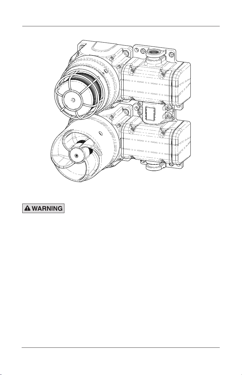
Figure 1 Beacon and amplied speaker combination xture
Mounting the Amplied Speaker
ATTACH THE AMPLIFIED SPEAKER SECURELY: To prevent injury,
this apparatus must be securely attached to the mounting surface
in accordance with the installation instructions. Use installersupplied fasteners suitable for the mounting surface.
The mounting method and the installer-supplied mounting hardware
depend on which of the three G-SPA models you are installing:
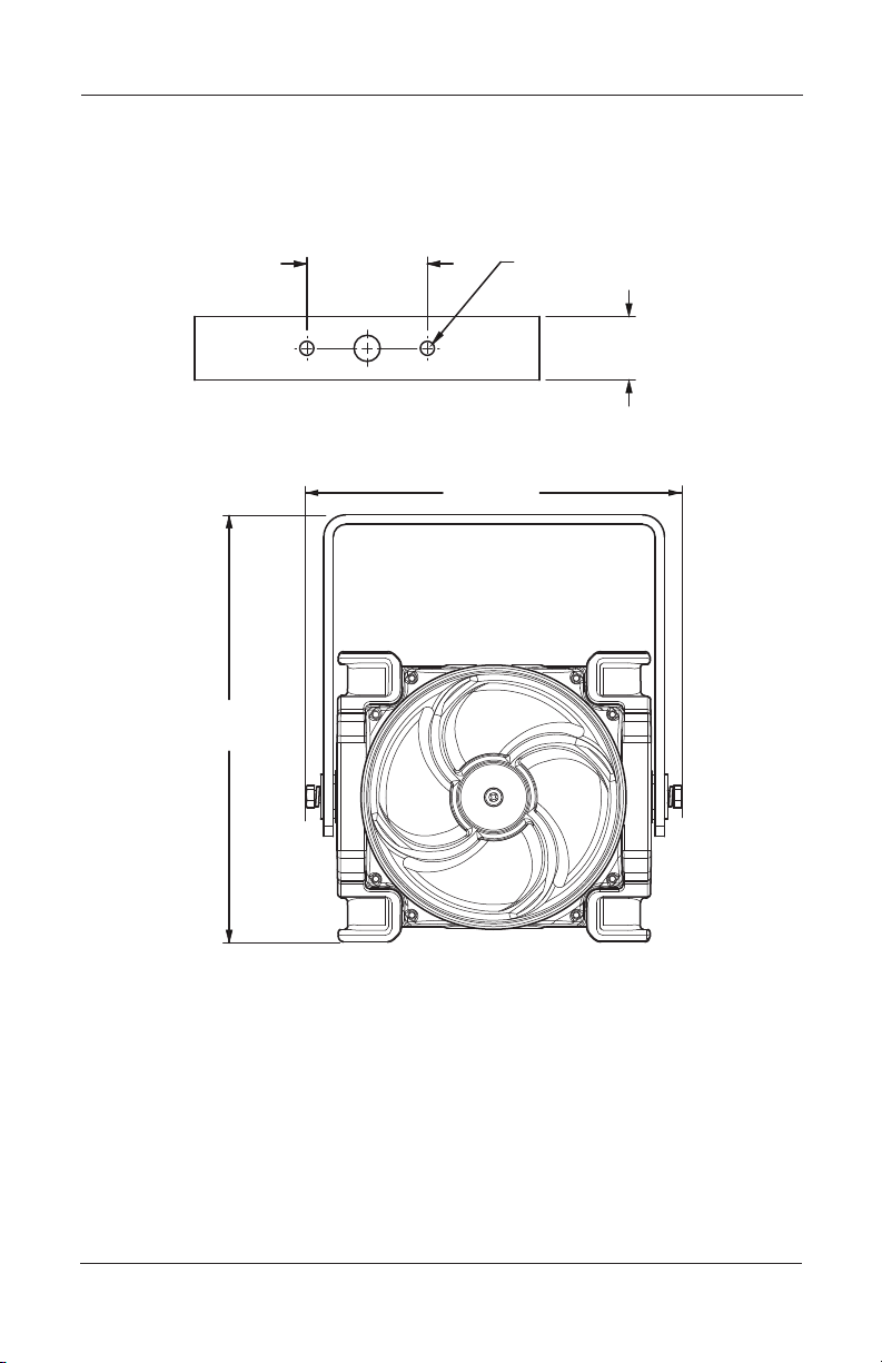
Mounting the Trunnion-Mount Amplied speaker
For the amplied speaker dimensions, see Figures 3 on page 9 and
4 on page 10. Mount the trunnion bracket to a at surface using
the two 7.0 mm mounting holes (Figure 2). Use installer-supplied
fasteners suitable for the surface to which the device will be
mounted.
8
Model G-SPA Global Series Amplied Speaker
Page 9
Installation and Maintenance Instructions
60.0 mm
2X M6 SCREW HOLE
189.2 mm
To adjust the vertical angle of the amplied speaker, loosen
the fasteners on the mounting bracket to disengage the ratchet.
Vertically aim the amplied speaker, and tighten the fasteners.
Figure 2 Bracket dimensions
(2.36 in)
31.8 mm
(1.25 in)
Figure 3 Front view of trunnion-mount amplied speaker
(7.45 in)
215.2 mm
(8.47 in)
Model G-SPA Global Series Amplied Speaker
9
Page 10

Installation and Maintenance Instructions
Ø133.8 mm (5.27 in)
4X COUNTER-BORED
Figure 4 Side view of trunnion mount amplied speaker
190.6 mm
(7.50 in)
Mounting the Surface-Mount Ex d Amplied Speaker
Mount the amplied speaker to a at surface using the four 8.5 mm
mounting holes. Use installer-supplied fasteners suitable for the
surface to which the device will be mounted.
10
Figure 5 Front view of Ex d amplied speaker
105.9 mm
(4.17 in
105.9 mm
)
(4.17 in
Model G-SPA Global Series Amplied Speaker
HOLES TO FIT M8
SOCKET-HEAD
CAP SCREWS
Page 11

Installation and Maintenance Instructions
(4.83 in)
4X COUNTER-BORED
Mounting the Ex de Surface-Mount Amplied Speaker
Mount the amplied speaker to a at surface using the six 8.5 mm
mounting holes. Use installer-supplied fasteners suitable for the
surface to which the device will be mounted.
Figure 7 Front view of Ex de surface mount
HOLES TO FIT M8
SOCKET-HEAD
CAP SCREWS
105.9 mm
(4.17 in)
23.2 mm
(0.91 in)
2X Ø8.5 mm
3X M20
GLAND
ENTRIES
103.2 mm
(4.06 in)
122.6 mm
Model G-SPA Global Series Amplied Speaker
11
Page 12

Installation and Maintenance Instructions
272.0 mm
Figure 8 Side view of Ex de surface mount
190.6 mm
(7.50 in)
(10.71 in)
3X M20 GLAND ENTRIES
REPLACEABLE E-BOX END CAPS
12
SEE ACCESSORIES FOR
Model G-SPA Global Series Amplied Speaker
Page 13

Installation and Maintenance Instructions
Safety Messages for Wiring
When installing and operating ame-proof electrical equipment,
the relevant national regulations for installation and operation (e.g.,
EN60079-14, IEC Wiring Regulations and NEC/CEC) must be
observed.
• To avoid electrical shock hazards, do not connect wires when
power is applied. Failure to observe this warning may lead to
serious injury or death.
• To maintain the ame-proof integrity of the enclosure, DO NOT
damage the cover or threads while disassembling or reassembling
the unit.
• Painting and surface nishes, other than those applied by Federal
Signal Corporation, are not permitted.
• Cable termination should be in accordance with specications
applying to the application. Federal Signal recommends that all
cables and cores should be fully identied.
• Ensure that only the correct equipment-certied glands are used
and that the assembly is shrouded and correctly earthed. Gland
entries are M20-1.5 6H with an option for the M25 entry on the
end of the increased safety box models. See Table 3 on page 30
for choosing correct cable entry devices for Equipment in
Potentially Explosive Atmospheres.
• Because of space limitations, ensure the cable cores within the
unit are not too slack.
• In all countries, the wiring must comply with all national and local
codes and standards.
• Ensure that all nuts, bolts, and xings are secure.
Model G-SPA Global Series Amplied Speaker
13
Page 14

Installation and Maintenance Instructions
Connecting to the Terminal Block
The terminal block for all models uses a spring clamp connection
to engage the wire. To disengage the clamp, insert the tip of the
screwdriver into the small openings near the top and press down. Insert
the stripped wire into the larger opening and remove the screwdriver to
engage the wire clamp.
Figure 9 Disengaging a terminal block spring clamp
Preparing to Wire the Ex d Flameproof Models
SHOCK HAZARD: To avoid electrical shock hazards, do not
connect wires when power is applied. Failure to observe this
warning may lead to serious injury or death.
CIRCUIT BOARD DAMAGE: The DC amplied speakers are
polarity sensitive, and MAY BE DAMAGED by incorrect electrical
hookup. When connecting the DC amplied speaker to the voltage
supply lines, POLARITY MUST BE OBSERVED. In addition,
damage will result if the voltage rating of the particular model is
exceeded by more than 10 percent.
This section has wiring instructions for the ameproof models
G-SPA 24 Vdc, 120 Vac, 220-240 Vac.
The maximum wire gauge is 2.5 mm2 (12 AWG). The wire must
be rated 85 °C or higher. Use only stranded cable to terminate the
amplied speaker.
The cross-sectional area of the primary earth
(ground) must equal the cross-sectional area of the phase conductor.
14
Model G-SPA Global Series Amplied Speaker
Page 15

Installation and Maintenance Instructions
Cable termination for these models should be in accordance with
specications applying to the application. It is recommended that all
cables and cores should be fully identied. Use the appropriate cable
gland for the application. Gland entry threads are M20-1.5 x 6H.
Tools needed:
• 1.5 mm A/F hexagon key
• No. 1 Phillips screwdriver
• Wire stripper
Figure 10 Ex d in/out PCB connections
VOLTAGE
SELECTOR
SWITCH
Wiring the Ex d Models
To wire the Ex d ameproof amplied speaker:
1. Unscrew the M3 hex set screw on the side of the housing one
full turn.
2. Remove the cover from the housing by turning the cover
counter-clockwise. Three 120 degree spaced reliefs are
provided for a 3/8 inch spanner wrench if needed. If the cover
will not unscrew, back out the set screw a few additional turns.
Model G-SPA Global Series Amplied Speaker
15
Page 16

Installation and Maintenance Instructions
3. Loosen the captive Phillips screw retaining the driver/printed
circuit board (PCB).
4. Slide out the PCB until the terminals clear the housing. Strip
the wire insulation 5 mm to 6 mm (0.22 in).
5. Follow the instructions below for your line voltage and
continue to Step 6 on page 18. Refer to Figure 10 on page 15
for the voltage selector switch.
120 Vac operation
a. Set the voltage selector switch to 120.
b. Connect the line (hot) power source wire to the terminal
block position marked L1 on the PCB.
c. Connect the neutral (common) power source wire to the
terminal block position marked L2 on the PCB.
d. Connect ground wire to the terminal block position
marked EARTH.
e. Connect the positive (+) audio source wire to the terminal
block position marked AUD+.
16
f. Connect the negative (–) audio source to the terminal
block position marked AUD-.
220-240 Vac operation
a. Set the voltage selector switch to 240.
b. Connect the line (hot) power source wire to the terminal
block position marked L1 on the PCB.
c. Connect the neutral (common) power source wire to the
terminal block position marked L2 on the PCB.
d. Connect ground wire to the terminal block position
marked EARTH.
e. Connect the positive (+) audio source wire to the terminal
block position marked AUD+.
f. Connect the negative (–) audio source to the terminal
block position marked AUD-.
Model G-SPA Global Series Amplied Speaker
Page 17

Installation and Maintenance Instructions
= MAX. VOLUME
24 Vdc operation
a. Connect the positive (+) power-source wire to the
terminal block position marked + on the PCB.
b. Connect the negative (–) power-source wire to the
terminal block position marked – on the PCB.
c. Connect ground wire to the terminal block position
marked EARTH.
f. Connect the positive (+) audio source wire to the terminal
block position marked AUD+.
g. Connect the negative (–) audio source to the terminal
block position marked AUD-.
Adjusting the Sound Pressure and Audio Input (Ex d)
Sound Pressure: See Figure 11. The 3/4-turn VR1
potentiometer on the PCB is factory-set to the maximum
sound pressure level (MAX). To reduce the level, turn VR1
counter-clockwise to the desired setting.
Figure 11 Location of VR1 potentiometer (sound pressure)
VR1 POTENTIOMETER:
FULL CLOCKWISE
Model G-SPA Global Series Amplied Speaker
17
Page 18

Installation and Maintenance Instructions
AUDIO INPUT LEVEL
Audio Input: See Figure 12. Two audio input levels are
available to match the audio level provided by the peripheral
system. To change the level from the factory-set 2.8 Vrms,
move jumper JP3 to 0.8 Vrms.
Figure 12 Location of jumper JP3 (audio input)
JP3 JUMPER FOR
6. Insert the PCB into the enclosure and fully tighten the PCB
captive screw.
7. Place the cover on the housing and tighten it by turning it
clockwise.
8. To ensure O-ring compression, the cover must be fully seated
against the housing when the threads are tightened. Turn
the M3 set screw on the side of the housing until the screw
contacts the housing.
9. Ensure that the unused wire entry is sealed with the provided
brass M20-1.5 x 6 g stopping plug (equipment-certied).
18
Model G-SPA Global Series Amplied Speaker
Page 19

Installation and Maintenance Instructions
Preparing to Wire the Ex de Increased Safety Models
SHOCK HAZARD: To avoid electrical shock hazards, do not
connect wires when power is applied. Failure to observe this
warning may lead to serious injury or death.
This section has wiring instructions for the three increased safety models:
G-SPA 120 Vac, G-SPA 220-240 Vac, and G-SPA 24 Vdc.
The maximum wire gauge is 4.0 mm2 (12 AWG). The wire must
be rated 85 °C or higher. Use only stranded cable to terminate the
amplied speaker.
(ground) must equal the cross-sectional area of the phase conductor.
Cable termination should be in accordance with specications
applying to the application. It is recommended that all cables and
cores should be fully identied. Use the appropriate cable gland for
the application. Gland entry threads are M20-1.5 6H.
Conductive metalwork, including cable glands, must be a minimum
of 5 mm away from the terminals.
The cross-sectional area of the primary earth
Leads connected to the terminals shall be insulated for the appropriate
voltage and this insulation shall extend to within 1 mm of the metal of
the terminal throat.
The G-SPA terminal block is supplied with three poles and two
conductors per pole. The terminal block allows for easy supply-in and
loop-out wiring to connect amplied speakers in series.
Tools needed:
• 3.0 mm A/F hexagon key
• No. 1 Phillips screwdriver
• Wire stripper
Model G-SPA Global Series Amplied Speaker
19
Page 20

Installation and Maintenance Instructions
Wiring the Ex de Models
CIRCUIT BOARD DAMAGE: The DC amplied speakers
are polarity sensitive, and MAY BE DAMAGED by incorrect
electrical hookup. When connecting the DC amplied speaker
to the voltage supply lines, POLARITY MUST BE OBSERVED.
In addition, damage will result if the voltage rating of the
particular model is exceeded by more than 10 percent.
To wire the Ex de models:
1. Unscrew the four M4 socket-head cap screws and remove the
terminal box cover.
2. Strip the wire insulation 8 mm to 9 mm (0.33 in).
NOTE: When using more than one single or multiple strand
lead, the connection into either side of any terminal must be
joined in a suitable manner, e.g. two conductors into a single
insulated crimped bootlace ferrule.
3. Follow the instructions starting below for your line voltage
and continue to Step 4 on page 22. Refer to Figure 10 on page
15 for the voltage selector switch.
20
Figure 13 Connections for DC or AC Ex de amplied speaker
Aud+L1/+ L2/-
L3/Alt+
A A
Model G-SPA Global Series Amplied Speaker
Aud-
Aud+L1/+ L2/- L3/Alt+ Aud-
Page 21

Installation and Maintenance Instructions
220-240 Vac operation
a. Connect the line (hot) power source wire to the position
marked L1/+ on the terminal block.
b. Connect the neutral (common) power source wire to the
position marked L2/- on the terminal block.
c. Connect the ground wire to the position marked on the
terminal block.
d. Connect the positive (+) audio source wire to the position
marked Aud + on the terminal block.
e. Connect the negative (-) audio source wire to the position
marked Aud - on the terminal block.
120 Vac operation
a. Connect the line (hot) power source wire to the position
marked L1/+ on the terminal block.
b. Connect the neutral (common) power source wire to the
position marked L2/- on the terminal block.
c. Connect the ground wire to the position marked on the
terminal block.
d. Connect the positive (+) audio source wire to the position
marked Aud + on the terminal block.
e. Connect the negative (-) audio source wire to the position
marked Aud - on the terminal block.
24 Vdc Operation
a. Connect the positive (+) power source wire to the position
marked L1/+ on the terminal block.
b. Connect the negative (-) power source wire to the position
marked L2/- on the terminal block.
c. Connect the ground wire to the position marked on the
terminal block.
Model G-SPA Global Series Amplied Speaker
21
Page 22

Installation and Maintenance Instructions
d. Connect the positive (+) audio source wire to the position
marked Aud + on the terminal block.
e. Connect the negative (-) audio source wire to the position
marked Aud - on the terminal block.
4. Secure the cover on the terminal box with the four M4
screws. Ensure that the gasket is properly seated to maintain
IP rating. Do not overtighten the screws.
Adjusting the Sound Pressure and Audio Input (Ex de)
To set levels for the Ex de models:
1. Unscrew the M3 hex set screw on the side of the housing one
full turn.
2. Remove the cover from the housing by turning the cover
counter-clockwise. Three 120 degree spaced reliefs are
provided for a 3/8 inch spanner wrench if needed. If the cover
will not unscrew, back out the set screw a few additional turns.
3. Loosen the captive Phillips screw retaining the driver/printed
circuit board (PCB).
4. Slide out the PCB.
Sound Pressure: See Figure 11 on page 17. The 3/4-turn
VR1 potentiometer on the PCB is factory-set to the maximum
sound pressure level (MAX). To reduce the level, turn VR1
counter-clockwise to the desired setting.
Audio Input: See Figure 12 on page 18. Two audio input
levels are available to match the audio level provided by the
peripheral system. To change the level from the factory-set
2.8 Vrms, move jumper JP3 to 0.8 Vrms.
5. Insert the PCB into the enclosure and fully tighten the PCB
captive screw.
6. Place the cover on the housing and tighten it by turning it
clockwise.
22
Model G-SPA Global Series Amplied Speaker
Page 23

Installation and Maintenance Instructions
7. To ensure O-ring compression, the cover must be fully seated
against the housing when the threads are tightened. Turn
the M3 set screw on the side of the housing until the screw
contacts the housing.
Safety Messages to Maintenance Personnel
Listed below are some important safety instructions and precautions
you should follow:
• Read and understand all instructions before operating this system.
• Repair of amepaths is not recommended.
• If you acquired a signicant quantity of units, it is recommended
that spares are also made available.
• To avoid electrical shock hazards, do not connect wires when
power is applied. Failure to observe this warning may lead to
serious injury or death.
• Any maintenance to the amplied speaker system must be
performed by a trained electrician who is thoroughly familiar with
all applicable national and local codes in the country of use.
• Any maintenance to the amplied speaker system must be done
with power turned off.
• Check the amplied speaker periodically to ensure that the
effectiveness of the device has not been reduced because it has
been clogged with a foreign substance or because objects have
been placed in front of it.
• Never alter the unit in any manner. Safety of the unit may be
affected if additional openings or other alterations are made to the
internal components or housing.
• The nameplate, which may contain cautionary or other information
of importance to maintenance personnel, should NOT be obscured
in any way. Ensure that the nameplate remains readable.
Model G-SPA Global Series Amplied Speaker
23
Page 24

Installation and Maintenance Instructions
• After performing any maintenance, test the amplied speaker
system to ensure that it is operating properly.
Failure to follow all safety precautions and instructions may result in
property damage, serious injury, or death.
Maintaining the Amplied Speaker
EXPLOSION HAZARD: To prevent ignition of hazardous
atmosphere, disconnect the amplied speaker from the supply
circuit before opening it. Do not open the amplied speaker in the
presence of explosive gases in the atmosphere. Failure to follow
this warning may result in serious injury or death.
During the working life of the amplied speaker, it should require
little or no maintenance. The non-metallic housing will resist
attack by most acids, alkalis, and chemicals and is as resistant to
concentrated acids and alkalis as most metal products. However,
if abnormal or unusual environment conditions occur due to plant
damage or accident, etc., visual inspection of the amplied speaker is
recommended.
Cleaning the Enclosure
The enclosure should be cleaned periodically with a damp cloth to
maintain maximum sound output. Periodic checks should be made
to ensure the effectiveness of this device has not been reduced
because the amplied speaker has become clogged with a foreign
substance or because objects have been placed in front of the
amplied speaker.
Lubricating the Threaded Joints
A silicone based, non-hardening, chemically compatible grease can
be applied if required.
Ordering Replacement Parts and Accessories
Replacement parts and accessories are listed in Tables 1 and 2. Due
to certication, certain component parts are not available for eld
replacement. Amplied speakers with this type of damage must be
24
Model G-SPA Global Series Amplied Speaker
Page 25

Installation and Maintenance Instructions
either replaced entirely or returned to Federal Signal for service.
To order, call Federal Signal Customer Support at 708-534-4756 or
877-289-3246.
Table 1 Replacement part
Description Part Number
Driver/PCB Assembly K859501403
Table 2 Accessories
Description Part Number
Indicator Ring/Legend Kit, Black G-KIT-RP-BK
Indicator Ring/Legend Kit, Blue G-KIT-RP-B
Indicator Ring/Legend Kit, Green G-KIT-RP-G
Indicator Ring/Legend Kit, Magenta G-KIT-RP-M
Indicator Ring/Legend Kit, Red G-KIT-RP-R
Indicator Ring/Legend Kit, Yellow G-KIT-RP-Y
E-Box Coupler Kit K859501228
E-Box End Cap, M20 K859500805-02
E-Box End Cap, M20 with Flange K859500805-03
In-Line E-Box Coupler Kit G-KIT-EC180
90-Degree E-Box Coupler Kit G-KIT-EC90
Extension Box Spacer Kit G-KIT-EXTB
Single Trunnion Kit G-KIT-ST
Dual Trunnion Kit G-KIT-DT
Getting Repair Service or Technical Assistance
Products returned for repair require a Return Authorization form from
your local distributor or from Federal Signal. To obtain repair service
or technical assistance from Federal Signal, call 708-534-4756 or
877-289-3246. For instruction manuals and information on related
products, visit: http://www.federalsignal-indust.com.
Model G-SPA Global Series Amplied Speaker
25
Page 26

Installation and Maintenance Instructions
Table 3 Choosing cable-entry devices for Equipment
in Potentially Explosive Atmospheres
Models Ex Atmospheres
G-SPA-XXX-D
Gas Cable entry devices shall
(Ex db surface
mount)
G-SPA-XXX-T
(Ex db trunnion
mount)
G-SPA-XXX-E
Gas For the ameproof amplied
(Ex db e surface
mount)
G-SPA-XXX-D
Dust Cable entry devices for the
(Ex db surface
mount)
G-SPA-XXX-T
(Ex db trunnion
mount)
G-SPA-XXX-E
(Ex db e surface
mount)
Cable Entry Devices (cable
glands, stopping plugs, etc.
be equipment certied as
ameproof. To maintain
the ingress protection of
the ameproof amplied
loudspeaker enclosure, we
recommend the cable entry
device be IP66 certied.
loudspeaker enclosure,
cable entry devices shall
be equipment certied as
ameproof. To maintain
the ingress protection of
the ameproof amplied
loudspeaker enclosure we
recommend the cable entry
device be IP66 certied. For
the increased safety terminal
enclosures (terminal boxes),
cable entry devices shall
be equipment certied as
increased safety and shall
maintain an IP rating of IP54.
and terminal enclosures shall
be equipment certied as
dust protected. To maintain
the ingress protection of the
amplied loudspeaker and
terminal enclosures the cable
entry devices shall be IP6X
certied.
26
Model G-SPA Global Series Amplied Speaker
Page 27

Installation and Maintenance Instructions
Returning the Product for Credit
Product returns for credit require a return authorization from your
local distributor prior to returning the product to Federal Signal.
Please contact your distributor for assistance.
A product is qualied to be returned for credit when the following
conditions are met:
• The product is resalable and in the original cartons.
• The product has not been previously installed.
• The product is the current revision.
• The product has not been previously repaired.
• The product is a standard product.
• The product is not a service part.
All returns are subject to a re-stock fee.
Defective products that are returned within the warranty period will
be repaired or replaced at Federal Signal’s sole discretion. Defective
products do not include those products with lamp failure.
Circumstances other than those listed above will be addressed on a
case-by-case basis
Model G-SPA Global Series Amplied Speaker
27
Page 28

Industrial Systems
2645 Federal Signal Drive • University Park, IL 60484-3167
Tel: 708-534-4756 • Fax: 708-534-4852
Email: elp@federalsignal.com
www.federalsignal-indust.com
 Loading...