

Federal Signal Corporation Global Series, G-LED Installation And Maintenance Instructions Manual
Page 1
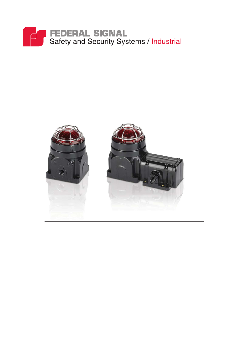
Global Series
Model G-LED LED Beacon
For Use in Hazardous Locations
Ex d Surface Mount Ex de Surface Mount
Installation and
25500186
Rev. B5 0918
Printed in U.S.A.
Maintenance Instructions
Page 2
Limited Warranty
This product is subject to and covered by a limited warranty,
a copy of which can be found at www.fedsig.com/SSG-Warranty.
A copy of this limited warranty can also be obtained by written
request to Federal Signal Corporation, 2645 Federal Signal Drive,
University Park, IL 60484, email to info@fedsig.com or
call +1 708-534-3400.
This limited warranty is in lieu of all other warranties, express or
implied, contractual or statutory, including, but not limited to the
warranty of merchantability, warranty of tness for a particular
purpose and any warranty against failure of its essential purpose.
2645 Federal Signal Drive
University Park, IL 60484-3167
www.fedsig.com
Customer Support: 1 800-344-4634 • 1 708-534-4756
Technical Support: 1 800-755-7621 • 1 708-587-3587
Page 3
Contents
Safety Messages to Installers and Users .......................................................... 5
Certication .......................................................................................................... 6
Unpacking the Beacon ....................................................................................... 7
Creating Combination Fixtures in the Field ...................................................... 8
Mounting the G-LED Beacon .............................................................................. 9
Mounting the Surface-Mount Ex d Beacon ................................................... 9
Mounting the Ex de Surface-Mount Beacon ............................................... 10
Safety Messages for Wiring .............................................................................. 13
Preparing to Wire the Ex d Flameproof Models .............................................. 14
Wiring the Ex d Models ..............................................................................15
24 Vdc Models ............................................................................................ 15
120-240 Vac Models .................................................................................... 15
Preparing to Wire the Ex de Increased Safety Models ................................... 16
Wiring the Ex de Models .............................................................................17
24 Vdc Models ............................................................................................ 18
120-240 Vac Models .................................................................................... 18
Changing the Flash Pattern .............................................................................. 19
Safety Messages to Maintenance Personnel .................................................. 22
Maintaining the Beacon .................................................................................... 23
Cleaning the Enclosure ................................................................................ 23
Replacing the LED Array ............................................................................ 23
Lubricating the Threaded Joints .................................................................. 25
Ordering Replacement Parts and Accessories ..............................................26
Getting Repair Service or Technical Assistance ............................................ 27
Returning the Product for Credit ..................................................................... 27
Model G-LED Global Series LED Beacon
3
Page 4

Contents
Tables
Table 1 Replacement parts .................................................................................26
Table 2 Accessories ............................................................................................27
Table 3 Choosing cable-entry devices for Equipment in
Potentially Explosive Atmospheres......................................................................29
Figures
Figure 1 Beacon and sounder combination xture ...............................................8
Figure 2 Front view of Ex d beacon ......................................................................9
Figure 3 Side view of Ex d beacon .....................................................................10
Figure 4 Front view of Ex de surface mount ....................................................... 11
Figure 5 Side view of Ex de surface mount ........................................................12
Figure 6 IN/OUT PCB connections for Ex d 24 Vdc ...........................................15
Figure 7 IN/OUT PCB connections for Ex d 120-240 Vac ..................................16
Figure 8 Connections for DC or AC Ex de beacons ..........................................18
Figure 9 Location of DIP switch for ash patterns ..............................................21
Figure 10 Switch settings for ash patterns ........................................................21
Figure 11 LED array and connector ....................................................................24
© 2017 Federal Signal Corporation. All rights reserved.
4
Model G-LED Global Series LED Beacon
Page 5
Installation and Maintenance Instructions
Safety Messages to Installers and Users
It is important to follow all instructions shipped with this product. This
beacon is to be installed by a trained electrician who is thoroughly familiar
with and will follow all applicable national and local codes in the country of
use.
This beacon should be considered a part of the warning system and not the
entire warning system.
The selection of the mounting location for the beacon, its controls and the
routing of the wiring are to be accomplished under the direction of the
facilities engineer and the safety engineer. In addition, listed below are some
other important safety instructions and precautions you should follow:
• Read and understand all instructions before installing or operating this
equipment.
• To avoid electrical shock hazards, do not connect wires when power is
applied. Failure to observe this warning may lead to serious injury or
death.
• Never alter the unit in any manner. Safety in hazardous locations may be
endangered if additional openings or other alterations are made in units
specically designed for use in these locations.
• Do not connect this beacon to the system when power is on.
• After installation, ensure that all threaded joints are properly tightened.
• Keep the unit tightly closed when in operation.
• After installation, test the beacon system to ensure that it is operating
properly.
• After testing is complete, provide a copy of this instruction sheet to all
personnel.
• Brass inserts have the potential to store charge when they are not
plugged. Consideration should be taken to prevent these from becoming
a sparking hazard.
Model G-LED Global Series LED Beacon
5
Page 6
Installation and Maintenance Instructions
• The lens guard has the potential to store charge. Consideration should be
taken to prevent this from becoming a sparking hazard.
• Establish a procedure to routinely check the beacon system for proper
activation and operation.
• Maximum ash frequency is 90 FPM.
• This equipment is suitable for use in Class I, Division 2, Groups A, B,
C, D; Class II, Division 2, Groups F and G; Class III or non-hazardous
locations only.
• WARNING: EXPLOSION HAZARD — Do not disconnect the
equipment unless power has been switched off or unless the area is
known to be non-hazardous.
• WARNING: EXPLOSION HAZARD — Do not remove or replace the
fuse when energized.
Failure to follow all safety precautions and instructions may result in
property damage, serious injury, or death.
With respect to the potential electrostatic charging hazard as mentioned in the
certicate “Specic Conditions of Use”, under normal conditions of use, these
devices are for xed installations and not generally in contact with people.
The risk of ignition is low. In addition, maintenance, cleaning, and extreme
environmental factors (ex. high velocity dust laden atmospheres or high pressure
steam) should be taken into account by the end user, using local Explosive
Atmosphere (Ex) Electrical installations design, selection, inspection, and
maintenance Codes and Standards. Cleaning of the devices should only be done
with a damp cloth.
Certication
Certicate Nos.: ATEX Cert No.: Baseefa15ATEX0153X
IECEx Cert No.: IECEx BAS 15.0102X
ATEX coding: II 2 G D
Protection: II 2 GD Ex db op is IIC T6 Gb or II 2 GD Ex db e op is IIC T6 Gb
Ex op is tb IIIC T85°C Db IP66 (Tamb= -50°C to + 58°C)
II 2 GD Ex db op is IIC T5 Gb or II 2 GD Ex db e op is IIC T5 Gb
Ex op is tb IIIC T100°C Db IP66 (Tamb= -50°C to + 70°C)
Standards:
EN60079-31:2014, IEC60079-0: 6th Ed.,
IEC 60079-1 7th Ed.,
IEC 60079-7: 4th Ed., IEC60079-31: 2st Ed,
IEC 60079-28:2006
6
E
N60079-0: 2012 + A11:2013,
E
N60079-7: 2007,
EN60079-28: 2007,
EN60079-1:2014
Model G-LED Global Series LED Beacon
Page 7
Installation and Maintenance Instructions
Specic Conditions of Use:
1. The Modular Visual LED has external non-metallic surfaces which may
provided a potential electrostatic charging hazard.
See the manufacturer’s instructions for further information.
2. The Modular Visual LED has metallic components in the non-metallic
walls of the enclosure which can store electrical charge and therefore
may provide a potential electrostatic charging hazard. The metallic
brass inserts have a capacitance of 14 pF. The metallic guard has a
capacitance of 18 pF. See the manufacturer’s instructions for further
information.
cULus Zone Certications:
Models that contain the Ex e increased safety (E-box) are not cULus Zone
certied and not suitable for use in Class, Zone locations. Only the following
models are certied: G-LED-DC-D-x, G-LED-DC-T-x, G-LED-AC-D-x,
and G-LED-AC-T-x. Please disregard any references to the E-box when
using these instructions for Class, Zone locations.
These models use protections:
Class I, Zone 1, AEx db IIC T3
Zone 21, AEx tb IIIC T3/200°C IP66 (Tamb= -55°C to +70°C)
Ex db IIC T3
Ex tb IIIC T3/200°C IP66 (Tamb= -55°C to +70°C)
Unpacking the Beacon
EXPLOSION HAZARD: A damaged lens can lead to explosions, causing
serious injury or death. If a lens is damaged, it must be replaced.
After unpacking the beacon, examine it for damage that may have occurred
in transit. If it has been damaged, do not attempt to install or operate it.
File a claim immediately with the carrier, stating the extent of the damage.
Carefully check all envelopes, shipping labels, and tags before removing
or discarding them. Disposal of all shipping materials must be carried out
in accordance with national and local codes and standards. If any parts are
missing, please call Federal Signal Customer Support at +1 708-534-4756 or
+1 877-289-3246.
Model G-LED Global Series LED Beacon
7
Page 8
Installation and Maintenance Instructions
Creating Combination Fixtures in the Field
The Federal Signal Global Series Ex de products can be connected together
in the eld using interchangeable E-box end caps and a proprietary coupling
system. The proprietary coupling system allows for simple and cost
effective, wiring from product to product, often eliminating the need for
expensive Ex wiring practices and Ex rated glands.
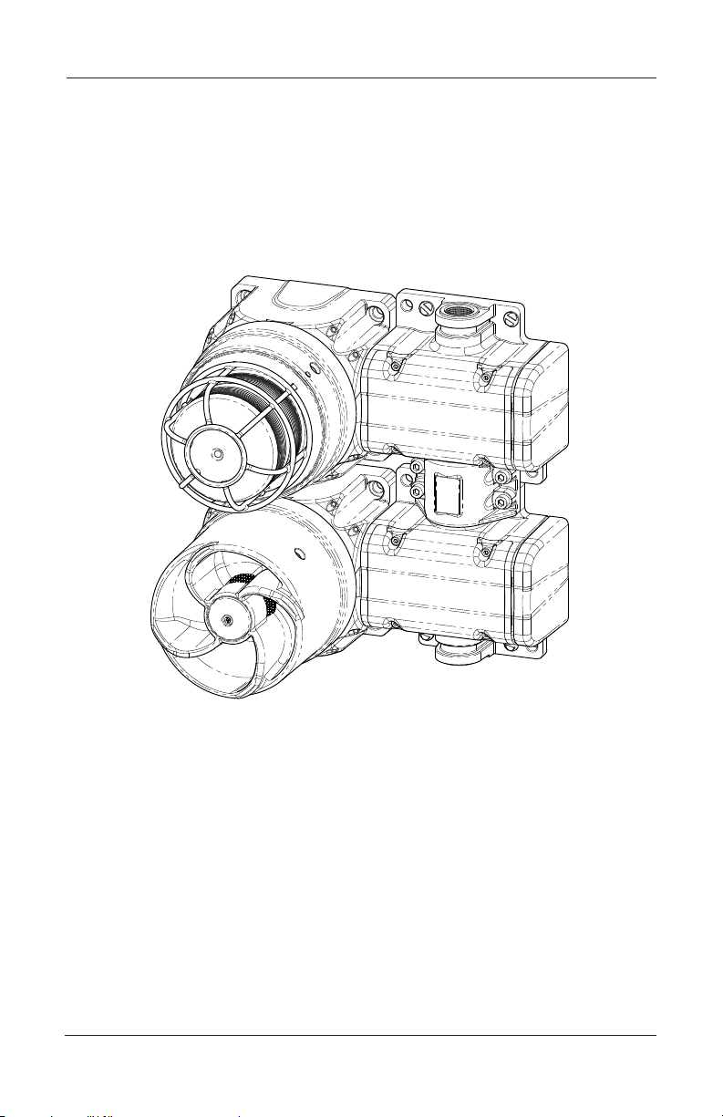
Figure 1 Beacon and sounder combination xture
The E-box is available only when factory installed on an Ex d unit or when
used as a E-box spacer adjoining an existing E-box. Refer to the accessories
listed on page 26 for available options. When creating certain xture
combinations, it is necessary to replace the E-box end caps before mounting
the product. If you are creating combination xtures, refer to instruction
manual 25500259 for specic instructions and details.
A note about combination xtures: If the product is Ex db marked, it is for
use in gas atmospheres. If the product is Ex db e marked, it uses increasedsafety terminal enclosures and is for use in gas atmospheres. The product is
Ex tb marked for use in dust atmospheres.
8
Model G-LED Global Series LED Beacon
Page 9
Installation and Maintenance Instructions
105.9 mm (4.17 in)
Mounting the G-LED Beacon
ATTACH THE BEACON SECURELY: To prevent injury, this apparatus
must be securely attached to the mounting surface in accordance with
the installation instructions. Use installer-supplied fasteners suitable for
the mounting surface.
The mounting method and the installer-supplied mounting hardware depend
on which of the two G-LED models you are installing:
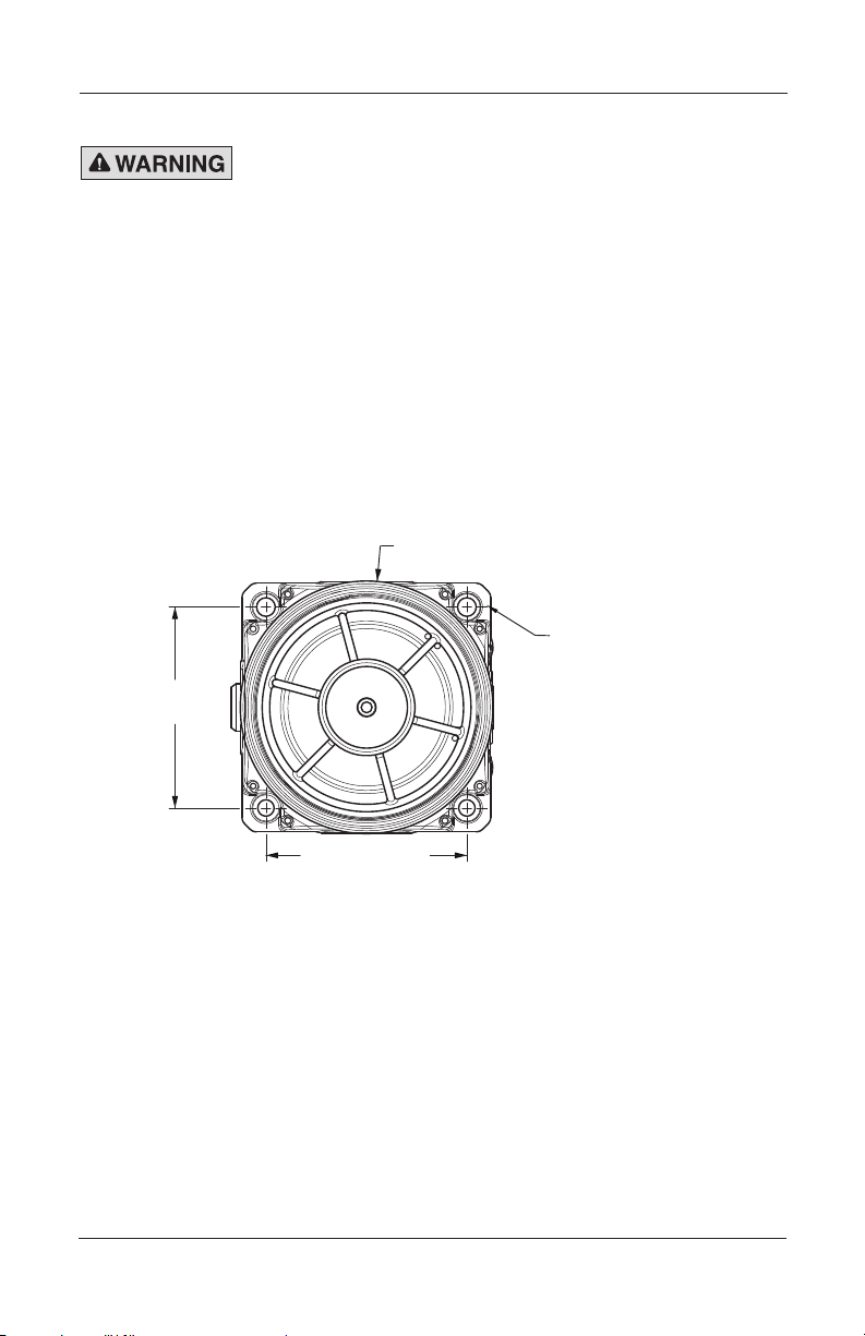
Mounting the Surface-Mount Ex d Beacon
Mount the beacon to a at surface using the four 8.5 mm mounting
holes. Use installer-supplied fasteners suitable for the surface to which
the device will be mounted.
Figure 2 Front view of Ex d beacon
Ø105.9 mm (5.27 in)
4X COUNTER-BORED
HOLES TO FIT M8
SOCKET-HEAD
105.9 mm
(4.17 in)
CAP SCREWS
Model G-LED Global Series LED Beacon
9
Page 10

Installation and Maintenance Instructions
190.6 mm (7.50 in)
Figure 3 Side view of Ex d beacon
132.6 mm
(5.22 in)
2X M20 GLAND ENTRIES
34.9 mm
(1.38 in)
Mounting the Ex de Surface-Mount Beacon
Mount the beacon to a at surface using the six 8.5 mm mounting holes.
Use installer-supplied fasteners suitable for the surface to which the
device will be mounted.
10
Model G-LED Global Series LED Beacon
Page 11

4X COUNTER-BORED
105.9 mm
(4.17 in)
Installation and Maintenance Instructions
Figure 4 Front view of Ex de surface mount
HOLES TO FIT M8
SOCKET-HEAD
CAP SCREWS
23.2 mm
(0.91 in)
2X Ø8.5 mm
3X M20
GLAND
ENTRIES
103.2 mm
(4.06 in)
122.6 mm
(4.83 in)
Model G-LED Global Series LED Beacon
11
Page 12

Installation and Maintenance Instructions
Figure 5 Side view of Ex de surface mount
227.4 mm
(8.95 in)
272.0 mm
(10.71 in)
3X M20 GLAND ENTRIES
REPLACEABLE E-BOX END CAPS
12
SEE ACCESSORIES FOR
Model G-LED Global Series LED Beacon
Page 13

Installation and Maintenance Instructions
Safety Messages for Wiring
When installing and operating ame-proof electrical equipment, the relevant
national regulations for installation and operation (e.g., EN60079-14, IEC
Wiring Regulations and NEC/CEC) must be observed.
• To maintain the ame-proof integrity of the enclosure, DO NOT damage
the LED lens cover or threads while disassembling or reassembling unit.
• To avoid electrical shock hazards, do not connect wires when power is
applied. Failure to observe this warning may lead to serious injury or
death.
• Painting and surface nishes, other than those applied by Federal Signal
Corporation, are not permitted.
• Cable termination should be in accordance with specications applying
to the application. Federal Signal recommends that all cables and cores
should be fully identied.
• Ensure that only the correct equipment-certied glands are used and
that the assembly is shrouded and correctly earthed. Gland entries
are M20-1.5 6H with an option for the M25 entry on the end of the
increased safety box models. See Table 3 on page 28 for choosing
the correct cable entry devices for Equipment in Potentially Explosive
Atmospheres.
• Because of space limitations, ensure the cable cores within the unit are
not too slack.
• In all countries, the wiring must comply with all national and local codes
and standards.
• Ensure that all nuts, bolts, and xings are secure.
Model G-LED Global Series LED Beacon
13
Page 14

Installation and Maintenance Instructions
Preparing to Wire the Ex d Flameproof Models
SHOCK HAZARD: To avoid electrical shock hazards, do not connect
wires when power is applied. Failure to observe this warning may lead to
serious injury or death.
CIRCUIT BOARD DAMAGE: The DC beacons are polarity sensitive, and
MAY BE DAMAGED by incorrect electrical hookup. When connecting the
DC beacon to the voltage supply lines, POLARITY MUST BE OBSERVED.
In addition, damage will result if the voltage rating of the particular
model is exceeded by more than 10 percent.
This section has wiring instructions for the two ameproof models:
• G-LED 24 Vdc
• G-LED 120-240 Vac
Ex d units are supplied with a six position PCB mounted screw terminal
block. The maximum wire gauge is 4 mm2 (12 AWG). The wire must be rated
85 °C or higher. Use only stranded cable to terminate the beacon. The cross-
sectional area of the primary earth (ground) must equal the cross-sectional
area of the phase conductor.
Cable termination for these models should be in accordance with
specications applying to the application. It is recommended that all cables
and cores should be fully identied. Use the appropriate cable gland for the
application. Gland entry threads are M20-1.5 x 6H.
Tools needed:
• 1.5 mm A/F hexagon key
• 2 mm at-tip screwdriver
• No. 1 Phillips screwdriver
• Wire stripper
14
Model G-LED Global Series LED Beacon
Page 15

Installation and Maintenance Instructions
J1
GND GND
+ - + -
Wiring the Ex d Models
To wire the Ex ameproof beacon:
1. Unscrew the M3 hex set screw on the side of the housing one
full turn.
2. Remove the lens cover from the housing by turning the cover
counter-clockwise. Three 120-degree spaced reliefs are provided
for a 3/8 in spanner wrench if needed. If the cover will not
unscrew, back out the set screw a few additional turns.
3. Loosen the captive Phillips screw retaining the printed circuit
board (PCB).
4. Slide out the PCB until the terminals clear the housing. Strip the
wire insulation 8 mm (0.31 in). Maximum screw tightening torque
is 0.6 Nm (5 in-lb).
24 Vdc Models
a. See Figure 6. Connect the positive (+) power source wire to the
terminal-block screw marked +.
b. Connect the negative (▬) power source wire to the terminal block
screw marked ▬.
c. Connect the earth ground wire to the terminal block pole marked
120-240 Vac Models
To wire the Ex d Vac ameproof beacon:
a. See Figure 7 on page 16. Connect the line (hot) power source
-GND
Figure 6 IN/OUT PCB connections for Ex d 24 Vdc
wire to the terminal block screw marked L1 on the PCB.
Model G-LED Global Series LED Beacon
15
Page 16

Installation and Maintenance Instructions
J1
GND GND
L1 L2 L2L1
Figure 7 IN/OUT PCB connections for Ex d 120-240 Vac
b. Connect the neutral (common) power source wire to the terminal
block screw marked L2.
c. Connect the ground wire to the terminal block clamp marked GND.
5. Insert the PCB into the enclosure and fully tighten the PCB captive
screw.
6. Place the cover on the housing and tighten it by turning it clockwise.
7. To ensure O-ring compression, the cover must be fully seated against
the housing when the threads are tightened. Turn the M3 set screw on
the side of the housing until the screw contacts the housing.
8. Ensure that the unused wire entries are sealed with the provided brass
M20-1.5 x 6 g stopping plug (equipment-certied).
9. Test the beacon for proper operation.
Preparing to Wire the Ex de Increased Safety Models
SHOCK HAZARD: To avoid electrical shock hazards, do not connect
wires when power is applied. Failure to observe this warning may lead to
serious injury or death.
This section has wiring instructions for the two increased safety models:
• G-LED 24 Vdc
• G-LED 120-240 Vac
Ex de units are supplied with a six-pole spring tension clamp style terminal
block. The maximum wire gauge is 4.0 mm2 (12 AWG). The wire must be
rated 85 °C or higher. Use only stranded cable to terminate the beacon.
cross-sectional area of the primary earth (ground) must equal the crosssectional area of the phase conductor.
16
Model G-LED Global Series LED Beacon
The
Page 17

Installation and Maintenance Instructions
Cable termination should be in accordance with specications applying to
the application. It is recommended that all cables and cores should be fully
identied. Use the appropriate cable gland for the application. Gland entry
threads are M20-1.5 6H.
Conductive metalwork, including cable glands, must be a minimum of 5 mm
away from the terminals.
Leads connected to the terminals shall be insulated for the appropriate
voltage and this insulation shall extend to within 1 mm of the metal of the
terminal throat.
The G-LED terminal block is supplied with two conductors per pole. The
terminal block allows for easy supply-in and loop-out wiring to connect
beacons in series.
Tools needed:
• 3.0 mm hexagon key
• No. 1 Phillips screwdriver
• Wire stripper
Wiring the Ex de Models
CIRCUIT BOARD DAMAGE: The DC beacons are polarity sensitive,
and MAY BE DAMAGED by incorrect electrical hookup. When
connecting the DC beacon to the voltage supply lines, POLARITY
MUST BE OBSERVED. In addition, damage will result if the voltage
rating of the particular model is exceeded by more than 10 percent.
To wire the Ex de beacon:
1. Unscrew the four M4 socket-head cap screws and remove the
terminal box cover.
2. Strip the wire insulation 8 mm to 9 mm (0.33 in).
NOTE: When using more than one single or multiple strand lead, the
connection into either side of any terminal must be joined in a suitable
manner, e.g. two conductors into a single insulated crimped bootlace
ferrule.
3. To connect wires, depress the pushbutton on the terminal block
with a Phillips screwdriver and insert the wire into the round
opening. Release the pushbutton to make connection.
Model G-LED Global Series LED Beacon
17
Page 18

Installation and Maintenance Instructions
24 Vdc Models
a. See Figure 8. Connect the positive (+) power source wire to the
terminal block pole marked L1/+.
b. Connect the negative (▬) power source wire to the terminal block
pole marked L2/-.
Figure 8 Connections for DC or AC Ex de beacons
Aud+L1/+ L2/-
L3/Alt+
A A
Aud-
Aud+L1/+ L2/- L3/Alt+ Aud-
c. Connect the earth ground wire to the terminal block pole marked
.
120-240 Vac Models
a. See Figure 8. Connect the line (hot) power source wire to the
terminal block screw marked L1/+.
b. Connect the neutral (common) power source wire to the terminal
block pole marked L2/-.
c. Connect the earth ground wire to the terminal block pole marked
.
4. Secure the cover on the terminal box with the four M4 screws. Ensure
that the gasket is properly seated to maintain the IP rating. Do not
overtighten the cover screws.
5. Test the beacon for proper operation.
18
Model G-LED Global Series LED Beacon
Page 19

Installation and Maintenance Instructions
Changing the Flash Pattern
LIGHT HAZARD: To be an effective warning device, the beacon produces
bright light that can be hazardous to your eyesight when viewed at close
range. Do not stare directly into the light at close range or permanent
damage to your eyesight may occur.
EXPLOSION HAZARD: To prevent ignition of hazardous atmosphere,
disconnect the device from the supply circuit before opening it. Do not
open the device in the presence of explosive gases in the atmosphere.
BURN HAZARD: The LED emitter gets hot enough to burn you. Always
allow the emitter to cool before handling it.
The Model G-LED Series beacon has eight ash patterns that are selected by
setting a DIP switch on the PCB. See Figures 9 and 10 on page 20.
Tools needed:
• 1.5 mm A/F hexagon key
• 2 mm blade-tip screwdriver
• No. 1 Phillips screwdriver
To select a pattern:
1. Disconnect power to the beacon.
2. Unscrew the M3 set screw on the side of the housing one full turn.
3. Remove the lens cover from the housing by turning the cover counter-
clockwise. Three 120-degree spaced reliefs are provided for a spanner
wrench if needed. If the cover assembly will not unscrew, back out the
set screw a few additional turns
4. Loosen the captive Phillips screw retaining the printed circuit board
(PCB), and slide out the PCB until DIP switch SW1 is accessible.
5. Select a ash pattern by setting the DIP switches on SW1. Steady On is
the default.
6. Insert the PCB assembly into the enclosure and fully tighten the captive
screw.
Model G-LED Global Series LED Beacon
19
Page 20

Installation and Maintenance Instructions
7. Place the cover on the housing and tighten it by turning it clockwise. To
ensure O-ring compression, the cover must be fully seated against the
housing when the threads are tightened.
8. Turn the M3 set screw against the housing until the screw contacts the
housing.
9. Reconnect power to the beacon.
10. Test the beacon by applying power and verifying the pattern.
Figure 9 Location of DIP switch for ash patterns
STEADY ON (DEFAULT)
20
Model G-LED Global Series LED Beacon
Page 21

Installation and Maintenance Instructions
Figure 10 Switch settings for ash patterns
ON
Steady On
1 2 3
ON
Blink (60 SPM)
1 2 3
ON
Swell (60 SPM)
1 2 3
ON
Strobe Simulation
1 2 3
ON
Rotate
Counterclockwise
1 2 3
ON
Rotate Clockwise
1 2 3
ON
Waggle
1 2 3
ON
Pinwheel
1 2 3
Safety Messages to Maintenance Personnel
Listed below are some important safety instructions and precautions you
should follow:
• Read and understand all instructions before operating this system.
• If you acquired a signicant quantity of units, then it is recommended
that spares are also made available.
• Any maintenance to the beacon system must be done with power
turned off.
• Any maintenance to the beacon system must be performed by a trained
electrician who is thoroughly familiar with all applicable national and
local codes in the country of use.
• To avoid electrical shock hazards, do not connect wires when power is
applied. Failure to observe this warning may lead to serious injury or
death.
Model G-LED Global Series LED Beacon
21
Page 22

Installation and Maintenance Instructions
• Never alter the unit in any manner. Safety of the unit may be affected
if additional openings or other alterations are made to the internal
components or housing.
• Repair of amepaths is not intended.
• The nameplate, which may contain cautionary or other information of
importance to maintenance personnel, should NOT be obscured in any
way. Ensure that the nameplate remains readable.
• After performing any maintenance, test the beacon system to ensure that
it is operating properly.
Failure to follow all safety precautions and instructions may result in
property damage, serious injury, or death.
Maintaining the Beacon
EXPLOSION HAZARD: To prevent ignition of hazardous atmosphere,
disconnect the beacon from the supply circuit before opening it. Do not
open the beacon in the presence of explosive gases in the atmosphere.
Failure to follow this warning may result in serious injury or death.
During the working life of the beacon, it should require little or no
maintenance. The non-metallic housing will resist attack by most acids,
alkalis, and chemicals and is as resistant to concentrated acids and alkalis
as most metal products. However, if abnormal or unusual environment
conditions occur due to plant damage or accident, etc., visual inspection of
the beacon is recommended.
Cleaning the Enclosure
The enclosure should be cleaned periodically with a damp cloth to
maintain maximum light output. The polycarbonate colored LED lens
should be regularly inspected for cracks. If it is damaged, it must be
replaced. Refer to the “Certication” section on page 6 for any
applicable Specic Conditions of Use.
Replacing the LED Array
EXPLOSION HAZARD: To maintain the ameproof integrity of
the enclosure, DO NOT damage the lens cover, or threads while
disassembling or reassembling the beacon.
22
Model G-LED Global Series LED Beacon
Page 23

Installation and Maintenance Instructions
J1 CONNECTOR
LIGHT HAZARD: To be an effective warning device, the beacon
produces bright light that can be hazardous to your eyesight when
viewed at close range. Do not stare directly into the beacon at close
range or permanent damage to your eyesight may occur.
Federal Signal LED array part No. K859500823-*
BURN HAZARD: The LED array gets hot enough to burn you. Always
allow the array to cool before handling it.
STATIC SENSITIVE DEVICE: The circuitry of the beacon can be
damaged by an electrostatic discharge (ESD). Always follow antistatic procedures while servicing the beacon.
Tools and replacement part needed:
• 1.5 mm A/F hexagon key
• No. 1 Phillips screwdriver
• Federal Signal LED array part no. K859500823-*.
Figure 11 LED array and connector
LED ARRAY
Model G-LED Global Series LED Beacon
23
Page 24

Installation and Maintenance Instructions
Remove the LED Array:
1. Disconnect power to the beacon.
2. Use the hexagon key to unscrew the set screw on the housing one
full turn.
3. Remove the cover from the housing by turning the cover counter-
clockwise. If the cover will not unscrew, back out the set screw a
few additional turns.
4. Loosen the captive Phillips screw retaining the printed circuit
board (PCB) and slide the PCB out of the housing,
5. See Figure 11 on page 23. Unplug the J1 connector and remove
the three Phillips screws retaining the LED array to the mounting
bracket.
6. Remove the LED array.
Install the new the LED Array:
1. Secure the new LED array to the mounting bracket with the three
Phillips screws.
2. Reconnect J1 and slide the PCB back into the housing.
3. Tighten the captive Phillips retaining screw.
4. Place the cover on the housing and tighten it by turning it
clockwise.
5. To ensure O-ring compression, the cover must be fully seated
against the housing when the threads are tightened. Turn the M3
set screw on the side of the housing until the screw contacts the
housing.
6. Reconnect power to the beacon.
7. Apply power and verify that the beacon operates properly.
Lubricating the Threaded Joints
A silicone based, non-hardening, chemically compatible grease can be
applied if required.
24
Model G-LED Global Series LED Beacon
Page 25

Installation and Maintenance Instructions
Ordering Replacement Parts and Accessories
EXPLOSION HAZARD: A damaged lens can lead to explosions, causing
serious injury or death. If a lens is damaged, it must be replaced.
Replacement parts and accessories are listed in Table 1 below and 2 on
page 26. Due to certication, certain component parts are not available for
eld replacement. Beacons with this type of damage must be either replaced
entirely or returned to Federal Signal for service.
Refer to instruction manual 25500259 for accessory and replacement part
assembly and operating instructions.
To order, call Federal Signal Customer Support at 708-534-4756 or
877-289-3246.
Table 1 G-LED Replacement Parts
Description Part Number
Lens Guard K859500821-02
Lens, Amber K859500815
Lens, Blue K859500815-01
Lens, Clear K859500815-02
Lens, Green K859500815-03
Lens, Red K859500815-04
Lens, Magenta K859500815-05
Lens, Yellow K859500815-06
DC LED (24VDC) Internal Sub-Assembly Kits (Include PCBA, bracket,
LED light head and mounting screw)
LED/PCB DC Sub-Assy, Amber K859501400-A
LED/PCB DC Sub-Assy, Blue K859501400-B
LED/PCB DC Sub-Assy, White K859501400-W
LED/PCB DC Sub-Assy, Green K859501400-G
LED/PCB DC Sub-Assy, Magenta K859501400-W
LED/PCB DC Sub-Assy, Red K859501400-R
LED/PCB DC Sub-Assy, Yellow K859501400-W
Model G-LED Global Series LED Beacon
25
Page 26

Installation and Maintenance Instructions
G-LED Replacement Parts con’t.
AC LED (120-240VAC) Internal Sub-Assembly Kit Includes PCBAs,
bracket, LED light head and mounting screw)
LED/PCB AC Sub-Assy, Amber K859501401-A
LED/PCB AC Sub-Assy, Blue K859501401-B
LED/PCB AC Sub-Assy, White K859501401-W
LED/PCB AC Sub-Assy, Green K859501401-G
LED/PCB AC Sub-Assy, Magenta K859501401-W
LED/PCB AC Sub-Assy, Red K859501401-R
LED/PCB AC Sub-Assy, Yellow K859501401-W
Table 2 Accessories
Description Part Number
Indicator Ring/Legend Kit, Black G-KIT-RP-BK
Indicator Ring/Legend Kit, Blue G-KIT-RP-B
Indicator Ring/Legend Kit, Green G-KIT-RP-G
Indicator Ring/Legend Kit, Magenta G-KIT-RP-M
Indicator Ring/Legend Kit, Red G-KIT-RP-R
Indicator Ring/Legend Kit, Yellow G-KIT-RP-Y
E-Box Endcap with M20 Opening K859500805-02
E-Box Endcap with M25 Opening K859500805-01
E-Box Cover Assembly (Includes two terminal
K859501414
blocks, mounting plate, retention hardware)
In-Line E-Box Coupler Kit G-KIT-EC180
90-Degree E-Box Coupler Kit G-KIT-EC90
Extension Box Spacer Kit G-KIT-EXTB
Single Trunnion Kit G-KIT-ST
Dual Trunnion Kit G-KIT-DT
Adapter, M20 Male to 1/2” Female NPT K231246A
Adapter, M20 Male to 3/4” Female NPT K231247
26
Model G-LED Global Series LED Beacon
Page 27

Installation and Maintenance Instructions
Getting Repair Service or Technical Assistance
Products returned for repair require a Return Authorization form from your
local distributor or from Federal Signal. To obtain repair service or technical
assistance from Federal Signal, call 708-534-4756 or 877-289-3246.
For instruction manuals and information on related products,
visit: http://www.federalsignal-indust.com.
Returning the Product for Credit
Product returns for credit require a return authorization from your local
distributor prior to returning the product to Federal Signal. Please contact
your distributor for assistance.
A product is qualied to be returned for credit when the following conditions
are met:
• The product is resalable and in the original cartons.
• The product has not been previously installed.
• The product is the current revision.
• The product has not been previously repaired.
• The product is a standard product.
• The product is not a service part.
All returns are subject to a re-stock fee.
Defective products that are returned within the warranty period will be
repaired or replaced at Federal Signal’s sole discretion. Defective products
do not include those products with lamp failure.
Circumstances other than those listed above will be addressed on a case-bycase basis.
Model G-LED Global Series LED Beacon
27
Page 28

Installation and Maintenance Instructions
Table 3 Choosing cable-entry devices for Equipment in
Potentially Explosive Atmospheres
Models Ex Atmospheres
G-LED-XXX-D-X
(Ex db surface
mount)
G-LED-XXX-E-X
(Ex db surface
mount)
G-LED-XXX-D-X
(Ex db surface
mount)
G-LED-XXX-E-X
(Ex db e surface
mount)
Gas Cable entry devices shall be
Gas For the ameproof beacon
Dust Cable entry devices for the
Cable Entry Devices (cable
glands, stopping plugs, etc.
equipment certied as ameproof.
To maintain the ingress protection
of the ameproof beacon
enclosure, we recommend
the cable entry device be
IP66 certied.
enclosure, cable entry devices
shall be equipment certied
as ameproof. To maintain
the ingress protection of the
ameproof beacon enclosure
we recommend the cable entry
device be IP66 certied. For
the increased safety terminal
enclosures (terminal boxes), cable
entry devices shall be equipment
certied as increased safety and
shall maintain an IP rating of IP54.
Beacon and terminal enclosures
shall be equipment certied as
dust protected. To maintain the
ingress protection of the beacon
and terminal enclosures the
cable entry devices shall be
IP6X certied.
28
Model G-LED Global Series LED Beacon
Page 29

Installation and Maintenance Instructions
2645 Federal Signal Drive
University Park, IL 60484-3167
www.fedsig.com
Customer Support: 1 800-344-4634 • 1 708-534-4756
Technical Support: 1 800-755-7621 • 1 708-587-3587
Model G-LED Global Series LED Beacon
29
 Loading...