

Federal Signal Corporation Commander 371LED-120 Installation And Maintenance Manual
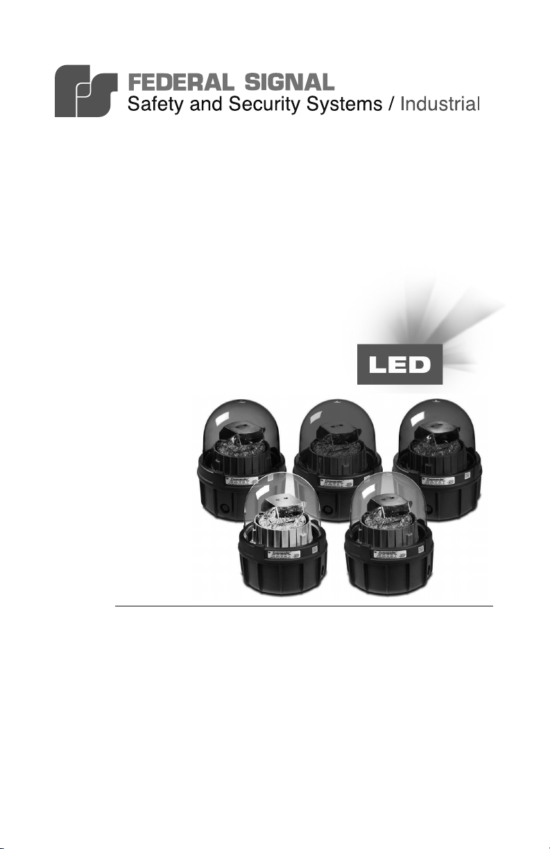
Commander® Rotating Light
Model 371LED-120
2562671A
REV. A1 0714
Printed in U.S.A.
Installation and
Maintenance Manual
français...............page 17
español...............página 33
Warranty – Seller warrants all goods for ve years on parts and 2-1/2 years
on labor, under the following conditions and exceptions: Seller warrants that
all goods of Seller's manufacture will conform to any descriptions thereof
for specications which are expressly made a part of this sales contract and
at the time of sale by Seller such goods shall be commercially free from
defects in material or workmanship. Seller reserves the right at the Seller’s
discretion to “Repair and Return” or “Replace” any item deemed defective
during the warranty period. This warranty does not cover travel expenses,
the cost of specialized equipment for gaining access to the product, or labor
charges for removal and reinstallation of the product. This warranty shall be
ineffective and shall not apply to goods that have been subjected to misuse,
neglect, accident, damage, improper maintenance, or to goods altered or
repaired by anyone other than Seller or its authorized representative, or if
ve years have elapsed from the date of shipment of the goods by Seller with
the following exceptions: lamps and strobe tubes are not covered under this
warranty. Outdoor warning sirens and controllers manufactured by Federal
Warning Systems are warranteed for two years on parts and one year on labor.
No agent, employee, representative or distributor of Seller has any authority
to bind the Seller to any representation, afrmation, or warranty concerning
the goods and any such representation, afrmation or warranty shall not be
deemed to have become a part of the basics of the sales contract and shall
be unenforceable. THE FOREGOING WARRANTIES ARE EXCLUSIVE
AND IN LIEU OF ALL OTHER WARRANTIES OR MERCHANTABILITY,
FITNESS FOR PURPOSE AND OF ANY OTHER TYPE, WHETHER
EXPRESS OR IMPLIED. These warranties shall not apply unless Seller
shall be given reasonable opportunity to investigate all claims for allegedly
defective goods. Upon Seller's instruction a sample only of allegedly defective
goods shall be returned to Seller for its inspection and approval. The basis of
all claims for alleged defects in the goods not discoverable upon reasonable
inspection thereof pursuant to paragraph 8 hereof must be fully explained
in writing and received by Seller within thirty days after Buyer learns of the
defect or such claim shall be deemed waived.
Industrial Systems
2645 Federal Signal Drive • University Park, IL 60484-3167
Tel: 708-534-4756 • Fax: 708-534-4852
Email: elp@federalsignal.com • www.federalsignal-indust.com
Model 371LED-120 Rotating Light
Contents
Safety Messages to Installers ..........................................................5
An Overview of the Model 371LED-120 ........................................... 6
Unpacking the Light .......................................................................... 6
Mounting the Light ............................................................................8
Pipe Mounting the Light .......................................................... 8
Surface Mounting the Light
Installing the Optional 22.5-Degree Reector ................................. 9
Wiring the Light ............................................................................... 11
Safety Messages to Maintenance Personnel ................................ 13
Maintaining the Model 371LED-120 ...............................................13
Getting Service, Assistance, and Parts ......................................... 14
.....................................................9
Repair Service ....................................................................... 14
Technical Assistance
Accessories and Replacement Parts
Returning the Product for Credit ...................................................16
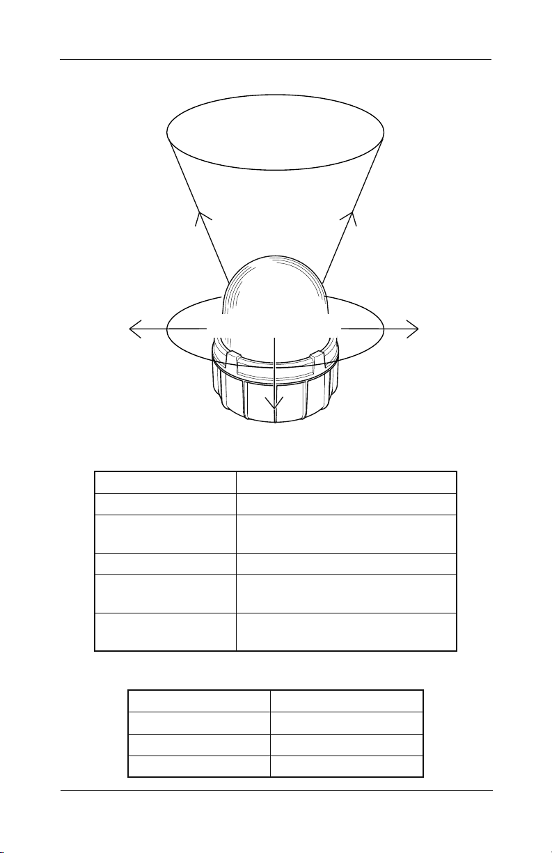
Figure 1 Beam with 22.5- and 90-degree reectors .........................7
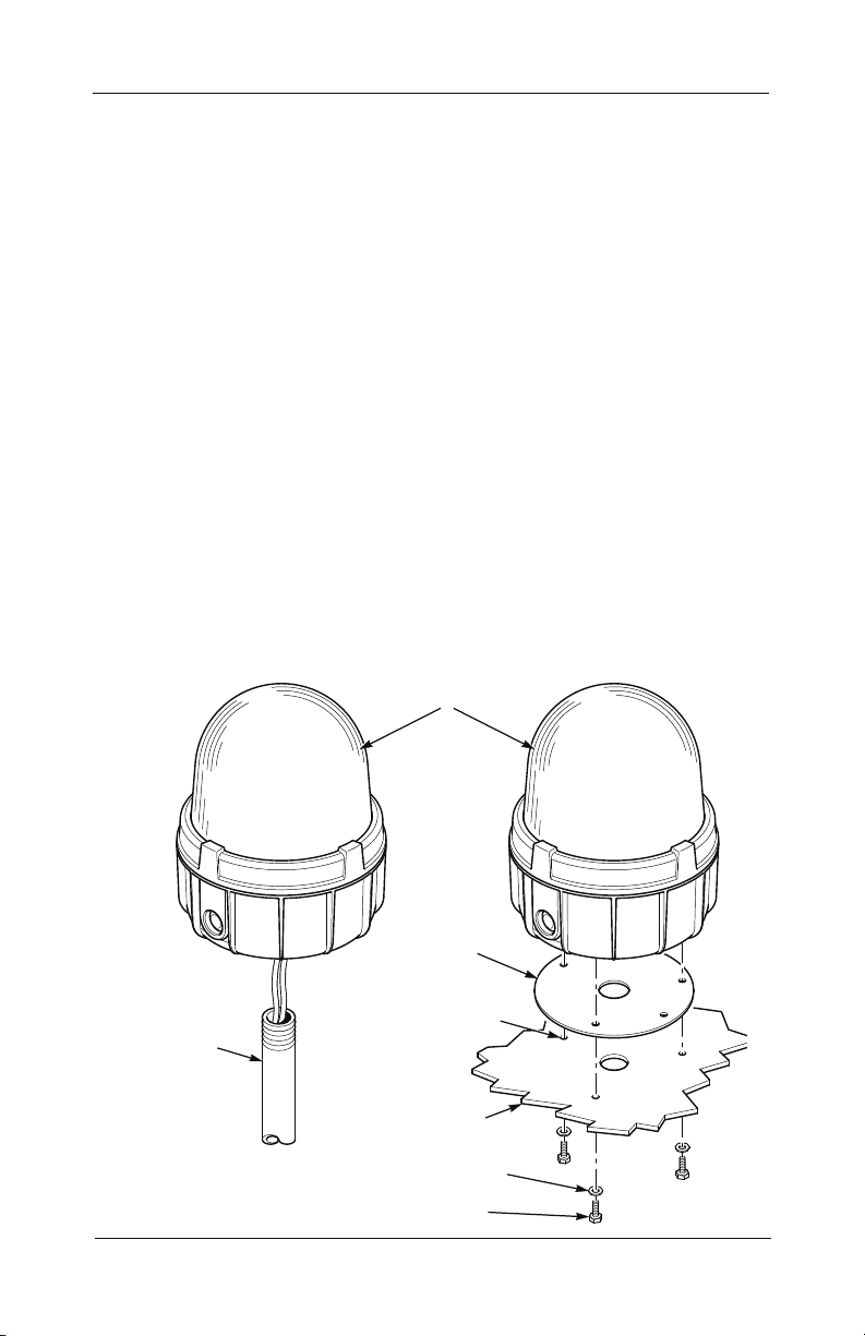
Figure 2 Mounting options ................................................................8
............................................................... 14
....................................... 14
Figures
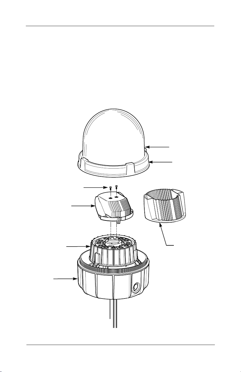
Figure 3 Installing the 22.5-degree reector ....................................10
Figure 4 Connecting leads to the terminal block ............................. 12
3
Model 371LED-120 Rotating Light
Contents
Tables
Table 1 Electrical and environmental ratings .....................................7
Table 2 Dimensions ............................................................................ 7
Table 4 Replacement parts .............................................................. 15
Table 5 Accessories ......................................................................... 15
4
Installation and Maintenance Instructions
Safety Messages to Installers
It is important to follow all instructions shipped with this product.
This device is to be installed by a trained electrician who is
thoroughly familiar with the National Electrical Code and/or
Canadian Electrical Code and will follow the NEC and/or CEC
Guidelines as well as all local codes. This light should be considered
a part of the warning system and not the entire warning system.
The selection of the mounting location for the light, its controls
and the routing of the wiring are to be accomplished under the
direction of the facilities engineer and the safety engineer. In
addition, listed below are some other important safety instructions
and precautions you should follow:
• Read and understand all instructions before installing or
operating this light.
• Do not connect this light to the system when power is on.
• After installation, make sure that all set screws and threaded
joints are properly tightened.
• To be an effective warning device, this product produces bright
light that can be hazardous to your eyesight when viewed at a
close range. Do not stare directly into this lighting product at a
close range or permanent damage to your eyesight may occur.
• After installation, test the light to make sure that it is
operating properly.
• After testing is complete; provide a copy of this instruction
booklet to all personnel.
• Establish a procedure to routinely check the light for proper
activation and operation.
Failure to follow all safety precautions and instructions may result
in property damage, serious injury, or death.
Model 371LED-120 Rotating Light
5

Installation and Maintenance Instructions
An Overview of the Model 371LED-120
Federal Signal Model 371LED-120 warning light incorporates
an array of high power LEDs, a custom optic, and a rotating
reector to focus a beam of light that rotates 360 degrees within
|a plastic dome.
The Model 371LED-120 features a impact-resistant plastic dome.
The Model 371LED is available in ve colors: amber, blue, clear,
green, and red. The dome-and-ring assembly screws on, providing
access to the interior of the light. The base features textured black
powder paint for greater corrosion-resistance. Wiring can be routed
through the pipe-mount opening in the bottom of the light or the
two side knockouts can be used for side entry wiring. Installation
can be surface or 1-inch NPT pipe mount.
An optional reector is available that reects the light beam at
22.5 degrees from the vertical orientation for overhead mounting
and other applications. See Figure 1 on page 7.
Also available is an optional wall-mount bracket. The LHWB
wall-mount bracket can be used to mount the Model 371LED. For
surface mounting on solid substrates, the separately purchased
Model 371BRCKT three-point surface-mount bracket is available.
Unpacking the Light
After unpacking the light, examine it for damage that may
have occurred in transit. If the light has been damaged, do not
attempt to install or operate it. File a claim immediately with
the carrier, stating the extent of the damage. Carefully check all
envelopes, shipping labels, and tags before removing or discarding
them. Disposal of all shipping materials must be carried out in
accordance with national and local codes and standards. If any
parts are missing, please call Federal Signal Customer Support at
708-534-4756.
6
Model 371LED-120 Rotating Light
Installation and Maintenance Instructions
Figure 1 Beam with 22.5- and 90-degree reectors
BEAM FROM OPTIONAL
22.5-DEGREE REFLECTOR
BEAM FROM STANDARD
90-DEGREE REFLECTOR
290A6862
Table 1 Electrical and environmental ratings
Operating Voltage: 120 Vac 50 Hz/60 Hz
Flash Rate: 60 FPM
Maximum Operating
320 mA
Current, mA:
In-rush Current: 25.1 A for 0.63 ms
Operating
-31 °F to 104 °F (-35 °C to 40 °C)
Temperature:
Environmental
Type 4X, IP66
Ratings:
Table 2 Dimensions
Height: 11.38 in (288.9 mm)
Diameter: 9.12 in (231.6 mm)
Net Weight: 7.1 lb (3.2 kg)
Shipping Weight: 8.1 lb (3.7 kg)
Model 371LED-120 Rotating Light
7
Installation and Maintenance Instructions
PIPE MOUNT
SURFACE MOUNT
1/4" SCREWS
290A6859
Mounting the Light
The Model 371LED-120 light is designed for mounting on a at
horizontal surface or on a 1-inch NPT pipe. For surface mounting on
solid substrates, the separately purchased Model 371BRCKT surface
mounting bracket can be used. If conduit side-entries are to be used,
disassemble the light as described in “Wiring the Light” on page 11
and remove one or more knockouts with a blunt tool before mounting
the light. Use a le to remove excess ash around the knockout.
INSTALLATION NOTE: To avoid moisture buildup within the
light enclosure in highly humid areas where condensation is present
in the conduit system, duct sealant or other suitable materials are
recommended for sealing the wires/conduit entrances.
Pipe Mounting the Light
Attach the light to the 1-inch NPT pipe by threading the light
clockwise on the pipe (Figure 2). For information on making the
electrical connections, see “Wiring the Light” on page 11.
Figure 2 Mounting options
371LED-120 LIGHT
ASSEMBLY
8
1" NPT
PIPE
GASKET
DRILL THREE 9/32"
(7.143 mm) HOLES
MOUNTING
SURFACE
1/4" FLATWASHERS
Model 371LED-120 Rotating Light

Installation and Maintenance Instructions
Surface Mounting the Light
To mount the light on a at surface:
1. Using the gasket as a template, scribe four drill-position
marks on the mounting surface (Figure 2).
Drill a 9/32-inch (7.1 mm) diameter hole at each of the
2.
outside drill-position marks for mounting.
Drill or punch a 1-3/8 inch (34.9 mm) diameter hole at the
3.
center drill-position mark for the wire entry.
Attach a suitable 1-inch NPT hub or connector to conduit
4.
entrance in bottom of light. For Type 4X/IP66 applications,
the hub or connector must be suitably rated (Myers®
STTTB-2 or T&B® H100-TB hubs are recommended.)
Set the light on the gasket and attach it to the mounting
5.
surface with the provided 1/4-inch screws and washers.
For information on making the electrical connections, see
6.
page 11.
Installing the Optional 22.5-Degree Reector
The light is shipped from the factory with the standard reector
that creates a horizontal lightbeam that is 90 degrees from the
vertical orientation. An optional reector is available that reects
the light beam at 22.5 degrees from the vertical orientation (see
Figure 1 on page 7 and “Table 4 Accessories” on page 15).
To replace the standard reector with the 22.5-degree reector:
1. Disconnect power to the light.
See Figure 3 on page 10. Remove the dome assembly by
2.
grasping the die-cast ring attached to the dome and turning it
counter-clockwise.
Loosen the two Phillips screws that retain the reector.
3.
Model 371LED-120 Rotating Light
9
Installation and Maintenance Instructions
4. Gently lift the reector from the assembly while being careful
to not drop the two screws.
5.
Position the new reector onto the assembly and secure it with
the two screws.
6.
Reinstall the dome assembly.
7. Reinstall power and test the light for proper operation.
Figure 3 Installing the 22.5-degree reector
PLASTIC DOME
DIECAST RING
PHILLIPS SCREWS (2)
10
REFLECTOR
/
LED
MODULE
DIECAST
BASE
MOTOR
22.5-DEGREE
REFLECTOR
290A6855
Model 371LED-120 Rotating Light

Installation and Maintenance Instructions
Wiring the Light
SHOCK HAZARD
To avoid electrical shock hazards, do not connect wires while
power is applied.
The Model 371LED comes assembled from the factory with two
color-coded leads for wiring to a junction box. If desired, the
factory leads can be removed and the supply connections can be
directly made to the terminal block located on the bottom of the
light base as described below
Disassemble the light (Figure 4 on page 12):
1.
a) Remove the dome assembly by grasping the die-cast ring
attached to the dome and turning it counter-clockwise.
Remove three #10 Phillips screws that secure the LED /
b)
motor module to the housing.
Remove the LED / motor module.
c)
If preferred, remove the factory-supplied leads from the
d)
terminal block.
If you are using conduit side-entries, attach a Myers®
2.
STTTB-2 or a T&B® H075TBH 3/4-inch NPT conduit hub
with a 3/4-inch NPT close nipple (both installer-supplied)
to the housing and securely tighten the hub. When side
entries are used, the bottom 1-inch NPT conduit entry must
be plugged with a threaded plug (installer-supplied). (See
“Table 4 Accessories” on page 15.)
Route the supply wires (10 AWG to 16 AWG) into the light
3.
housing.
Strip a maximum of 0.28 inch (7 mm) of insulation from
4.
the ends of the power leads. Connect the wires to the
terminal block by inserting the stripped ends of the wires
into the connectors as far as they can travel.
Model 371LED-120 Rotating Light
11
Installation and Maintenance Instructions
5. Tighten the clamping screw. The maximum tightening
torque is 7.0 in-lb (0.8 N • m).
Connect the earth ground to the terminal block.
6.
7. Reassemble the light and test it for proper operation.
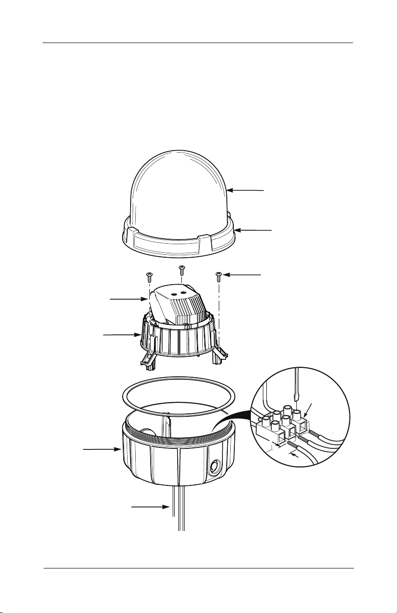
Figure 4 Connecting leads to the terminal block
PLASTIC DOME
DIECAST RING
#10 PHILLIPS
SCREW (3)
REFLECTOR
LED / MOTOR
MODULE
DIECAST
BASE
FACTORY-SUPPLIED
TERMINAL BLOCK
12
LEADS FROM
Model 371LED-120 Rotating Light
(7mm)
0.28"
TERMINAL
BLOCK

Installation and Maintenance Instructions
Safety Messages to Maintenance Personnel
Listed below are some important safety instructions and
precautions you should follow:
• Read and understand all instructions before operating this
system.
• Any maintenance to the light system must be done with the
power turned off.
• Any maintenance to the light system must be performed by a
trained electrician in accordance with NEC/CEC Guidelines
and local codes.
• Never alter the unit in any manner. Safety may be endangered
if additional openings or other alterations are made to units.
• The nameplate, which contains cautionary or other information
of importance to maintenance personnel, should not be
obscured.
• If the dome is damaged in any way, the complete dome
assembly MUST be replaced.
• After performing any maintenance, test the light system to
ensure that it is operating properly.
Failure to follow all safety precautions and instructions may result
in property damage, serious injury, or death.
Maintaining the Model 371LED-120
Establishing a regular maintenance schedule for the Model
371LED-120 extends the life of the light and ensures safety.
Periodically check that the light operates properly. Also, inspect
the dome for cracks, crazing (hairline cracks), discoloration, and
other defects.
The threaded dome ring joint should be well lubricated with
petroleum or a soap-thickened mineral oil. If corrosive products
have accumulated on joints and cannot readily be removed with
solvents, the parts should be discarded and replaced.
Model 371LED-120 Rotating Light
13

Installation and Maintenance Instructions
Cleaning the Dome
NOTE: Maintenance procedures sometimes require xtures to be
hosed down for good housekeeping. The electrical circuit should
be turned off prior to hosing down the light.
Clean the dome periodically to maintain maximum light output.
Use only mild, non-abrasive cleaning agents.
Getting Service, Assistance, and Parts
Federal Signal will service your product and provide technical
assistance and support. Please call the phone numbers listed below.
For instruction manuals and information about related products,
please go to http://www.federalsignal-indust.com.
Repair Service
Products returned for repair require a Return Authorization
form. To obtain service for the product, please contact the
Federal Signal Service Department at 708-534-4858.
Technical Assistance
For technical assistance, please call Technical Support at
708-534-3424, extension 5823.
14
Accessories and Replacement Parts
Typical replacement parts are listed on page 15. Due to
certication, certain component parts are not available for eld
replacement. Units with this type of damage must be either
replaced entirely or returned to Federal Signal for service.
The LED / Motor Modules in Table 4 on page 15 include the
following parts: motor bracket, LED PCBA, power supply
PCBA, thermal pads, standard reector, and dome gasket.
To order accessories and replacement parts, please call Federal
Signal Customer Support at 708-534-4756.
Model 371LED-120 Rotating Light
Installation and Maintenance Instructions
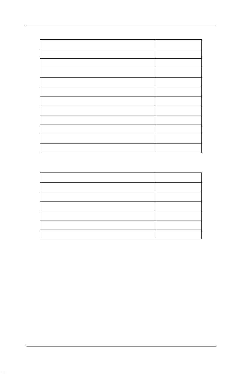
Table 4 Replacement parts
Description Part Number
Plastic Dome Assembly, Amber K8459125
Plastic Dome Assembly, Blue K8459125-01
Plastic Dome Assembly, Clear K8459125-02
Plastic Dome Assembly, Green K8459125-03
Plastic Dome Assembly, Red K8459125-04
Gasket, Surface Mount K8459127
LED / Motor Module, Amber K8459159-A
LED / Motor Module, Blue K8459159-B
LED / Motor Module, White K8459159-W
LED / Motor Module, Green K8459159-G
LED / Motor Module, Red K8459159-R
Table 5 Accessories
Description Part Number
Wall-Mount Bracket LWMB2
Corner-Mount Bracket LCMB2
Mounting Bracket, Surface 371BRCKT
Conduit Hub Kit, 3/4" NPT K8459138
Close-Up Plug, 1" NPT K8459130
22.5 Degree Reector K8459154
Model 371LED-120 Rotating Light
15
 Loading...