

Federal Signal Corporation ARJENT S2 SERIES Installation And Maintenance Instructions Manual
Page 1
2562366A
REV. A 1007
Printed in U.S.A.
INSTALLATION AND MAINTENANCE INSTRUCTIONS
FOR
ARJENT® S2 SERIES B LED/HALOGEN LIGHT ASSEMBLY
SAFETY MESSAGE TO INSTALLERS
OF
FEDERAL SIGNAL LIGHT SYSTEMS
People’s lives depend on your safe installation of our products. It is important to
read, understand and follow all instructions
shipped with the products. In addition, listed
below are some other important safety instructions and precautions you should follow:
• To properly install a light assembly: you must
have a good understanding of automotive
electrical procedures and systems, along with
proficiency in the installation and use of safety
warning equipment.
• When installing equipment or wiring inside air
bag equipped vehicles, the installer MUST en‑
sure that the equipment or wiring is installed
ONLY in areas recommended by the vehicle
manufacturer. Failure to observe this warn‑
ing will reduce the effectiveness of the air bag,
damage the air bag, or potentially damage or
dislodge the equipment, causing serious injury
or death to you or others.
• When drilling into a vehicle structure, be sure
that both sides of the surface are clear of any‑
thing that could be damaged.
• A light system is a high current device. In
order for it to function properly, a separate
ground connection must be made. If practical,
it should be connected to the negative battery
terminal. At a minimum, it may be attached
to a solid metal body or chassis part that will
provide an effective ground path as long as the
light system is to be used.
• Locate light system controls so the VEHICLE
and CONTROLS can be operated safely under
all driving conditions.
• This product contains high intensity LED de‑
vices. To prevent eye damage, DO NOT stare
into the light beam at close range.
• You should frequently inspect the light system
to ensure that it is operating properly and that
it is securely attached to the vehicle.
• File these instructions in a safe place and refer
to them when maintaining and/or reinstalling
the product.
Failure to follow all safety precautions and
instructions may result in property damage, serious
injury, or death to you or others.
I. UNPACKING.
After unpacking the Arjent S2 lightbar, inspect it for
damage that may have occurred in transit. If the unit has
been damaged, file a claim immediately with the carrier,
stating the extent of damage. Carefully check all envelopes,
shipping labels and tags before removing or destroying
them.
II. DESCRIPTION.
The Arjent S2 lightbar is available in either a 36”, 44”
or 53” length and operates on a nominal input of 13.6 volts
DC (11 volts DC minimum). Clear polycarbonate bases
along with clear or colored polycarbonate domes house a
multi‑channel programmable (via serial interface module)
circuit board assembly within the bar. The multi‑channel
PCB assembly is connected in turn to additional multiple
circuit board panels, each having the availability of 4 to 5
maximum factory‑installed options per panel. The lightbars
have an operating temperature range of ‑30°C to +65°C
(‑22°F to +149°F). They may be mounted with a hook,
permanent, or flat mounting kit to the vehicle. Available
built to order options on the Arjent S2 include:
Panelized Solaris LED Options:
XD1LC6‑A, ‑R, ‑B, ‑W, ‑G: 6‑button Solaris S2 LED
light head
XDALED‑A, ‑R, ‑B, ‑W, ‑G: 3‑button Solaris S2 LED
light head, alley light position (factory default at front
light cutoff)
• Flashing pattern selectability of the LED options
may be specified via programming of the lightbar.
See table 2.
• SignalMaster operation is accomplished via
programming of the lightbar.
4‑pos. SignalMaster available on the 36” bar;
6‑pos. SignalMaster available on the 44” bar;
8‑pos. SignalMaster available on the 53” bar
• Steady‑burn availability of 1 or 2 front LED
heads must be specified via the Arjent S2 initial
order entry.
Panelized Halogen Options (maximum of 6 per
lightbar):
XDAHAL Alley Light, 35 watts/head (MR 11)
adjustable
XDTD Takedown Light 50 watts/head
XDWL Work Light 50 watts/head
• Flashing of the halogen options is accomplished via
programming of the lightbar.
Mounting Options:
XAHKN‑SC, XAHK‑SC Hook Mount, Neutral or
Black
XAPKN‑SC, XAPK‑SC Permanent Mount, Neutral
or Black
XAFM Flat Mount
Page 2
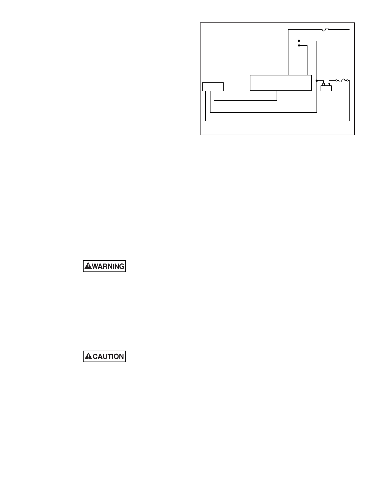
III. INSTALLATION.
290A5859
LIGHTBAR
FSC SERIAL INTERFACE MODULE
PART #8583446 REFERENCE
INSTRUCTION SHEET 2562248
SERIAL, CAT5., CONTROL CABLE
-
+
BLACK 10AWG
RED 10AWG
FUSE
40AMP
BLACK
WHITE
BLACK / WHITE
16AWG
IGNITION
1A
BATTERY
NOTICE
Improper warning system and/or two‑way radio
system operation may result if a two‑way radio
antenna is installed on, or within 18‑inches of, the
lightbar. Before permanent installation of the light‑
bar or a two‑way radio antenna, test the warning
system and two‑way radio system. DO NOT install
a two‑way radio antenna on the lightbar.
Some installations may require relocation of the
two‑way radio antenna to a trunk or fender loca‑
tion.
Warning system failure may result if additional
holes are drilled in the lightbar, or if auxiliary
devices are installed on the lightbar. DO NOT drill
additional holes in the lightbar, or install auxiliary
devices on the lightbar.
The lightbar is completely wired at the factory and
does not require any additional internal wiring; two 10
AWG power conductors (red and black) and the CAT5
communication cable exit the lightbar. All the conductors
necessary for control of any and all basic and optional
functions are contained in the CAT5 cable.
The basic light functions of the unit are communicated
via the CAT5 cable. The cable connects to either a
compatible Federal Signal Serial control head, or, a Federal
Signal Serial Interface Module.
Before proceeding, ensure that the lightbar has
been installed on the vehicle roof in accordance with the
instructions packed with the mounting kit.
Figure 1. Block Wiring Diagram.
D. SignalMaster Option.
Each lightbar is equipped for SignalMaster
operation via an external control unit or control leads on
the Interface Module (refer to paragraph III.F.). When
SignalMaster operation is not initiated, the SignalMaster
heads will flash per the selected Mode for additional light
indication to the rear.
The SignalMaster function is completely
configured at the factory and does not require any
additional wiring inside the light bar. All conductors
necessary for control of the SignalMaster is via the
compatible Serial communication control head or the
FSC #8583446 Serial Interface Module. For wiring and
operation instructions, refer to the instruction sheet
packed with the applicable control head or the FSC
Serial Interface Module’s Instruction sheet (part number
2562248).
Light system controls must be located so that
VEHICLE and CONTROLS can be operated
safely under all driving conditions.
A. See figure 1. From the lightbar, route the CAT5
control cable into the vehicle’s cab or trunk near the
eventual location of the compatible Federal Signal Serial
control head or FSC #8583446 Interface Module. An input
cable is also provided with the FSC #8583446 Serial
Interface Module.
Reverse polarity may damage any power supply
and prevent operation. Ensure that correct polarity
is observed. Unit must be fused at the source.
B. Connect the separate 10 gauge black lead to the
vehicle battery ground (‑) terminal.
C. Route and connect the 10 gauge red lead through
the supplied 40A fuse, fused at the source, to the BAT+
terminal.
E. Light Bar Controls.
The Arjent S2 functions are communicated via
the serial cable. Both the Federal Signal control head
and the Serial Interface Module are capable of providing
the following controls to the lightbar. For programming
options, refer to the Installation Manual shipped with the
Interface Module or the Federal Signal Control Head.
1. MODE 1 ‑
2. MODE 2 – overrides MODE 1;
3. MODE 3 – Overides MODES 1&2;
4. STEADY BURN RED
5. FRONT CUTOFF
6. REAR CUTOFF
7. INTERSECTION
8. FLASH HALOGEN
9. LEFT ALLEY
10. RIGHT ALLEY
11. TAKEDOWN
12. LOW POWER
13. LIGHTBAR TEST
-2-
Page 3

F. Cutoff for LED Alley Light Option.
290A5860
TAKEDOWN 50W LAMP
BI-PIN, #GH-8, #GH-9.
INSURE BULB SURFACE
IS FREE OF SEDIMENT, OILS, ETC.
REMOVE SUNSCREEN FOLD ON
PASSENGER SIDE OF BAR FOR
15A FUSE REPLACEMENTACCESS
LOCATED ON MULTI-CHANNEL
CONTROLLER PCB ASSEMBLY
FIRMLY SEAT REPLACED
BULB HORIZONTALLY
WITHIN SOCKET
B
C
D
290A5861
LED ALLEY CUTOFF JUMPER (PANEL #2005395 DRIVER & PASSENGER SIDES)
B-C PINS JUMPERED = FRONT LIGHT CUTOFF FOR DRIVER’S SIDE 2005395
PANEL (FACTORY DEFAULT)
B-C PINS JUMPERED = REAR LIGHT CUTOFF FOR PASSENGER’S SIDE
2005395 PANEL
C-D PINS JUMPERED = REAR LIGHT CUTOFF FOR DRIVER’S SIDE 2005395 PANEL
C-D PINS JUMPERED = FRONT LIGHT CUTOFF FOR PASSENGER’S SIDE 2005395
PANEL (FACTORY DEFAULT)
L22
L21
0
0
0
0
L20
L19
U7
R7
0 0 0
L26 L27 L28
U9
R31
C11
R26
C
B D
J2
L37
Q1
1
C2
R9
C1
L25
R25
L9
0
0
0
L10
L11
L12
C7
R13
The XDALED‑A, ‑R, ‑B, ‑W, ‑G option installed in
the alley position is factory set for front light cutoff of both
the passenger and driver sides of the option. The cutoff may
be changed to the rear by means of an on‑board 2‑position
jumper found on the component side fo the 2005395 panel.
The jumper is factory set across the pair of pins justified
to the front side of the lightbar. (For example: B‑C for the
driver’s side 2005395 panel denoting front cutoff of the
LED alley, and C‑D for the passenger’s side 2005395 panel
denoting front cutoff ot that LED alley.) See figure 3. The
jumper may be reset for rear cutoff by placing it across the
pins that are justified to the rear of the bar. If the jumper
is removed completely from the pins the alley light will not
function.
IV. BASIC MAINTENANCE.
Be sure to disconnect all incoming power
wiring to the lightbar before servicing the
lighbar’s interior. Failure to do so may result
in property damage, serious injury, or death
to you and others.
Disconnect ALL power to the lightbar before any
maintenance is performed.
A. Cleaning the Plastic Domes.
Ordinary cleaning of the plastic domes can be
accomplished by using mild soap and a soft rag. Should
fine scratches or a haze appear on the domes, they can
ordinarily be removed with a non‑abrasive, high quality
automotive paste wax.
Crazing (cracking) of domes will cause reduced effectiveness of light system. Do not
use cleaning agents (which will cause crazing) such as strong detergents, solvents, or
petroleum products. If crazing of domes does
occur, reliability of light for emergency warning purposes may be reduced until domes are
replaced.
B. Halogen Lamp Replacement.
A serious injury may result if lamp is touched
when hot. Always allow lamp to cool before
removing. Halogen lamps are pressurized
and if broken can result in flying glass.
Always wear gloves and eye protection when
handling the lamps.
Service life of lamp will be shortened if glass por‑
tion is touched. If glass has been handled, clean
carefully with a grease solvent.
See figures 2 and 4. Refer to table 1 and replace
the defective lamp with an exact replacement only.
Figure 2. Takedown Halogen Lamp, Fuse Replacement.
Figure 3. Cutoff for LED Alley Light Option.
-3-
Page 4

Table 1.
290A5862
35W MR11 LAMP
DISCONNECT
ATTACHED
9-CONDUCTOR
CABLE
DISCONNECT
ATTACHED
GROUND STRAP
GROUND
STRAP
290A5863
LED REFLECTOR
(REMOVE REAR SCREW)
DISCONNECT ATTACHED
GROUND STRAP FROM
END PANEL
DISCONNECT ATTACHED
9-CONDUCTOR CABLE
FROM PANEL
GROUND
STRAP
Function Description
Takedown, Worklight 50W Halogen, GH‑8 (bi‑pin)
Part No. 8107169
Alley 35W Halogen MR11
Part No. 8107241
Reflector, 6 LED 6‑Button, S2 (Solaris)
Part No. 8653104
Reflector, 3 LED Part No. 8583462
(Alley Position Option)
Multi‑channel Part No. 2005382
circuit board
panel from the lightbar. Removal of the dome above the
panel, followed by removal of the screws restraining the
panel and disconnection of the 9‑wire cable harness (see
figure 5) will allow access to the reflector’s cleaning or
replacement. Refer to table 1 for replacement part number.
NOTE
Individual LED Modules cannot be serviced. The
entire LED panel is replaced.
2. LED Panel Replacement.
C. Cleaning Reflector Assemblies.
Use a soft tissue to clean the reflectors. Avoid
heavy pressure and the use of caustic or petroleum base
solvents which will scratch or dull the surface.
D. LED Panel Replacement.
A serious injury may result if the LED assembly is touched when hot. Always allow the
LED assembly to cool before removing.
1. LED Reflector Replacement.
Individual LED reflectors may be replaced if
needed by disassembly of the LED reflector’s parent LED
In the rare occurrence a LED module is found
not functioning properly, the parent circuit board panel to
which it belongs needs to be replaced with its equivalent.
A corresponding label may be found on the topside of each
of the LED panels with a 2005xxxx‑xxxxxxxx pc board part
number and the finished model number (58300x‑xxxxx)
for ordering its replacement. See figures 4 and 5 for board
removal/replacement.
3. 15A Fuse Replacement.
Four 15A fuses are present on the main
control circuit board located on the passenger side of the
lightbar. Access the fuses by removing the sunscreen fold
from the top side of the panel to expose the control board
(see figures 2 and 7).
Figure 4. Alley MR11 Halogen Lamp Replacement.
Figure 5. LED Reflector Replacement.
-4-
Page 5

4. Control Board Replacement.
290A5864
DISCONNECT ATTACHED
9-CONDUCTOR CABLE
FROM PANEL END
MULTI-CHANNEL
CONTROLLER PCB ASSY.
FOR CONTROL BOARD REMOVAL
DISCONNECT ALL ATTACHED:
> RS485 CABLE
> POWER CABLE (RED)
> GROUND CABLE (BLACK)
> 9-CONDUCTOR PANEL HARNESSES
(PASSENGER SIDE)
DISCONNECT ATTACHED
GROUND STRAP FROM PANEL
290A55865
ARJENT S2/LEGEND LIGHTBAR CONTROLLER PCB ASSEMBLY
15A FUSES
If it is determined that the main control
board (#2005382) needs to be replaced, the inboard LED
panel on the passenger’s side must be disconnected and
removed first to gain access to the main control board.
Next, disconnect the power and ground leads to the board.
The Serial input cable must then be disconnected along
with the associated wire harness leads to the board. Last,
the four screws restraining the control board must then be
removed for its replacement (see figure 6).
Copyright 2007 Federal Signal Corporation
Figure 7. Internal vs External SignalMaster Configuration.
Figure 6. Multi-channel Controller Replacement.
-5-
Page 6

Table 2. 44” Arjent S2 Flash Pattern Lighting Standard Compliance
Table (for software revision ARJM44B and higher).
Pattern Number SAE J845 Compliant Title 13 Compliant
1 Yes Yes
2 Yes Yes
3 Yes Yes
4 Yes Yes
5 Yes Yes
6 Yes Yes
7 Yes No
8 No No
9 Yes No
10 Default Mode 1 Yes Yes
11 Yes No
12 No No
13 Yes No
14 Yes No
15 Yes No
16 No No
17 Default Mode 2 Yes No
18 No No
19 Yes No
20 Yes No
21 No No
22 Intersection No No
23 No No
24 No No
25 No No
26 Default Mode 3 Yes No
27 For testing only No No
28 For testing only No No
NOTICE
The table above identifies the light bar’s flash pattern
compliance. (for software revision ARJM44B or higher).
Patterns listed as “Yes” comply with the flash requirements
and light output requirements for the identified lighting
standard. Patterns listed as “No” do not comply with either the
flash requirements or the light output requirements for the
standard. A non‑compliant pattern should only be used after
those you are trying to warn have been trained to recognize
the pattern as a warning signal. The end user is responsible
for choosing the light patterns that meet their jurisdiction’s
requirements.
NOTE
Pattern 27 ‑ all lights on.
Pattern 28 ‑ each light sequentially lights for 2 seconds with
the exception of designated steady burn heads.
-6-
 Loading...