

Federal Signal Corporation AMR6-2570K, AMR6-100K Installation And Maintenance Instructions Manual
Page 1
Models AMR6-2570K
and AMR6-100K
High Fidelity
Two-Way Speakers
Maintenance Instructions
2562493
REV. A1 0417
Printed in U.S.A.
© Copyright 2017 Federal Signal Corporation.
Installation and
Español................p. 9
Français ...............p. 23
Page 2

Limited Warranty
This product is subject to and covered by a limited warranty, a copy of which can be found at www.fedsig.com/
SSG-Warranty. A copy of this limited warranty can also
be obtained by written request to Federal Signal Corporation, 2645 Federal Signal Drive, University Park, IL 60484,
email to info@fedsig.com or call +1 708-534-3400.
This limited warranty is in lieu of all other warranties,
express or implied, contractual or statutory, including, but
not limited to the warranty of merchantability, warranty of
tness for a particular purpose and any warranty against
failure of its essential purpose.
2645 Federal Signal Drive
University Park, Illinois 60484-3167
www.fedsig.com
Customer Support 800-344-4634 • +1 708 534-3400
Technical Support 800-524-3021 • +1 708 534-3400
Page 3

Contents
Safety Message to Installers, Users,
and Maintenance Personnel ............................................................. 1
Overview............................................................................................. 2
Unpacking the Product ..................................................................... 3
Selecting Power Tap Settings for Model AMR6-2570 ..................... 3
Selecting Power Tap Settings for Model AMR6-100K ....................4
Mounting the Speaker ....................................................................... 4
Wiring the Speaker ............................................................................ 6
Testing the Speaker ........................................................................... 6
Ordering Replacement Parts ............................................................ 8
i
Returning the Product for Credit ..................................................... 8
Obtaining Service for the Two-Way Speaker ..................................8
Obtaining Technical Assistance.......................................................8
Tables
Table 1. Power tap settings for Model AMR6-2570 ........................2
Table 2. Speaker kit contents .........................................................3
Table 3. Power tap settings for Model AMR6-2570 ........................3
Table 4. Power tap settings for Model AMR6-100K ........................4
Figures
Figure 1. Exploded view of speaker mounting................................5
Figure 2. Speakers connected in parallel .......................................7
Page 4

blank page
Page 5

Models AMR6-2570K and AMR6-100K
Safety Message to Installers, Users, and
Maintenance Personnel
It is important to follow all instructions shipped with this product.
This device is to be installed by a trained electrician who is thoroughly familiar with the National Electrical Code and will follow
NEC Guidelines as well as local codes.
The selection of the mounting location for the device, its controls
and the routing of the wiring is to be accomplished under the
direction of the facilities engineer and the safety engineer. In addition, listed below are some other important safety instructions and
precautions you should follow:
• This is not a Listed safety device and is not intended to be used
as such.
• Read and understand all instructions before installing or operating this equipment.
• Do not connect the speaker to the system while the power is
on.
1
• All effective warning speakers produce loud sounds, which may
cause in certain situations, permanent hearing loss. You should
take appropriate precautions such as wearing hearing protection.
• All effective warning speakers produce loud sounds, which may
cause, in certain situations, permanent hearing loss. The device
should be installed far enough away from potential listeners to
limit their exposure while still maintaining its effectiveness. The
OSHA Code of Federal Regulations 1910.95 Noise Standard
provides guidelines which may be used regarding permissible
noise exposure levels.
• After installation, test the sound system to ensure proper operation.
• After testing is complete, provide a copy of this instruction sheet
to all operating personnel.
• Establish a procedure to routinely check the speaker installation for integrity and proper operation. Any maintenance must
be performed by a trained electrician in accordance with NEC
Page 6
2
Models AMR6-2570K and AMR6-100K
guidelines and local codes.
Failure to follow all safety precautions and instructions may
result in property damage, serious injury, or death to you or
others.
Overview
The Federal Signal Models AMR6-2570K and AMR6-100K are
high quality, ceiling speaker kits for tone, public address, and
music reproduction in industrial, municipal and commercial ofce
environments. Power handling for these models is eight watts with
transformer taps at 8, 4, 2, 1, and 0.5 watts. Model AMR6-2570K
operates off 25 Vrms or 70 Vrms systems. Model AMR6-100K
operates off 100 Vrms systems. The kit consists of a high delity
6.5-inch two-way speaker, a powder-coated steel backbox, and a
galvanized steel tile bridge.
The AMR6-2570K and AMR6-100K include a high-delity two-way
speaker incorporating a 1-inch Mylar dome with a neodymium
tweeter.
Table 1. Power tap settings for Model AMR6-2570
Frequency Response Rating 110 Hz to 20,000 Hz
Audibility Ratings (On-Axis): 92.0 dBa at 10 feet, 8 watt tap
Weight: 2.5 lb (1.13 kg)
Dimensions:
Speaker 9.38" dia. x 2.13"
(238.3 mm dia. x 54.1 mm)
Backbox 7.5" dia. x 3.75"
(190.5 mm dia. x 191.3 mm)
Tile Bridge 23.75" x 12.75" x 0.5"
603.25 mm x 323.85 mm x 12.7
mm
Construction:
Speaker White Powder-Coated Steel
Frame and Grille
Backbox Black Powder-Coated Steel
Tile Bridge Galvanized Steel
Page 7
Models AMR6-2570K and AMR6-100K
Unpacking the Product
After unpacking the product, inspect it for damage that may have
occurred in transit. If it has been damaged, do not attempt to
install or operate it. File a claim immediately with the carrier, stating the extent of damage. Carefully check all envelopes, shipping
labels, and tags before removing or destroying them. Ensure that
the parts listed in Table 2.
Table 2. Speaker kit contents
Qty. Description
1 Speaker, 6.5", two-way, high delity
1 Steel backbox with mounting screws and speed nuts
1 Tile bridge, galvanized steel
Speaker amplier sold separately. 2 x 14 to 18 AWG wire required for
speaker connections.
Selecting Power Tap Settings for Model AMR6-2570
Model AMR6-2570, the 25/70 volt model, is factory congured for
70 Vrms, 8 watt operation. To change the setting, move the powertap wire from the 70 V, 8 W tap setting (Transformer TAP-2) to one
of the voltage and output level settings as shown in Table 3. For
example, for 70 V, 4 W operation, move the power-tap wire from
TAP-2 to TAP-3. For 25 V, 8 W operation, move the power-tap wire
to TAP-1.
3
Table 3. Power tap settings for Model AMR6-2570
Transformer Power Tap
Watt 25 V BLK (COM) 70 V BLK (COM)
0.5 TAP-5 TAP-6
1.0 TAP-4 TAP-5
2.0 TAP-3 TAP-4
4.0 TAP-2 TAP-3
8.0 TAP-1 TAP-2
Page 8

4
Models AMR6-2570K and AMR6-100K
Selecting Power Tap Settings for Model AMR6-100K
Model AMR6-100K, the 100 volt model, is factory congured for
100 volt, 8 watt operation. To change the wattage setting, move
the power-tap wire from the 8 W tap setting (Transformer TAP-5)
to one of the other output-level settings shown in Table 4.
Table 4. Power tap settings for Model AMR6-100K
Transformer Power Tap
Watt 100 V BLK (COM)
0.5 TAP-2
1.0 TAP-1
2.0 TAP-3
4.0 TAP-4
8.0 TAP-5
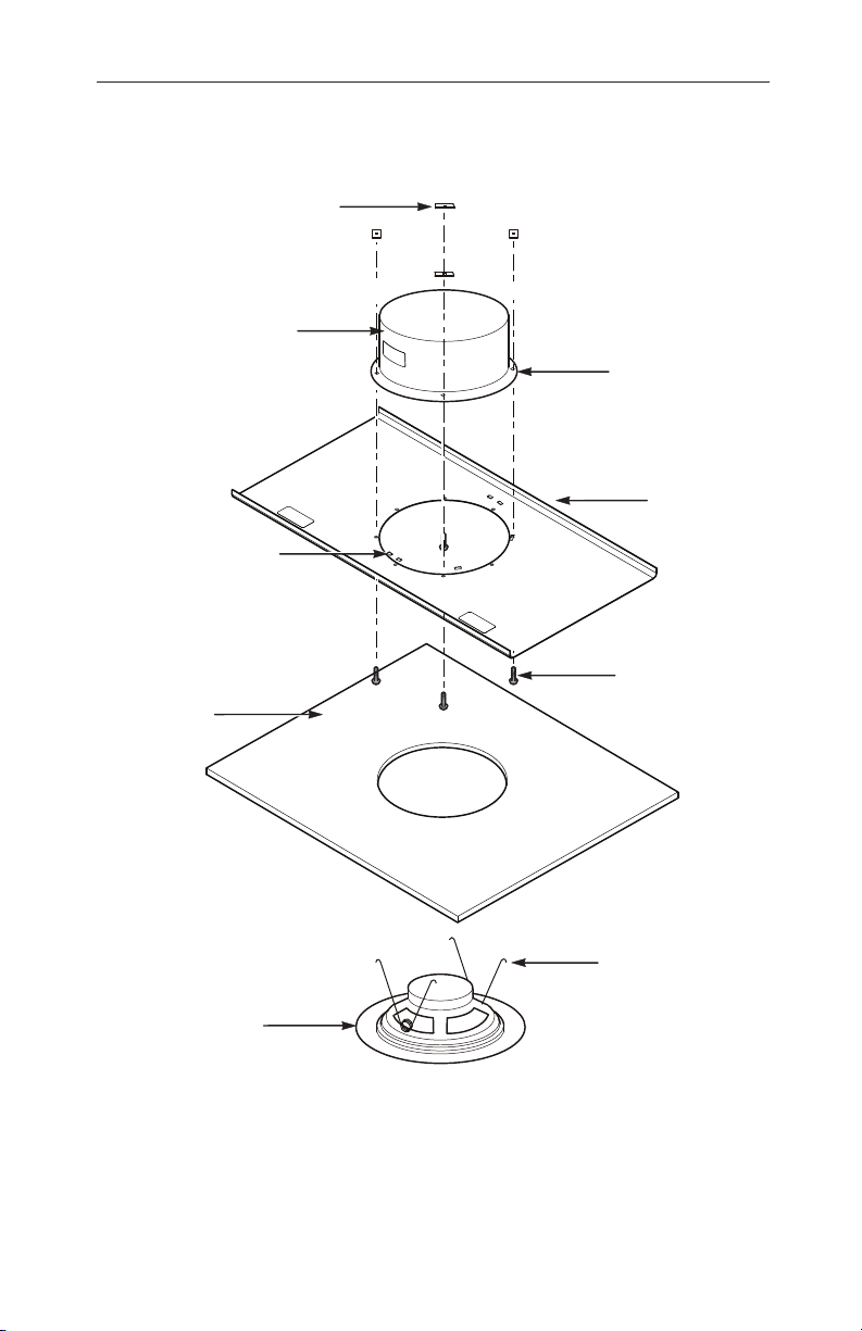
Mounting the Speaker
The mounting hardware includes a backbox and a tile bridge for
mounting the speaker in a ceiling with mounting screws and speed
nuts (Figure 1 on page 5).
1. Use a screwdriver to open knockouts in the backbox as
needed for wiring. There are four dual 3/4" x 1-1/8 in and four
5/8 in knockouts.
2. Select a mounting location and remove the ceiling tile.
3. Cut a 7.87 in (200 mm) hole in the tile for the tile bridge.
4. Slide the ange of the backbox under the six clips on the tile
bridge until all mounting holes align.
5. Secure the tile bridge to the backbox with the four #8-32 Phil-
lips screws and speed nuts included in the kit.
6 Insert the tile into the ceiling and push back an adjacent tile.
7. Insert the tile bridge/backbox assembly through the opening
you created by pushing back the adjacent tile.
8. Center the hole in the bridge/backbox assembly over the hole
you cut in the tile.
Page 9
Models AMR6-2570K and AMR6-100K
9. Before completing the installation, wire the speaker as de-
scribed on page 6.
SPEED NUTS (4)
BACKBOX
FLANGE
TILE BRIDGE
5
BACKBOX RETAINING
CLIPS (6)
CEILING TILE
SPEAKER
Figure 1. Exploded view of speaker mounting
#8-32 PHILLIPS
SCREWS (4)
TORSION
SPRINGS (2)
290A6261
Page 10

6
Models AMR6-2570K and AMR6-100K
Wiring the Speaker
SHOCK HAZARD
To avoid electrical shock, do not connect this speaker to the
system wiring when the circuits are energized.
Failure to heed this warning may result in personal injury or
death.
WIRING PRECAUTION
All wires going through holes should be protected by a grommet or convolute/split-loom tubing.
Wire the speaker in accordance with local codes.
1. Strip 1/4 inch of the insulation from 2 x 14–18 AWG wires.
2. Connect the eld wires to the corresponding speaker termi-
nals (AUDIO – and AUDIO +).
3. Connect the eld wires to a signal source that corresponds to
the voltage and output tap settings of the speakers: 25 Vrms,
70 Vrms, or 100 Vrms
4. To connect speakers in parallel, see Figure 2 on page 7.
Testing the Speaker
SOUND HAZARD
All effective warning speakers produce loud sounds, which
may cause in certain situations, permanent hearing loss. You
should take appropriate precautions such as wearing hearing
protection.
After installation, test the sound system to ensure proper operation.
Page 11

Models AMR6-2570K and AMR6-100K
AUDIO (+)
290A6289
(−)(+)
7
VOLTAGE AND OUTPUT TAPS
TAPS
5 6 7 8
4 3 2 1
AudioMaster
MODEL: AMR6-2570K SERIES A
VOLTS: 100 Vrms FREQ. 110-20000 Hz
14 AWG–18 AWG
25 Vrms, 70 Vrms, OR 100 Vrms
SIGNAL SOURCE
(−)(+)
TAPS
5 6 7 8
4 3 2 1
AudioMaster
MODEL: AMR6-2570K SERIES A
VOLTS: 100 Vrms FREQ. 110-20000 Hz
AUDIO (−)
Figure 2. Speakers connected in parallel
Page 12

8
Models AMR6-2570K and AMR6-100K
Ordering Replacement Parts
To order replacement parts, please call Federal Signal Customer
Support at 708-534-4756.
Returning the Product for Credit
Product returns for credit require a return authorization from your
local distributor prior to returning the product to Federal Signal.
Please contact your distributor for assistance.
A product is qualied to be returned for credit when the following
conditions are met:
• Product is resalable and in the original cartons
• Product has not been previously installed
• Product is the current revision
• Product has not been previously repaired
• Product is a standard product
• Product is not a service part
All returns are subject to a re-stock fee.
Defective products that are returned within the warranty period will
be repaired or replaced at Federal Signal’s sole discretion. Defective products do not include those products with lamp failure.
Circumstances other than those listed above will be addressed on
a case-by-case basis.
Obtaining Service for the Two-Way Speaker
Products returned for repair require a Return Authorization form.
To obtain service for the Models AMR6-2570K and AMR6-100K,
please contact the Federal Signal Service Department at
708-534-4858.
Obtaining Technical Assistance
For technical assistance, please call Federal Signal Technical
Support at 708-534-3400.
Page 13

Altavoces de dos vías
de alta delidad, modelos
AMR6-2570K y AMR6-100K
9
Instrucciones de
instalación y mantenimiento
Page 14

10
Garantía limitada
Este producto está sujeto a y cubierto por una garantía
limitada, cuya copia se puede encontrar en www.fedsig.
com/SSG-Warranty. Una copia de esta garantía limitada
también se puede obtener mediante solicitud por escrito
a Federal Signal Corporation, 2645 Federal Signal Drive,
University Park, IL 60484, a través del envío de un correo
electrónico a info@fedsig.com o si llama al +1 708-534-
3400.
Esta garantía limitada reemplaza a todas las demás
garantías, expresas o implícitas, contractuales o legales,
incluida, entre otras, la garantía de comerciabilidad, la
garantía de idoneidad para un propósito en articular y
cualquier garantía contra la imposibilidad de cumplir con
su nalidad fundamental.
Sistemas de seguridad y protección
2645 Federal Signal Drive
University Park, Illinois 60484
www.fedsig.com
Atención al cliente 800-344-4634 • +1 708 534-3400
Soporte técnico 800-524-3021 • +1 708 534-3400
Page 15

Contenido
Aviso sobre seguridad para instaladores, usuarios y
personal de mantenimiento ............................................................ 13
Descripción general ........................................................................ 14
Desempaque del producto .............................................................15
Selección de las posiciones de toma de potencia
para el modelo AMR6-2570 ............................................................. 16
Selección de las posiciones de toma de potencia
para el modelo AMR6-100K ............................................................16
Montaje del altavoz..........................................................................17
Cableado del altavoz ....................................................................... 19
Prueba del altavoz ........................................................................... 19
Pedido de partes de repuesto ........................................................ 21
11
Devolución del producto a cambio de crédito ..............................21
Obtención de servicio para el altavoz de dos vías.......................21
Obtención de asistencia técnica .................................................... 21
Tablas
Tabla 1. Especicaciones del producto ........................................14
Tabla 2. Contenido del juego de altavoz.......................................15
Tabla 3. Posiciones de toma de potencia
para el modelo AMR6-2570 ..........................................................16
Tabla 4. Posiciones de toma de potencia
para el modelo AMR6-100K .........................................................17
Page 16

12
Figuras
Figura 1. Vista detallada del montaje del altavoz .........................18
Figura 2. Altavoces conectados en paralelo .................................20
blank page
Page 17

Modelos AMR6-2570K y AMR6-100K
Aviso sobre seguridad para instaladores, usuarios y personal de mantenimiento
Es importante seguir todas las instrucciones incluidas con este
producto. Este dispositivo debe ser instalado por un electricista
capacitado y completamente familiarizado con el Código Eléctrico
Nacional (NEC, por sus siglas en inglés) que sepa observar las
pautas del NEC al igual que los códigos locales.
La selección de la ubicación de montaje para el dispositivo, sus
controles y el enrutamiento del cableado deberá llevarse a cabo
de acuerdo con las instrucciones del ingeniero de las instalaciones y el ingeniero de seguridad. Asimismo, a continuación señalamos algunas precauciones y normas de seguridad importantes
que deberá seguir al realizar la instalación:
• Éste no es un dispositivo de seguridad clasicado y no está
diseñado para usarlo con ese propósito.
• Lea y entienda todas las instrucciones antes de proceder con la
instalación o la operación de este equipo.
13
• No conecte el altavoz al sistema mientras la potencia esté conectada.
• Todos los altavoces de advertencia en buen funcionamiento
producen sonidos fuertes que podrían ocasionar, en ciertas
situaciones, pérdida permanente de la audición. Deberá tomar
las precauciones debidas tales como utilizar protección para los
oídos.
• Todos los altavoces de advertencia en buen funcionamiento
producen sonidos fuertes que podrían ocasionar, en ciertas situaciones, pérdida permanente de la audición. El dispositivo se
debe instalar lo sucientemente lejos de los posibles oyentes
para limitar su exposición al ruido mientras se mantiene aún su
ecacia. El Código de Regulaciones Federales de OSHA en su
Norma sobre Ruidos 1910.95 proporciona pautas que pueden
utilizarse con respecto a los niveles admisibles de exposición al
ruido.
Page 18

14
Modelos AMR6-2570K y AMR6-100K
• Después de la instalación, pruebe el sistema de sonido para asegu-
rarse que esté funcionando correctamente.
• Luego de nalizada la prueba, proporcióneles una copia de
esta hoja de instrucciones a todo el personal de operación.
• Establezca un procedimiento de revisión rutinaria de la insta-
lación del altavoz para vericar su integridad y funcionamiento
correcto. Todo mantenimiento deberá ser realizado por un
electricista capacitado de acuerdo con las pautas del NEC y los
códigos locales.
De no tomar estas precauciones ni seguir estas instrucciones pueden ocasionarse daños materiales, lesiones graves o
ponerse en peligro su vida y la de los demás.
Descripción general
Los modelos AMR6-2570K y AMR6-100K de Federal Signal son
juegos de altavoces de cielo raso de alta calidad para la reproducción de música, tonos y para hablar al público en entornos
de ocinas comerciales, municipales e industriales. El manejo
de potencia para estos modelos es de ocho vatios con tomas de
transformador a 8, 4, 2, 1, y 0.5 vatios. El modelo AMR6-2570K
funciona con sistemas de 25 Vrms o 70 Vrms. El modelo AMR6100K funciona con sistemas de 100 Vrms. El juego consta de un
altavoz de dos vías de 6.5 pulg. de alta delidad, una caja posterior de acero con revestimiento pulverizado, y un puente de panel
de acero galvanizado.
Los modelos AMR6-2570K y AMR6-100K incluyen un altavoz de
dos vías de alta delidad con domo de Mylar de 1 pulg. incorporado, equipado con un altavoz de agudos de neodimio.
Tabla 1. Especicaciones del producto
Capacidad de respues-
110 Hz a 20,000 Hz
ta de frecuencia:
Capacidades de
92.0 dBa a 10 pies, toma de 8 vatios
audibilidad (en eje):
Peso: 2.5 lb (1.13 kg)
Page 19

Modelos AMR6-2570K y AMR6-100K
Dimensiones:
Altavoz 9.38 pulg. de diá. x 2.13 pulg.
(238.3 mm de diá. x 54.1 mm)
Caja posterior 7.5 pulg. de diá. x 3.75 pulg.
(190.5 mm de diá. x 95.3 mm)
Puente de panel 23.75 pulg. x 12.75 pulg. x 0.5 pulg.
(603.25 mm x 323.85 mm x 12.7 mm)
Construcción:
Altavoz Rejilla y caja de acero con
revestimiento pulverizado blanco
Caja posterior Acero con revestimiento
pulverizado negro
Puente de panel Acero galvanizado
Desempaque del producto
Después de desempacar el producto, inspeccione si han ocurrido
daños durante el envío. Si el producto ha sufrido daños, no intente
instalarlo o ponerlo en funcionamiento. Entable una reclamación
inmediatamente con el transportista, e indique la extensión de los
daños. Verique cuidadosamente todos los sobres, etiquetas de
envío y marbetes antes de removerlos o destruirlos. Verique que
haya recibido las partes enumeradas en la Tabla 2.
15
Tabla 2. Contenido del juego de altavoz
Cant. Descripción
1 Altavoz, 6.5 pulg., dos vias, alta fidelidad,
1 Caja posterior de acero con tornillos y tuercas rápidas
de montaje
1 Puente de panel, de acero galvanizado
El amplicador del altavoz se vende por separado. Para las conexiones a
los altavoces se necesita un cableado de 2 x 14 a 18 AWG.
Page 20

16
Modelos AMR6-2570K y AMR6-100K
Selección de las posiciones de toma de potencia para el modelo AMR6-2570
El modelo AMR6-2570, de 25/70 voltios, viene congurado de fábrica para funcionar con 70 Vrms, 8 vatios. Para cambiar el ajuste,
mueva el conductor de toma de potencia desde la posición de
derivación para 70 V, 8 vatios (TOMA 2 [TAP-2] en el transformador) a una de las posiciones de nivel de salida y voltaje como se
muestra en Tabla 3. Por ejemplo, para funcionamiento con 70 V,
4 vatios, mueva el conductor de toma de potencia desde la
posición TOMA 2 (TAP-2) a la posición TOMA 3 (TAP-3). Para el
funcionamiento con 25 V, 8 vatios, mueva el conductor de toma de
potencia a la posición TOMA 1 (TAP-2 a TAP-1).
Tabla 3. Posiciones de toma de potencia
para el modelo AMR6-2570
Toma de potencia del transformador
Vatios 25 V NEGRO (COM) 70 V NEGRO (COM)
0.5 TOMA-5 TOMA-6
1.0 TOMA-4 TOMA-5
2.0 TOMA-3 TOMA-4
4.0 TOMA-2 TOMA-3
8.0 TOMA-1 TOMA-2
Selección de las posiciones de toma de potencia para el modelo AMR6-100K
El modelo AMR6-100K, de 100 voltios, viene congurado de fábrica para funcionar con 100 voltios, 8 vatios. Para cambiar el ajuste
de vataje, mueva el conductor de toma de potencia de la posición
de derivación para 8 vatios (TOMA 5 [TAP-5] en el transformador)
a una de las otras posiciones de nivel de salida mostradas en la
Tabla 4 en la página 17.
Page 21

Modelos AMR6-2570K y AMR6-100K
Tabla 4. Posiciones de toma de potencia
para el modelo AMR6-100K
Toma de potencia del transformador
Vatios 100 V NEGRO (COM)
0.5 TOMA-2
1.0 TOMA-1
2.0 TOMA-3
4.0 TOMA-4
8.0 TOMA-5
Montaje del altavoz
Con los herrajes de montaje se incluyen una caja posterior y un
puente de panel para montar el altavoz en un cielo raso con torni-
llos y tuercas de montaje (véase al gura 1 en la página 18).
1. Utilice un destornillador para destapar agujeros ciegos en la
caja posterior según sea necesario para el cableado. Hay
cuatro agujeros ciegos de 5/8 pulg. y cuatro dobles de 3/4
pulg. x 1-1/8 pulg.
17
2. Seleccione un lugar de montaje y retire el panel de cielo raso.
3. Corte un agujero de 7.87 pulg. (200 mm) en el panel para el
puente de panel.
4. Deslice la pestaña de la caja posterior debajo de las seis
presillas en puente de panel hasta que todos los agujeros de
montaje estén alineados.
5. Fije el puente de panel en la caja posterior con los cuatro tor-
nillos Phillips No. 8-32 y tuercas rápidas incluidas en el juego.
6 Inserte el panel en el cielo raso y empuje un panel adyacente
hacia atrás.
7. Inserte el conjunto del puente de panel y caja posterior a
través de la abertura creada anteriormente cuando usted
empujó el panel adyacente hacia atrás.
8. Centre el agujero en el conjunto del puente y caja posterior
sobre el agujero que usted cortó en el panel.
Page 22

18
Modelos AMR6-2570K y AMR6-100K
9. Antes de nalizar la instalación, cablee el altavoz como se
describe en la página 19.
TUERCAS RAPIDAS (4)
CAJA POSTERIOR
PUENTE DE PANEL
PRESILLAS DE RETENCION
DE LA CAJA POSTERIOR (6)
TORNILLOS
PHILLIPS No. 8-32 (4)
PANEL DE CIELO RASO
PESTAÑA
RESORTES DE
TORSION (2)
ALTAV OZ
Figura 1. Vista detallada del montaje del altavoz
290A6294
Page 23

Modelos AMR6-2570K y AMR6-100K
Cableado del altavoz
RIESGO DE DESCARGA ELECTRICA
Para evitar un choque eléctrico, no conecte este altavoz en el
cableado del sistema cuando los circuitos estén energizados.
El incumplimiento de esta advertencia pueden ocasionarse
lesiones personales o la muerte.
PRECAUCION PARA EL CABLEADO
Todos los conductores o cables que pasen a través de agujeros se deben proteger con tubos convultos o tubos con
cableado interno partidos.
Conecte el altavoz de acuerdo con los códigos locales.
1. Desforre 1/4 pulg. de aislamiento del cableado 2 x 14–18
AWG.
2. Conecte los conductores de campo en las terminales corres-
pondientes del altavoz (AUDIO – y AUDIO +).
19
3. Conecte los conductores de campo a una fuente de señal
que corresponda con el voltaje y la posición de derivación de
salida de los altavoces: 25 Vrms, 70 Vrms, o 100 Vrms
4. Para conectar los altavoces en paralelo, consulte la gura 2
en la página 20.
Prueba del altavoz
RIESGO DEL SONIDO
Todos los altavoces de advertencia en buen funcionamiento producen sonidos fuertes que podrían ocasionar, en ciertas situaciones, pérdida permanente de la audición. Deberá tomar las precauciones debidas tales como utilizar protección para los oídos.
Después de la instalación, pruebe el sistema de sonido para asegurarse
que esté funcionando correctamente.
Page 24

AUDIO (+)
290A6295
20
Modelos AMR6-2570K y AMR6-100K
(−)(+)
TOMAS DE VOLTAJE Y SALIDA
TAPS
5 6 7 8
4 3 2 1
AudioMaster
MODEL: AMR6-2570K SERIES A
VOLTS: 100 Vrms FREQ. 110-20000 Hz
14 AWG–18 AWG
25 Vrms, 70 Vrms, O 100 Vrms
FUENTE DE SEÑAL
(−)(+)
TAPS
5 6 7 8
4 3 2 1
AudioMaster
MODEL: AMR6-2570K SERIES A
VOLTS: 100 Vrms FREQ. 110-20000 Hz
AUDIO (−)
Figura 2. Altavoces conectados en paralelo
Page 25

Modelos AMR6-2570K y AMR6-100K
Pedido de partes de repuesto
Para pedir partes de repuesto, por favor llame al Servicio de Asistencia al Cliente de Federal Signal, al número 708-534-4756.
Devolución del producto a cambio de crédito
Las devoluciones del producto a cambio de crédito por el mismo
requieren una autorización de devolución de su distribuidor local
antes de devolver el producto a Federal Signal. Póngase en contacto con su distribuidor para obtener ayuda.
Un producto calica para ser devuelto a cambio de crédito cuando
éste cumple las siguientes condiciones:
• El producto se puede volver a vender y está en sus cajas
originales
• El producto no se ha instalado previamente
• El producto es de la revisión actual
• El producto no ha sido reparado previamente
• El producto es un producto estándar
• El producto no es una parte de repuesto
Todas las devoluciones están sujetas a un cargo de realmacenamiento.
21
Los productos defectuosos que se devuelvan dentro del período
de la garantía serán reparados o reemplazados a discreción única
de Federal Signal. Los productos defectuosos no incluyen aquellos productos con avería de lámpara.
Las circunstancias, otras que aquellas indicadas anteriormente,
serán atendidas en base a caso por caso.
Obtención de servicio para el altavoz de dos vías
Los productos que se devuelvan para ser reparados requieren un
formulario de Autorización de Devolución. Para obtener servicio
para los modelos AMR6-2570K y AMR6-100K, por favor llame al Departamento de Servicio de Federal Signal, al número 708-534-4858.
Obtención de asistencia técnica
Para solicitar asistencia técnica, por favor llame al Servicio de
Soporte Técnico de Federal Signal, al número 708-534-3400.
Page 26

blank page
Page 27

Haut-parleurs bidirectionnels
haute délité –
Modèles AMR6-2570K et
AMR6-100K
23
Instructions d’installation
et d’entretien
Page 28

24
Garantie limitée
Le présent produit est sujet à une garantie limitée et est
couvert par celle-ci. Vous pouvez obtenir une copie de
cette dernière sur le site www.fedsig.com/SSG-Warranty.
Vous pouvez également obtenir une copie de la présente
garantie limitée en envoyant une demande écrite à
Federal Signal Corporation, 2645 Federal Signal Drive,
University Park, IL 60484, en envoyant un e-mail à info@
fedsig.com ou en appelant le +1 708-534-3400.
La présente garantie limitée remplace toutes les autres
garanties, explicites ou implicites, contractuelles ou
légales, y compris, mais sans se limiter à la garantie de
qualité marchande, la garantie d’habitabilité à une n
particulière et toute garantie contre une défaillance de sa
nalité essentielle.
Systèmes de sûreté et de sécurité
2645 Federal Signal Drive
University Park, Illinois 60484
www.fedsig.com
Service client : 800-344-4634 • +1 708 534-3400
Support technique : 800-524-3021 • +1 708 534-3400
Page 29

Table des matières
Message de sécurité destiné aux installateurs
et au personnel d’entretien.............................................................27
Aperçu .............................................................................................. 28
Déballage du produit ....................................................................... 29
Sélection de la conguration de la prise de réglage
pour le modèle AMR6-2570 ............................................................. 29
Sélection de la conguration de la prise de réglage
pour le modèle AMR6-100K ............................................................30
Montage du haut-parleur ................................................................31
Câblage du haut-parleur ................................................................. 33
Vérication du système de son......................................................33
Commande de pièces de rechange ...............................................35
25
Renvoyer le produit et obtenir un crédit ....................................... 35
Réparation de votre haut-parleur bidirectionnel .......................... 35
Obtention d’une aide technique ..................................................... 35
Tableaux
Tableau 1. Spécications du produit ............................................. 28
Tableau 2. Contenu du kit de haut-parleur ...................................29
Tableau 3. Congurations de la prise de
réglage pour le modèle AMR6-2570 .............................................30
Tableau 4. Congurations de la prise de réglage
pour le modèle AMR6-100K .........................................................30
Page 30

26
Figures
Figure 1. Vue éclatée du montage du haut-parleur ......................32
Figure 2. Haut-parleurs connectés en parallèle............................34
blank page
Page 31

Modèles AMR6-2570K et AMR6-100K
Message de sécurité destiné aux installateurs et
au personnel d’entretien
Veuillez suivre toutes les instructions fournies avec ce produit. Cet
appareil doit être installé par un électricien qualié qui connaît parfaitement le Code national de l’électricité et suivra les directives
du CNE et les codes locaux.
La détermination d’un emplacement pour le montage de l’appareil,
sa commande et l’acheminement du câblage doit être exécutée
sous la direction de l’ingénieur d’entretien et de l’ingénieur de la
sécurité des installations. De plus, d’autres instructions importantes relatives à la sécurité et d’autres précautions à suivre
gurent dans la liste ci-dessous :
• Ceci n’est pas un dispositif de sécurité homologué et il n’est
pas prévu pour une telle utilisation.
• Veuillez lire et comprendre toutes les instructions avant d’installer ou d’utiliser cet équipement.
• Ne connectez pas ce dispositif au système lorsque ce dernier
est sous tension.
27
• Tous les haut-parleurs d’avertissement efcaces émettent des
sons élevés qui peuvent entraîner dans certains cas un décit
auditif permanent. Vous devez prendre les précautions néces-
saires, comme le port d’un dispositif de protection anti-bruit.
• Tous les haut-parleurs d’avertissement efcaces émettent des
sons élevés qui peuvent entraîner dans certains cas un décit
auditif permanent. Le dispositif doit être installé sufsamment
loin des auditeurs potentiels pour limiter leur exposition, tout en
gardant son efcacité. Le Code of Federal Regulations 1910.95
Noise Standard de l’OSHA fournit des directives utiles sur les
niveaux permissibles d’exposition au bruit.
• Après l’installation, vériez le système de son pour vous assurez de
son bon fonctionnement.
• Lorsque la vérication est terminée, fournissez une copie du
manuel d’instructions à tout le personnel utilisateur.
Page 32

28
Modèles AMR6-2570K et AMR6-100K
• Établissez une procédure de vérication régulière de l’instal-
lation et du fonctionnement de ce haut-parleur. Tout entretien
doit être effectué par un électricien qualié, conformément aux
directives du CNE et des codes locaux.
Le non-respect de ces consignes peut entraîner des dommages matériels ou des blessures graves, voire mortelles
pour vous ou pour les autres.
Aperçu
Les modèles AMR6-2570K et AMR6-100K de Federal Signal sont
des kits de haut-parleur de plafond de qualité supérieure, permettant de diffuser des tonalités, des annonces publiques et de la
musique dans des environnements industriels, municipaux et des
bureaux commerciaux. La puissance admissible de ces modèles
est de huit watts ; ils sont dotés de prises de transformateur de
8, 4, 2, 1 et 0,5 watts. Le modèle AMR6-2570K fonctionne sur
des systèmes de 25 Vrms ou 70 Vrms. Le modèle AMR6-100K
fonctionne sur des systèmes de 100 Vrms. Ce kit est composé
d’un haut-parleur bidirectionnel haute délité de 6,5 pouces, d’un
caisson en acier, revêtement poudre et d’un pont d’appui en acier
galvanisé.
Les modèles AMR6-2570K et AMR6-100K sont des haut-parleurs
bidirectionnels haute délité dotés d’un dôme Mylar d’1 pouce et
d’un haut-parleur d’aigu avec aimant néodyme.
Tableau 1. Spécications du produit
Réponse en fréquence 110 Hz à 20 000 Hz
Fréquence audible (dans
l’axe) :
92 dBa à 10 pi (3 m), prise de
réglage de 8 watts
Poids : 2,5 lb (1,13 kg)
Dimensions :
Haut-parleur 9,38 po diam. x 2,13 po
(238,3 mm diam. x 54,1 mm)
Caisson 7,5 po dia. x 3,75 po
(190,5 mm diam. x 191,3 mm)
Pont d’appui 23,75 po x 12,75 po x 0,5 po
603,25 mm x 323,85 mm x 12,7 mm
Page 33

Modèles AMR6-2570K et AMR6-100K
Construction :
Haut-parleur Boîtier et grille en acier en acier
blanc, revêtement poudre
Caisson Acier noir, revêtement poudre
Pont d’appui Acier galvanisé
Déballage du produit
Après avoir déballé le produit, inspectez-le pour vérier qu’aucun
dommage n’est survenu lors du transport. Si l’appareil a été
endommagé, n’essayez pas de l’installer ou de l’utiliser. Dépo-
sez immédiatement une réclamation auprès du transporteur en
précisant l’étendue des dommages. Vériez avec soin toutes les
enveloppes, étiquettes d’expédition et autres étiquettes avant de
les enlever ou de les détruire. Vériez que les pièces énumérées
au Tableau 2 sont bien présentes.
Tableau 2. Contenu du kit de haut-parleur
Qté. Description
1 Haut-parleur, 6,5 po, bidirectionnel, haute délité
1 Caisson en acier doté de vis de montage et d’écrous à
ressorts
1 Pont d’appui en acier galvanisé
Amplicateur de haut-parleur vendu séparément. 2 ls de calibre 14 à 18
AWG requis pour le branchement du haut-parleur.
29
Sélection de la conguration de la prise de réglage
pour le modèle AMR6-2570
Le modèle AMR6-2570, de 25/70 volt est conguré en usine pour
fonctionner à 70 Vrms, 8 watts. Pour modier la conguration,
enlevez le l connecté à la prise de réglage de 70 V, 8 W (Transformateur TAP-2) et connectez-le à l’un des réglages de tension
et de niveau de sortie illustrés au Tableau 3 à la page 30. Par
exemple, pour un fonctionnement sur 70 V, 4 W, enlevez le l
connecté à la prise de réglage TAP-2 et connectez-le à TAP-3.
Pour un fonctionnement sur 25 V, 8 W, connectez-le à TAP-1.
Page 34

30
Modèles AMR6-2570K et AMR6-100K
Tableau 3. Congurations de la prise de
réglage pour le modèle AMR6-2570
Prise de réglage transformateur
Watts 25 V NOIR (COM) 70 V NOIR (COM)
0.5 TAP-5 TAP-6
1.0 TAP-4 TAP-5
2.0 TAP-3 TAP-4
4.0 TAP-2 TAP-3
8.0 TAP-1 TAP-2
Sélection de la conguration de la prise de
réglage pour le modèle AMR6-100K
Le modèle AMR6-100K, de 100 volt est conguré en usine pour
fonctionner sur 100 volt, 8 watts. Pour modier la conguration de
la puissance, enlevez le l connecté à la prise de réglage de 8 W
(Transformateur TAP-5) et connectez-le sur l’un des réglages de
tension et de niveau de sortie illustrés au Tableau 4.
Tableau 4. Congurations de la prise de
réglage pour le modèle AMR6-100K
Prise de réglage transformateur
Watts 100 V NOIR (COM)
0.5 TAP-2
1.0 TAP-1
2.0 TAP-3
4.0 TAP-4
8.0 TAP-5
Page 35

Modèles AMR6-2570K et AMR6-100K
Montage du haut-parleur
Le matériel de montage inclut un caisson et un pont d’appui destinés à monter le haut-parleur sur un plafond à l’aide des vis et des
boulons de montage (voir la gure 1 à la page 32).
1. Enfoncez les alvéoles défonçables du caisson au moyen
d’un tournevis an d’acheminer les ls. Il y a quatre alvéoles
défonçables jumelées de 3/4 po x 1-1/8 po et quatre alvéoles
défonçables de 5/8 po.
2. Sélectionnez un emplacement de montage et retirez la plaque
de plafond.
3. Découpez un trou de 7,87 po (200 mm) dans la plaque an
de faire passer le pont d’appui.
4. Faites glisser la bride du caisson sous les six attaches du
pont d’appui jusqu’à ce que les trous de montage soient alignés.
5. Fixez le pont d’appui au caisson à l’aide des quatre vis Phil-
lips nº 8-32 et des écrous à ressort inclus dans le kit.
31
6 Insérez la plaque dans le plafond et repoussez la plaque
adjacente.
7. Insérez l’assemblage du pont d’appui/caisson dans l’ouver-
ture que vous avez créée en repoussant la plaque adjacente.
8. Centrez le trou de l’assemblage du pont/caisson sur le trou
que vous avez découpé dans la plaque.
9. Avant de nir l’installation, câblez le haut-parleur de la façon
décrite à la page 33.
Page 36

32
Modèles AMR6-2570K et AMR6-100K
ÉCROUS À RESSORTS (4)
CAISSON
BRIDE
PONT D’APPUI
ATTACHES DU CAISSON (6)
VIS PHILLIPS n° 8-32 (4)
PLAQUE DE PLAFOND
RESSORT DE TORSION (2)
HAUT-PARLEUR
Figure 1. Vue éclatée du montage du haut-parleur
290A6296
Page 37

Modèles AMR6-2570K et AMR6-100K
Câblage du haut-parleur
RISQUE DE DÉCHARGE ÉLECTRIQUE
Pour éviter toute décharge électrique, ne connectez pas ce
haut-parleur au câblage du système lorsque les circuits sont
sous tension.
Le non respect de cet avertissement peut entraîner des blessures graves, voire mortelles.
PRÉCAUTIONS À PRENDRE LORS DU CÂBLAGE
Tous les ls passant par des trous doivent être protégés par
un œillet ou un tube fendu/convoluté.
Câblez le haut-parleur conformément aux codes locaux. Consultez la gure 2 de la page 34.
1. Dénudez 1/4 po d’isolant à l’extrémité des 2 ls de calibre
14–18 AWG.
2. Connectez les ls in-situ aux bornes de haut-parleur corres-
pondantes (AUDIO – et AUDIO +).
33
3. Connectez les ls in-situ à une source sonore correspondant
à la conguration de la prise de réglage de la puissance de
sortie et de tension des haut-parleurs 25 Vrms, 70 Vrms, ou
100 Vrms.
4. Pour connecter les haut-parleurs en parallèle, consultez la
gure 2 de la page 34.
Vérication du système de son
RISQUE DE SON
Tous les haut-parleurs d’avertissement efcaces émettent
des sons élevés qui peuvent entraîner dans certains cas un
décit auditif permanent. Vous devez prendre les précautions
nécessaires, comme le port d’un dispositif de protection anti-
bruit.
Après l’installation, vériez le système de son pour vous assurez de son
bon fonctionnement.
Page 38

AUDIO (+)
290A6297
34
Modèles AMR6-2570K et AMR6-100K
(−)(+)
PRISE DE RÉGLAGE DE SORTIE
ET DE TENSION
TAPS
5 6 7 8
4 3 2 1
AudioMaster
MODEL: AMR6-2570K SERIES A
VOLTS: 100 Vrms FREQ. 110-20000 Hz
14 AWG–18 AWG
25 Vrms, 70 Vrms, OU 100 Vrms
SOURCE SONORE
(−)(+)
TAPS
5 6 7 8
4 3 2 1
AudioMaster
MODEL: AMR6-2570K SERIES A
VOLTS: 100 Vrms FREQ. 110-20000 Hz
AUDIO (−)
Figure 2. Haut-parleurs connectés en parallèle
Page 39

Modèles AMR6-2570K et AMR6-100K
Commande de pièces de rechange
Pour commander des pièces de rechange, appelez le service à la
clientèle de Federal Signal au 708-534-4756.
Renvoyer le produit et obtenir un crédit
Avant de renvoyer tout produit en vue d’obtenir un crédit, vous devez obtenir une autorisation de renvoi auprès de votre distributeur
local. Veuillez contacter votre distributeur an d’obtenir de l’aide.
Un produit peut être renvoyé an d’obtenir un crédit si les condi-
tions suivantes sont respectées :
• Le produit peut être revendu et est renvoyé dans son
emballage d’origine
• Le produit n’a pas encore été installé
• Le produit est le modèle le plus récent
• Le produit n’a jamais été réparé
• Le produit est un produit normalisé
• Le produit n’est pas une pièce détachée
35
Tous les renvois de produits font l’objet de frais de restockage.
Les produits défectueux renvoyés au cours de la période de garantie seront réparés ou remplacés selon le bon vouloir de Federal
Signal. Les produits dont la lampe est défectueuse ne sont pas
considérés comme des produits défectueux.
Toute demande autre que celles citées ci-dessus sera examinée
au cas par cas.
Réparation de votre haut-parleur bidirectionnel
Les produits renvoyés pour être réparés doivent être accompa-
gnés d’un formulaire d’autorisation de renvoi. Pour faire réparer
vos modèles AMR6-2570K and AMR6-100K, veuillez contacter le
service après-vente de Federal Signal au 708-534-4858.
Obtention d’une aide technique
Pour obtenir une aide technique, appelez le service après-vente
de Federal Signal au 708-534-3400.
Page 40

2645 Federal Signal Drive
University Park, Illinois 60484-3167
www.fedsig.com
Customer Support 800-344-4634 • +1 708 534-3400
Technical Support 800-524-3021 • +1 708 534-3400
 Loading...