


MODELS FB2PST AND FB2PST-I
INSTRUCTION SHEET FOR FEDERAL MODELS FB2PST (12-24VDC, 120VAC
AND 230-240VAC), FB2PST-I (24VDC) FIREBALL® LIGHTS
MODELOS FB2PST Y FB2PST-I
HOJA DE INSTRUCCIONES PARA LOS MODELOS FEDERAL FB2PST
(12-24VCC, 120VCA Y 230-240VCA), FB2PST-I (24VCC)
DE LUCES FIREBALL®
MODÈLES FB2PST ET FB2PST-I
FEUILLET D’INSTRUCTIONS POUR LES LAMPES FIREBALL® FEDERAL
MODÈLES FB2PST (12-24 V.C.C., 120 V.C.A., ET 230-240 V.C.A.),
FB2PST-I (24 V.C.C.)
Address all communications and shipments to:
Dirija toda la correspondencia y envíos a:
Adressez toutes les communications et expéditions à:
FEDERAL SIGNAL CORPORATION
Electrical Products Division
2645 Federal Signal Drive
University Park, IL 60466-3195


INSTRUCTION SHEET FOR FEDERAL MODELS FB2PST AND FB2PST-I (12-24VDC,
24VDC, 120VAC AND 230-240VAC)
I. INSTALLATION.
SAFETY MESSAGE TO INSTALLERS
NOTE
Installation, maintenance and disposal of this product must be carried out in accordance with
national codes and standards.
It is important to follow all instructions shipped with this product. This device is to be installed by a
trained electrician who is thoroughly familiar with and will follow all applicable national and local
codes in the country of use.
This device should be considered a part of the warning system and not the entire warning system.
The selection of the mounting location for the device, its controls and the routing of the wiring is to
be accomplished under the direction of the facilities engineer and the safety engineer. In addition,
listed below are some other important safety instructions and precautions you should follow:
• Read and understand all instructions before installing or operating this equipment.
• Do not connect this light to the system when power is on.
• After installation, ensure that all set screws are properly tightened.
• After installation, test the light system to ensure that it is operating properly.
• After testing is complete, provide a copy of this instruction sheet to all operating personnel.
• Establish a procedure to routinely check the light installation for integrity and proper operation.
Failure to follow all safety precautions and instructions may result in property damage, serious
injury, or death to you or others.
A. General.
The Model FB2PST is available for 12-24Vdc, 120Vac, 50/60 Hz and 230-240Vac, 50/60 Hz.
Model FB2PST-I is only available for 24Vdc.
B. Unpacking.
After unpacking the unit, examine it for damage that may have occurred in transit. If the
equipment has been damaged, do not attempt to install or operate it, file a claim immediately
with the carrier stating the extent of the damage. Carefully check all envelopes, shipping
labels and tags before removing or destroying them.
C. Model FB2PST and FB2PST-I.
The Model FB2PST strobe lights are designed for mounting on a flat horizontal or vertical
surface or on a 1/2" NPT threaded pipe. Mounting on a vertical surface with the lens
positioned upward can be accomplished using a separately purchased Federal Signal wall
(Model LWMB2) or corner (Model LCMB2) mounting bracket.
1. Pipe Mounting
The Model FB2PST can be mounted on 1/2 inch pipe. Mounting hardware and installation
details are left to the installer.
NOTE
To prevent the connection from loosening, tighten the fixture to a MINIMUM torque of 5 ft.-lbs.
(6.8N m) after threading it onto the pipe.
-1-
2. Surface Mounting
a. Using the gasket as a template, scribe the three mounting holes and the center hole for
surface mounting. Drill a 3/16" (4.8 mm) diameter hole at each of the three scribed
mounting marks. Drill or punch a 1" (25.4 mm) diameter hole at the center for the wires.
b. Set the light on gasket and attach to the mounting surface using the provided #8-32
screws.
c. Refer to paragraph E. for electrical connections.
D. Electrical Connections.
1. Models FB2PST 120 and 230-240 VAC.
Do not connect if supply wires are energized.
The FB2PST alternating current units are supplied with three leads (one black, one white,
and one green/yellow) for the AC units. Some models will have the following alternative
colors: brown instead of black, and blue instead of white. Connect the black (or brown) lead
to the phase side of the power source, the white (or blue) lead to the common (neutral) side
of the power source, and the green/yellow lead to earth ground.
NOTE
The 120 and 230-240 VAC Strobe units are designed to operate on both 50 and 60Hz electrical
power. Special modifications are NOT required for the two different AC line frequencies.
2. Model FB2PST (12-24VDC) and Model FB2PST-I (24VDC).
The Model FB2PST direct current unit is supplied with two leads (one red and one black).
Connect the red (+) lead to the positive power source terminal and the black (-) to the
negative power source terminal.
NOTE
Polarity MUST be observed for operation.
II.MAINTENANCE.
SAFETY MESSAGE TO MAINTENANCE PERSONNEL
Listed below are some important safety instructions and precautions you should follow:
• Read and understand all instructions before operating this system.
• Any maintenance to the light system must be done with the power turned off.
• Any maintenance to the light system must be performed by a trained electrician in accordance
with all applicable national and local codes and standards in the country of use.
• Never alter the unit in any manner.
• The nameplate, which may contain cautionary or other information of importance to maintenance personnel, should NOT be obscured in any way. Ensure that the name plate remains
readable when the housing’s exterior is painted.
Failure to follow all safety precautions and instructions may result in property damage, serious
injury, or death to you or others.
A. Flash Tube Replacement.
As strobe lights are used, the flash tubes begin to darken, causing the light output to decrease.
This darkening is characteristic of flash tubes. Darkening will begin near the base of the tube
and progress upward. Also, as flash tubes age, they may have a tendency to misfire (not fire
periodically).
-2-
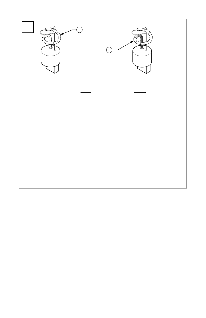
After extended operation, occasionally check for flash tube degradation. Should the flash tube
misfire, have a noticeable decrease in light output, glow continuously or darken to a point
beyond that shown in figure 1—it should be replaced.
High voltages are present inside the light assembly. Wait at least 5 minutes after shutting off the
power before servicing this unit.
To replace the flash tube, proceed as follows:
1. Disconnect power.
2. Remove the screw located at the bottom of the dome
3. Grasp the top of the dome and push down while turning the dome counter-clockwise
approximately 3/4-inch.
4. Gently lift the dome away. Ensure the gasket between the dome and base is not lost.
5. Grasp the flash tube by its base and pull it out of the socket, using a gentle “rocking”
motion. Insert the new flash tube.
6. Before replacing dome, ensure that the gasket is properly seated on the housing base.
Place the dome over the base, aligning the recesses inside the dome lip with the four pins
on the base. Push down on the dome and turn clockwise until it locks in place (approximately 3/4-inch)
7. Replace the screw in the bottom of the dome.
8. Test the light for proper operation.
B. PC Board Replacement.
High voltages are present inside the light assembly. Wait at least 5 minutes after shutting off the
power before servicing this unit.
1. Disconnect the power.
2. Remove the remove the screw located at the bottom of the dome
3. Grasp the top of the dome and push down while turning the dome counter-clockwise
approximately 3/4-inch.
4. Gently lift the dome away. Ensure that the gasket between the dome and base is not lost.
5. Remove the flash tube as described in paragraph II.A.5. Flash Tube Replacement.
6. Remove the power connector(s) from the P.C. board. When replacing older board assemblies,
the power connectors need to be adjusted to match the new assemblies. Included with the
replacement board is a power lead adaptor. Since some strobes are polarity sensitive,
connect matching colored wires together.
7. Remove the 6-32 screws, which secure the circuit board to housing base. On older DC units,
the #4 phillips head screw securing the power transistor must also be removed. Remove the
old circuit board. Place the new circuit board in position. Secure the circuit board in
position by installing two 6-32 screws at opposite corners of the circuit board.
8. Install the flash tube as described in paragraph II.A.5. Flash Tube Replacement.
-3-

9. Before replacing dome, ensure that the gasket is properly seated on the die-cast base. Place
the dome over the base, aligning the recesses inside the dome lip with the four pins on the
base. Push down on the dome and turn clockwise until it locks in place (approximately 3/4inch).
10. Replace the screw in the bottom of the dome.
11. Reassemble the light and test for proper operation.
C. Service.
The Federal factory will service your equipment or provide technical assistance with any
problems that cannot be handled locally.
Any units returned to Federal Signal for service, inspection, or repair must be accompanied by
a Return Material Authorization. This R.M.A. can be obtained from the local Distributor or
Manufacturer’s Representative.
At this time a brief explanation of the service requested, or the nature of the malfunction,
should be provided.
Address all communications and shipments to:
FEDERAL SIGNAL CORPORATION
Electrical Products Division
Service Department
2645 Federal Signal Drive
University Park, IL 60466-3195
D. Replacement Parts.
Description Part Number
Dome, Amber, Kit K8550320A
Dome, Blue, Kit K8550320A-01
Dome, Clear, Kit K8550320A-02
Dome, Green, Kit K8550320A-03
Dome, Red, Kit K8550320A-04
Dome, Magenta, Kit K8550320A-05
Flash Tube/Trigger Coil Assy. K8107177A
Fuse, 120 and 230-240 VAC units, K148A155A-01
1A, 250V
Circuit Board, 12-24VDC K2001202C
Circuit Board, 120VAC K200D866G
Circuit Board, 230-240VAC K200D866G-01
Circuit Board, Inrush Current, 24VDC K2001918A
-4-

III. UNDERWRITERS LABORATORIES WARNING EXPLANATION.
“Warning-Not to be used as a visual public mode alarm notification appliance”
WHAT DOES THIS MEAN?
Underwriters Laboratories uses two different standards to investigate and List visual signal
appliances. The first UL Standard for Safety is UL1971 - Signaling Devices for the Hearing
Impaired. This standard covers visual signaling devices intended for fire alarm systems to alert the
hearing impaired. The second UL Standard for Safety is UL1638 - Visual Signaling
Appliances-Private Mode Emergency and General Utility Signaling. While this standard may also
cover visual signal appliances, it does not include the determination of adequacy relative to alerting
hearing-impaired individuals in a fire alarm system.
To prevent misapplication of a visual signal appliance Listed to UL1638, UL determined it is the
manufacturer’s responsibility to warn the installer in the field and Authority Having Jurisdiction
(AHJ) of what would be an inappropriate use of the product. Therefore, manufactures whose
products Listed to UL1638 are required by Underwriters Laboratories to bear the warning,
“Warning - Not to be used as a visual public mode alarm notification appliance”.
“Public Operating Mode” and “Notification Appliance” as defined in the National Fire Alarm Code,
NFPA 72 is as follows:
Public Operating Mode - Audible or visible signaling to occupants or inhabitants of the area
protected by the fire alarm system.
Notification Appliance - A fire alarm system component such as a bell, horn, speaker, light, or
text display that provides audible, tactile, or visible outputs, or any combination thereof.
In other words, this device should not be used as a component of a commercial fire alarm system.
-5-

HOJA DE INSTRUCCIONES PARA LOS MODELOS FEDERAL FB2PST Y FB2PST-I (12-
24VCC, 24VCC, 120VCA Y 230-240VCA)
I. INSTALACIÓN.
MENSAJE DE SEGURIDAD PARA LOS INSTALADORES
AVISO
La instalación, el mantenimiento y el desecho de este producto se deben llevar a cabo de acuerdo con
los códigos y normas nacionales.
Es importante seguir todas las instrucciones enviadas con este producto. Este dispositivo debe ser
instalado por un electricista capacitado que esté totalmente familiarizado y que cumpla con todos
los códigos nacionales y locales del país de uso.
Este dispositivo se debe considerar como una parte del sistema de advertencia y no como el sistema
de advertencia total.
La elección del sitio para el montaje del dispositivo, sus controles y la ruta del cableado debe
realizarse bajo la dirección del ingeniero de instalaciones y el Ingeniero de seguridad. Además, a
continuación se detallan otras importantes instrucciones y precauciones sobre la seguridad, que
usted debe cumplir:
• Lea y entienda todas las instrucciones antes de instalar o de operar este equipo.
• No conecte esta luz al sistema mientras el mismo esté encendido.
• Después de la instalación, asegúrese de que todos tornillos estén apretados de forma adecuada.
• Después de la instalación, pruebe el sistema de luces para asegurarse que está funcionando
adecuadamente.
• Luego de finalizar la prueba, proporciónele una copia de esta de hoja instrucciones a todo el
personal que lo manejará.
• Establezca un procedimiento para revisar rutinariamente la instalación de las luces para
verificar su integridad y un funcionamiento adecuado.
El no cumplimiento con todas las precauciones e instrucciones de seguridad puede resultar en daño
a la propiedad, lesiones graves, o muerte para usted u otros.
A. General.
El Modelo FB2PST está disponible para 12-24Vcc, 120Vca, 50/60 Hz y 230-240Vac, 50/60 Hz.
El modelo FB2PST-I sólo está disponible en 24 VCC.
B. Desempaque.
Después de desempacar la unidad, examínela para verificar que no tenga daños que puedan
haber ocurrido en tránsito. Si el equipo ha sido dañado, no intente instalarlo o hacerlo
funcionar, preséntele un reclamo inmediatamente al transportista describiendo el alcance del
daño. Revise cuidadosamente todos los sobres, etiquetas de envío, etiquetas y talones de envío
antes de quitarlos o destruirlos.
C. Modelo FB2PST y FB2PST-I.
Las luces estroboscópicas Modelo FB2PST están diseñadas para ser montadas sobre una
superficie plana horizontal o vertical o en un tubo roscado NPT de 1/2 pulgada. Se puede
lograr un montaje sobre una superficie vertical con los lentes ubicados hacia arriba, utilizando
una ménsula de montaje de pared (Modelo LWMB2) o de esquina (Modelo LCMB2) de Federal
Signal, que se compra por separado.
1. Montaje sobre un tubo
El Modelo FB2PST se puede montar sobre un tubo de 1/2 pulgada. Los accesorios de
montaje y los detalles de instalación se le dejan al instalador.
AVISO
Para evitar que la conexión se afloje, apriete el montaje a una fuerza de torsión MÍNIMA de 5
pies-libra (6,8N m) después de enroscarlo en el tubo.
6-

2. Montaje sobre una superficie
a. Utilizando la junta como plantilla, trace los tres orificios de montaje y el orificio central
para montarlo sobre una superficie. Taladre un orificio de 3/16” (4,8 mm) de diámetro en
cada una de las tres marcas de montaje que trazó. Taladre o corte un orificio de 1” (25,4
mm) de diámetro en el centro para pasar los cables.
b. Coloque la luz sobre la junta y adósela sobre la superficie de montaje utilizando los
tornillos #8-32 proporcionados.
c. Remítase el párrafo E. para obtener información para realizar las conexiones eléctricas.
D. Conexiones eléctricas.
1. Modelos FB2PST 120 y 230-240 VCA.
No lo conecte al circuito de alimentación cuando este tiene corriente.
Las unidades de corriente alterna FB2PST se proporcionan con tres conductores (uno
negro, uno blanco, y uno verde/amarillo). Algunos modelos pueden tener los siguientes
colores alternativos: marrón en lugar de negro, y azul en lugar de blanco. Conecte el
conductor negro (o marrón) en el lado de la fase de la fuente de energía, el conductor blanco
(o azul) al lado común (neutro) de la fuente de energía, y el conductor verde/amarillo a la
descarga a tierra.
AVISO
Las unidades estroboscópicas de 120 y 230–240 VCA están diseñadas para funcionar tanto con
corrientes eléctricas de 50 como de 60 Hz. NO se requieren modificaciones especiales para los dos
tipos de frecuencias de línea de CA diferentes.
2. Modelo FB2PST 12-24VCC y FB2PST-I 24VCC.
La unidad de corriente continua, Modelo FB2PST se proporciona con dos conductores (uno
rojo y uno negro). Conecte el conductor rojo (+) a la terminal de la fuente de energía positiva
y el negro (-) a la terminal de la fuente de energía negativa.
AVISO
La polaridad DEBE ser tenida en cuenta para el funcionamiento.
II.MANTENIMIENTO.
MENSAJE DE SEGURIDAD PARA LOS INSTALADORES
Debajo están listadas algunas instrucciones y precauciones importantes sobre la seguridad, que
usted debe cumplir:
• Lea y entienda todas las instrucciones antes de operar este sistema
• Cualquier mantenimiento que se le realice al sistema de luz debe llevarse a cabo con la energía
apagada.
• Cualquier mantenimiento que se le realice al sistema de luz debe ser llevado a cabo por un
electricista capacitado y de acuerdo con todos los códigos y estándares nacionales y locales del
país de uso.
• Nunca altere la unidad en forma alguna.
• La placa con el nombre del producto, que puede contener información de advertencia u otra
información importante para el personal de mantenimiento, NO DEBE ser ocultada en forma
alguna. Asegúrese de que la placa con el nombre del producto permanezca legible cuando se
pinten las piezas exteriores.
El no cumplimiento con todas las precauciones e instrucciones de seguridad puede resultar en daño
a la propiedad, lesiones graves, o muerte para usted u otros.
-7-

A. Reemplazo del tubo de intermitencia.
A medida que las luces estroboscópicas se utilizan, los tubos de intermitencia comienzan a
oscurecerse, provocando una disminución en la entrega de luz. Este oscurecimiento es
característico de los tubos de intermitencia. El oscurecimiento comenzará cerca de la base del
tubo y avanzará hacia arriba. Además los tubos de intermitencia después de cierta duración
comienzan a dispararse erróneamente (no se disparan en forma periódica).
Luego de un funcionamiento prolongado, verifique ocasionalmente la degradación del tubo de
intermitencia. Si el tubo de intermitencia se dispara erróneamente, tiene una disminución
notable en la entrega de luz, brilla continuamente o se oscurece hasta un punto mayor del que
se muestra en la figura 1, es necesario reemplazarlo.
Existen voltajes altos dentro del ensamblaje de la luz. Espere al menos 5 minutos después de
cortar la fuente de energía para realizarle el mantenimiento a esta unidad.
Para reemplazar el tubo de intermitencia, proceda de la siguiente manera:
1. Desconecte la fuente de energía.
2. Quite el tornillo ubicado en la parte inferior del domo
3. Tome la parte superior del domo y empuje hacia abajo mientras lo gira en sentido
antihorario aproximadamente 3/4 de pulgada.
4. Levante el domo con mucho cuidado. Asegúrese de que la junta ubicada entre el domo y la
base no se pierda.
5. Tome el tubo de intermitencia por su base y tire del mismo, con un suave movimiento
“oscilante”, para quitarlo del portalámparas. Inserte el nuevo tubo de intermitencia.
6. Antes de volver a colocar el domo, asegúrese de que la junta esté adecuadamente ubicada
sobre la base de la caja. Coloque el domo nuevamente sobre la base, alineando los encastres
dentro del reborde del domo con las cuatro clavijas de la base. Empuje el domo hacia abajo y
gire en sentido horario hasta que se trabe en su lugar (aproximadamente 3/4 de pulgada)
7. Vuelva a colocar los tornillos en la parte inferior del domo.
8. Pruebe la luz para verificar que está funcionando correctamente.
B. Reemplazo de la placa de PC.
Existen voltajes altos dentro del ensamblaje de la luz. Espere al menos 5 minutos después de
cortar la fuente de energía para realizarle el mantenimiento a esta unidad.
1. Desconecte la fuente de energía.
2. Quite el tornillo ubicado en la parte inferior del domo
3. Tome la parte superior del domo y empuje hacia abajo mientras lo gira en sentido
antihorario aproximadamente 3/4 de pulgada.
4. Levante el domo con mucho cuidado. Asegúrese de que la junta ubicada entre el domo y la
base no se pierda.
5. Quite el tubo de intermitencia como se describe en el párrafo II.A.5. Reemplazo del tubo de
intermitencia.
6. Quite el/los conector(es) de energía de la placa de P.C. Cuando reemplace ensamblajes de
placas anteriores, los conectores de energía se deben ajustar para que se correspondan con
los ensamblajes nuevos. Con la placa de remplazo se encuentra un adaptador de conductor
de energía. Como algunas luces estroboscópicas son sensibles a la polaridad, conecte los
colores iguales juntos.
7. Quite los tornillos 6-32, que aseguran la placa del circuito a la base de la carcasa. En
unidades de CC anteriores, los tornillos phillips #4 que aseguran el transistor de energía
-8-

también se deben quitar. Quite la placa del circuito anterior. Coloque la nueva placa del
circuito en posición. Asegure la placa del circuito en posición instalando dos tornillos 6-32
en esquinas opuestas en la placa del circuito.
8. Instale el tubo de intermitencia como se describe en el párrafo II.A.5. Remplazo del tubo de
intermitencia.
9. Antes de reemplazar el domo, asegúrese de que la junta esté adecuadamente colocada sobre
la base de la caja. Coloque el domo nuevamente sobre la base, alineando los encastres
dentro del reborde del domo con las cuatro clavijas de la base. Empuje el domo hacia abajo y
gire en sentido horario hasta que se trabe en su lugar (aproximadamente 3/4 de pulgada)
10. Vuelva a colocar los tornillos en la parte inferior del domo.
11. Vuelva a armar la luz y pruébela para verificar que está funcionando correctamente.
C. Servicio de mantenimiento.
La fábrica Federal le realizará el mantenimiento de su equipo o le proporcionará asistencia
técnica con cualquier problema que no pueda ser manejado en forma local.
Cualquier unidad que sea devuelta a Federal Signal para mantenimiento, inspección, o
reparación debe estar acompañada de una Autorización de devolución de material (R.M.A.).
Esta R.M.A. se puede obtener del distribuidor local o del representante del fabricante.
En ese momento, se deberá proporcionar una breve explicación del mantenimiento solicitado, o
de la naturaleza del mal funcionamiento.
Dirija todas las comunicaciones y envíos a:
FEDERAL SIGNAL CORPORATION
Electrical Products Division
Service Department
2645 Federal Signal Drive
University Park, IL 60466-3195
D. Piezas de reemplazo.
Descripción Parte No.
Domo, Ambar, juego K8550320A
Domo, Azul, juego K8550320A-01
Domo, Incoloro, juego K8550320A-02
Domo, Verde, juego K8550320A-03
Domo, Rojo, juego K8550320A-04
Domo, Magenta, juego K8550320A-05
Tubo de intermitencia/Montaje de bobina disparadora K8107177A
Fusible, unidades de 120 y 230-240 VCA, 1A, 250V K148A155A-01
Placa de circuito, 12-24 VCC K2001202C
Placa de circuito, 120 VCA K200D866G
Placa de circuito, 230-240 VCA K200D866G-01
Tablero de circuito, corriente inicial, 24 VCC K2001918A
-9-

III. EXPLICACIÓN DE ADVERTENCIA DE UNDERWRITERS LABORATORIES.
“Advertencia-No debe usarse como un aparato de notificación de alarma visual en modo
público”
¿QUÉ SIGNIFICA ESTO?
Underwriters Laboratories usa dos normas diferentes para investigar y listar aparatos de
señalización visual. La primera norma UL para seguridad es la UL1971 - Dispositivos de
señalización para personas con discapacidad auditiva. Esta norma cubre dispositivos de
señalización visual diseñados para sistemas de alarma de incendio para alertar a personas con
discapacidad auditiva. La segunda norma UL para seguridad es la UL1638 - Aparatos de
señalización visual-Emergencia en modo privado y Señalización de utilidad general. Aunque esta
norma también puede cubrir aparatos de señalización visual, no incluye la determinación de la
idoneidad en relación con la puesta en alerta a personas con discapacidad auditiva en un sistema de
alarma de incendio.
Para evitar la mala aplicación de un aparato de señalización visual listado en UL1638, UL decidió
que es responsabilidad del fabricante advertir al instalador en el campo y a la autoridad competente
lo que sería un uso inapropiado del producto. En consecuencia, Underwriters Laboratories requiere
que los fabricantes cuyos productos estén listados en UL1638, incluyan el aviso, “Advertencia - No
debe usarse como un aparato de notificación de alarma visual en modo público”.
Las definiciones de “Modo de operación pública” y “Aparato de notificación” de acuerdo con el Código
Nacional de alarmas de incendio, NFPA 72, son las siguientes:
Modo de operación pública - Señalización audible o visual para los ocupantes o habitantes del
área protegida por el sistema de alarma de incendio.
Aparato de notificación - Componente de un sistema de alarma de incendio como una campana,
una bocina, un altavoz, una luz, o una pantalla de texto, que proporciona una salida auditiva, táctil,
o visible, o cualquier combinación de los mismos.
En otras palabras, este dispositivo no debería usarse como componente de un sistema comercial de
alarma de incendio.
-10-

FEUILLET D’INSTRUCTIONS POUR LES LAMPES FIREBALL® FEDERAL MODÈLES
FB2PST ET FB2PST-I (12-24 V.C.C., 24 V.C.C., 120 V.C.A., ET 230-240 V.C.A.)
I. L’INSTALLATION.
MESSAGE DE SÉCURITÉ POUR LES INSTALLATEURS
NOTE
L’installation, l’entretien et l’élimination de ce produit doivent se faire conformément aux normes et
aux codes nationaux.
Il est important de suivre toutes les instructions expédiées avec ce produit. Ce dispositif doit être
installé par un électricien bien formé qui connaît tous les codes nationaux et locaux dans le pays
d’usage et qui les respecte.
Ce dispositif doit être considéré comme faisant partie d’un système d’avertissement et non pas
comme l’ensemble du système.
Le choix de l’emplacement de montage de ce dispositif, ses contrôles et l’acheminement du câblage
doivent se faire sous la direction de l’ingénieur de l’installation et de l’ingénieur de sécurité. En
outre, vous trouverez ci-après une liste de certaines instructions et précautions de sécurité
importantes à suivre :
• Lisez attentivement et comprenez bien toutes les instructions avant d’installer ou de faire
fonctionner cet équipement.
• Ne branchez pas cette lampe au système lorsque le courant n’est pas coupé.
• Après l’installation, assurez-vous que toutes les vis de fixation sont bien resserrées.
• Après l’installation, assurez-vous de tester le système d’éclairage pour vérifier qu’il fonctionne
correctement.
• Après la fin du test, fournissez une copie de ce feuillet d’instructions à tout le personnel des
opérations.
• Établissez une procédure de vérification de routine de l’installation d’éclairage pour vous
assurer de son intégrité et de son bon fonctionnement.
Le fait de ne pas suivre toutes les précautions et instructions de sécurité peut provoquer des
dommages à la propriété, des blessures graves voire la mort pour vous et pour d’autres personnes.
A. Généralités.
Le modèle FB2PST est disponible pour 12-24 v.c.c., 120 v.c.a., 50/60 Hz et 230-240 v.c.a.,
50/60 Hz. Le modèle FB2PST-I est uniquement disponible en 24Vdc.
B. Déballage.
Après avoir déballé l’unité, examinez-la pour voir s’il y a eu des dommages pendant le
transport. Si l’équipement est endommagé, n’essayez pas de l’installer ou de le faire fonctionner. Déposez immédiatement une réclamation auprès du transporteur en indiquant la portée
des dommages. Vérifiez avec soin toutes les enveloppes, les étiquettes d’expédition et les
étiquettes avant de les retirer ou de les détruire.
C. Modèle FB2PST et FB2PST-I.
Les lampes stroboscopiques de modèle FB2PST sont conçues pour être installées sur une
surface à plat, horizontale ou verticale ou sur un tuyau fileté NPT de 1/2 po (1,27 cm). Vous
pouvez l’installer sur une surface verticale, lentille vers le haut en utilisant une fixation de
montage de Federal Signal pour le mur (Modèle LWMB2) ou pour le coin (Modèle LCMB2).
1. Montage sur tuyau
Le modèle FB2PST peut s’installer sur un tuyau de 1/2 po (1,27 cm). La quincaillerie et les
détails d’installation sont laissés à la discrétion de l’installateur.
NOTE
Pour éviter que les connexions se desserrent, resserrez l’appareil à un couple MINIMUM de
5 pi-lb (6,8 N m) après l’avoir enfilé sur le tuyau.
-11-

2. Montage en surface
a. Utilisez le joint d’étanchéité statique comme gabarit, marquez trois trous de montage et
un trou central pour la surface d’installation. Percez un trou de 3/16 po (4,8 mm) de
diamètre à chacune des marques de montage indiquées. Percez ou perforez un trou de 1
po (25,4 mm) de diamètre au centre pour les fils.
b. Placez la lampe sur le joint d’étanchéité statique et fixez à la surface de montage avec les
vis 8-32 fournies.
c. Reportez-vous au paragraphe E pour les connexions électriques.
D. Connexions électriques.
1. Modèles FB2PST 120 et 230-240 v.c.a.
Ne connectez pas les fils si le courant n’est pas coupé.
Les unités à courant alternatif FB2PST sont fournies avec trois fils (un noir, un blanc et un
vert/jaune) pour les appareils à c.a. Certains modèles ont les couleurs alternatives
suivantes : brun au lieu de noir et bleu au lieu de blanc. Connectez le fil noir (ou brun) au
côté phase de la source de courant, le fil blanc (ou bleu) au côté commun (neutre) de la
source de courant et le fil vert/jaune à la masse.
NOTE
Les appareils stroboscopiques de 120 et de 230-240 v.c.a. sont conçus pour fonctionner sur un
courant de 50 et de 60 Hz. Il ne faut PAS de modifications spéciales pour les deux fréquences
différentes de lignes à c.a.
2. Modèle FB2PST 12-24 v.c.c. et FB2PST-I 24 v.c.c.
Le modèle FB2PST à courant direct est doté de deux fils (un rouge et un noir). Connectez le
fil rouge (+) à la borne de source de courant positif et noir (-) à la borne de source de courant
négatif.
NOTE
La polarité DOIT être observée pour l’opération.
II.ENTRETIEN.
MESSAGE DE SÉCURITÉ POUR LE PERSONNEL D’ENTRETIEN
Vous trouverez ci-après une liste de certaines instructions et précautions de sécurité importantes à
suivre :
• Lisez attentivement et comprenez bien toutes les instructions avant de faire fonctionner ce
système.
• Ne faites pas l’entretien de ce système d’éclairage si le circuit est sous tension.
• Tout entretien de ce système d’éclairage doit être effectué par un électricien bien formé qui
connaît tous les codes nationaux et locaux dans le pays d’usage et qui les respecte
• Ne modifiez jamais cet appareil de quelque façon que ce soit.
• Les plaques signalétiques contenant des informations de mise en garde et autres informations
importantes pour le personnel d’entretien ne doivent PAS être obscurcies de quelque façon que ce
soit. Assurez-vous que la plaque reste lisible lorsque l’extérieur de l’enceinte est peint.
Le fait de ne pas suivre toutes les précautions et instructions de sécurité peut provoquer des
dommages à la propriété, des blessures graves voire la mort pour vous et pour d’autres personnes.
A. Remplacement du tube à éclats.
Au fur et à mesure où les lampes stroboscopiques sont utilisées, les tubes à éclats commencent
à foncer provoquant une réduction d’éclairage. Cet assombrissement est caractéristique des
tubes à éclats et commence près de la base du tube pour ensuite monter. De même, les tubes à
éclats plus vieux ont parfois tendance à avoir des ratés (ne pas s’allumer parfois).
-12-

Après une utilisation prolongée de l’appareil, vérifiez à l’occasion la dégradation du tube à
éclats. Si le tube connaît des ratés, une réduction appréciable de la sortie d’éclairage, un éclat
continuel ou un obscurcissement dépassant ce qui est indiqué sous la figure 1 - il faut le
remplacer.
Il y a de hautes tensions à l’intérieur du montage de la lampe, attendez au moins 5 minutes
après avoir coupé le courant avant d’en faire l’entretien ou les réparations.
Pour remplacer le tube à éclats, procédez comme suit :
1. Coupez le courant.
2. Retirez la vis qui se trouve au bas du globe.
3. Agrippez le dessus du globe et poussez vers le bas tout en tournant le globe dans le sens
contraire des aiguilles d’une montre d’environ 3/4 pouce (19,05 mm).
4. Soulevez délicatement le globe. Assurez-vous que le joint d’étanchéité statique entre le
globe et la base n’est pas perdu.
5. Agrippez le tube à éclats par sa base et tirez pour le sortir de sa douille en utilisant un
léger mouvement de « bascule ». Insérez le nouveau tube.
6. Avant de remplacer le globe, assurez-vous que le joint d’étanchéité est bien placé sur la
base de l’enceinte. Placez le globe sur la base en alignant les rainures à l’intérieur de la
lèvre du globe avec les quatre goupilles sur la base. Poussez vers le bas sur le globe et
tournez dans le sens des aiguilles d’une montre jusqu’à ce que le tout se verrouille en place
(environ 3/4 de pouce (1,905 cm).
7. Replacez la vis au bas du globe.
8. Testez l’éclairage pour vous assurer que tout fonctionne correctement.
B. Remplacement de la plaquette PC.
Il y a de hautes tensions à l’intérieur du montage de la lampe, attendez au moins 5 minutes
après avoir coupé le courant avant d’en faire l’entretien ou les réparations.
1. Coupez le courant.
2. Retirez la vis qui se trouve au bas du globe.
3. Agrippez le dessus du globe et poussez vers le bas tout en tournant le globe dans le sens
contraire des aiguilles d’une montre d’environ 3/4 pouce (19,05 mm).
4. Soulevez délicatement le globe. Assurez-vous que le joint d’étanchéité statique entre le
globe et la base n’est pas perdu.
5. Retirez le tube à éclats tel que décrit sous la paragraphe II.A.5. Remplacement du tube à
éclats.
6. Retirez le(s) connecteur(s) d’alimentation de la plaquette à circuits imprimés. En remplaçant la vieille plaquette, il faut ajuster les connecteurs d’alimentation selon le nouvel
assemblage. Vous trouverez avec la plaquette de rechange un adaptateur de fil d’alimentation. Puisque certaines lampes stroboscopiques sont sensibles à la polarité, connectez les
fils de couleur complémentaire ensemble.
7. Retirez les vis 6-32 qui retiennent la plaquette à la base de l’enceinte. Pour les unités à c.c.
plus vieilles, la vis à tête phillips #4 retenant le transistor de puissance doit aussi être
enlevé. Retirez l’ancienne plaquette et placez la nouvelle en position. Fixez la plaquette en
installant deux vis 6-32 dans les coins opposés de la plaquette.
8. Installez le tube à éclats tel que décrit sous le paragraphe II.A.5 Remplacement du tube à
éclats.
-13-

9. Avant de replacer le globe, assurez-vous que le joint d’étanchéité statique est bien installé
sur la base de l’enceinte. Placez le globe sur la base en alignant les rainures à l’intérieur de
la lèvre du globe avec les quatre ergots de la base. Poussez le globe vers le bas et tournez
dans le sens des aiguilles d’une montre jusqu’à ce qu’il se verrouille en place (environ 3/4 po
(19,05 mm).
10. Replacez la vis au bas du globe.
11. Remontez la lampe et testez pour vous assurer qu’elle fonctionne correctement
C. Service.
L’usine Federal Signal fera l’entretien et la réparation de votre équipement ou fournira l’aide
technique voulue avec tout problème qui ne peut être résolu localement.
Toutes les unités retournées à Federal Signal pour entretien, inspection ou réparations
doivent être accompagnées d’une autorisation de retour du matériel. Cette autorisation
s’obtient du distributeur local ou d’un représentant du fabricant.
Il faudrait aussi ajouter une brève explication des services requis ou de la nature de la
défaillance.
Adressez toutes communications et expéditions à :
FEDERAL SIGNAL CORPORATION
Electrical Products Division
Service Department
2645 Federal Signal Drive
University Park, IL 60466-3195
D. Pièces de rechange.
Description Numéro de pièces
Globe, ambré, kit K8550320A
Globe, bleu, kit K8550320A-01
Globe, transparent, kit K8550320A-02
Globe, vert, kit K8550320A-03
Globe, rouge, kit K8550320A-04
Globe, magenta, kit K8550320A-05
Tube à éclats/serpentin de déclenchement K8107177A
Fusible, unités de 120 et 230-240 v.c.a., 1A, 250V K148A155A-01
Plaquette de circuits, 12-24 v.c.c K2001202C
Plaquette de circuits, 120 v.c.a. K200D866G
Plaquette de circuits, 230-240 v.c.a. K200D866G-01
Carte de circuits imprimés, courant d’appel, 24VDC K2001918A
-14-

III. EXPLICATION DE L’AVERTISSEMENT DE UNDERWRITERS LABORATORIES.
“Avertissement-Ne pas utiliser comme appareil de signal d’alarme mode public visuel”
QUE VEUT DIRE CECI ?
Underwriters Laboratories utilise deux normes différentes pour examiner et lister les appareils de
signaux visuels. La première Norme UL pour la Sécurité est l’UL1971 – Dispositifs de Signaux pour
les Malentendants. Cette norme couvre les dispositifs de signaux visuels que comportent les systèmes d’alarme d’incendie pour alerter les malentendants. La deuxième Norme UL pour la Sécurité
est l’UL1638 – Appareils de Signaux Visuels-Signaux d’Urgence Mode Privé et d’Usage Général.
Bien que cette norme puisse aussi couvrir les appareils de signaux visuels, elle n’inclut pas l’établissement d’une conception adéquate pour alerter les personnes malentendantes avec un système
d’alarme d’incendie.
Pour éviter l’utilisation erronée d’un appareil de signaux visuels listé sous UL1638, l’UL stipule
qu’il incombe au fabricant d’avertir l’installateur sur le site et l’Instance de Juridiction Compétente
(Authority Having Jurisdiction) (AHJ) sur ce que serait une utilisation non appropriée du produit.
En conséquence, les fabrications dont les produits sont listés sous UL1638 sont tenue par
Underwriters Laboratories de porter l’avertissement, “Avertissement –Ne pas utiliser comme appa-
reil de signal d’alarme mode public visuel”.
“Mode Opératoire Public” et “Appareil de Signal” sont définis dans le Code National d’Alarme d’Incendie, NFPA 72, comme suit :
Mode Opératoire Public – Signal audible ou visible pour les occupants ou habitants de la zone
protégée par le système d’alarme d’incendie.
Appareil de Signal – Un composant de système d’alarme d’incendie tel qu’une sonnerie, une
sirène, un haut-parleur, un voyant ou un affichage de texte émettant des signaux audibles, tactiles
ou visibles, ou leur combinaison.
En d’autres termes, ce dispositif ne doit pas être utilisé comme composant d’un système d’alarme
d’incendie commercial.
-15-
1
A
B
290A3055
English
A. New flash tube
B. Used flash tube tends to discolor
in areas shown and should be
replaced.
Español
A. Tubo de destellos luminosos nuevo
B. El tubo de destellos luminosos
usado tiende a descolorarse en las
áreas indicadas y debe
reemplazarse.
Français
A. tube à éclats neuf
B. Un tube à éclats usé a tendance à se
décolorer à certains endroits et doit
être remplacé.
-16-


256896P
REV. P Printed 9/04
Printed in U.S.A.
 Loading...