

Page 1

FEDERAL SIGNAL CORPORATION
Electrical Products Division
INSTALLATION INSTRUCTIONS
MODEL 400 SERIES LIGHTS
256A424G
REV. G 401
Printed in U.S.A.
FOR
SAFETY MESSAGE TO INSTALLERS
It is important to follow all instructions shipped with
this product. This device is to be installed by a trained
electrician who is thoroughly familiar with the National
Electrical Code and will follow the NEC Guidelines as
well as local codes.
The selection of the mounting location for the device,
its controls and the routing of the wiring is to be
accomplished under the direction of the facilities
engineer and the safety engineer. In addition, listed
below are some other important safety instructions and
precautions you should follow:
• Read and understand all instructions before installing
or operating this equipment.
• Do not connect this light to the system when power is
on.
• After installation, test the light system to ensure that it
is operating properly.
• After testing is complete, provide a copy of this
instruction sheet to all operating personnel.
• Establish a procedure to routinely check the light
system for proper activation and operation.
Failure to follow all safety precautions and instructions
may result in property damage, serious injury, or death
to you or others.
I. GENERAL.
A Model 350 Vibratone Horn can be installed in the
lower housing of a Model 400 Series Light. It is
usually more convenient to install the audible device
in the light before attaching the light to the mounting
surface. Therefore, it is recommended that the audible
device be installed (if applicable) before proceeding.
II. UNPACKING.
After unpacking the unit, examine it for damage that
may have occurred in transit. If the equipment has
been damaged, do not attempt to install or operate it.
File a claim immediately with the carrier stating the
extent of the damage. Carefully check all envelopes,
shipping labels and tags before removing or destroying them. Ensure that the parts listed in the KIT
CONTENTS LIST are included in the packing carton.
III. KIT CONTENTS LIST.
Qty. Description
2 Hex. Head Mach.Screws, 1/4-20
2 Allen Head Set Screws, Cone Pt.
2 6-32 x 3/16" Hex Screws, Taptite
2 Nut, KEPS, 1/4-20
1 Cover Plate, Mounting Adapter
1 Cover, Self-Adhesive
1 Plate, Mounting Adapter
1 Bracket, Wall/Ceiling Mounting
1 Grommet
IV. INSTALLATION.
SAFETY MESSAGE TO
MAINTENANCE PERSONNEL
Listed below are some important safety instructions
and precautions you should follow:
• Read and understand all instructions before operating
this system.
• Any maintenance to the light system must be done
with the power turned off.
• Any maintenance to the light system must be performed by a trained electrician in accordance with
NEC Guidelines and local codes.
• Never alter the unit in any manner. Safety in hazardous locations may be endangered if additional openings or other alterations are made in units specifically
designed for use in these locations.
• The nameplate, which may contain cautionary or
other information of importance to maintenance
personnel, should not be obscured if exterior of
housings used in hazardous locations are painted.
Failure to follow all safety precautions and instructions may result in property damage, serious injury, or
death to you or others.
Model 400 Series Lights can be mounted using any
one of three methods; flat surface mounted on a wall
or other vertical surface, on a 4" x 4" electrical box, or
flat surface mounted on a ceiling.
Page 2
A.Flat Surface (External Conduit) Mount.
1.See figure 1. Drill a 7/8" hole in the wall/ceiling
mounting bracket, as indicated in the figure. Use
caution to avoid damaging the bracket.
2.Install a user-supplied 1/2" conduit fitting into the
hole that was drilled in step 1.
3.Insert the nylon grommet in the large center hole
in the side of the light assembly main frame
casting, as shown in figure 2.
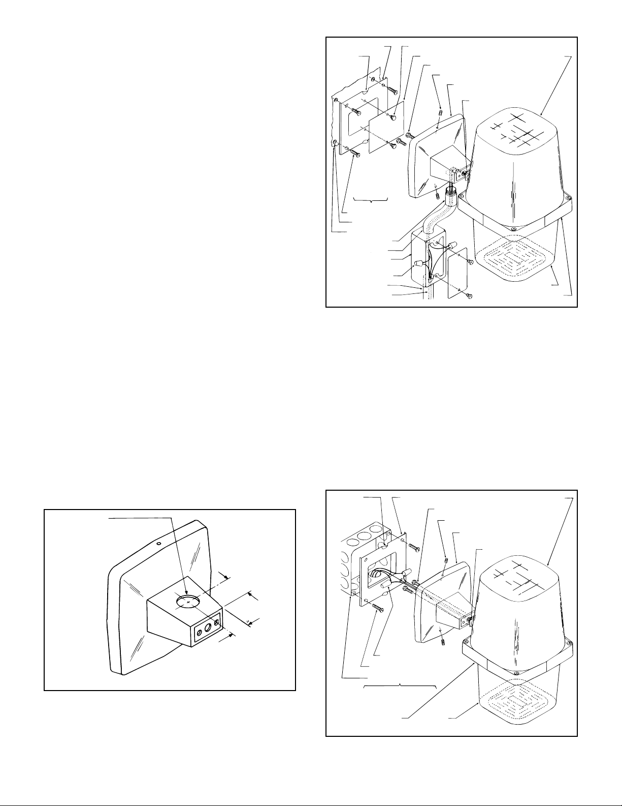
4.See figure 2. Attach the wall/ceiling mounting
bracket to the main frame casting, using two 1/4"20 x 1/2" hex head machine screws (supplied),
making sure that all wiring from the interior of
the light passes through the large center hole in
the end of the bracket. Route the wiring through
the conduit fitting that was installed in step 2.
5.Start the 10-32 x 3/4" cone point set screws in the
threaded holes in the upper andlower edges of the
wall/ceiling mounting bracket.
6.Attach the cover plate to the adapter plate, using
the two 6-32 x 316" self-tapping screws supplied.
7.Attach the adapter plate to the mounting surface,
using the appropriate user-supplied hardware, as
indicated in figure 3.
8.Place the light/mounting bracket assembly over
the adapter plate and tighten the two cone point
set screws, ensuring that the screws engage the
two dimples in the adapter plate.
CAUTION
DO NOT make electrical splices within the wall/ceiling
mounting bracket.
Adapter plate (1)
Dimples
Top &
bottom
Customer
supplied
Mtg. screws (4)
Anchors (4)
Supporting wall
1/2" Connector
1/2" Conduit
1/2"Condulet
(Make connections here)
Wire nuts (2)
1/2" Conduit
Power supply
6-32 screws hex hd. slf tap (2)
Cover plate (1)
1/4-20 screws hex hd. (2)
10-32 Set screws allen hd. (2)
Mounting bracket (1)
(wall/ceiling mtg.)
Grommet
290B1506
Lexan dome
Housing
Main mounting frame
Figure 2.
WARNING
DO NOT connect wires when power is applied.
9.Using the wires extending through the conduit
fitting as a guide, determine the length of the
conduit necessary for the installation, as indicated
in figure 3.
10.Install conduit and a condulet box (both usersupplied), as indicated. Splice the light leads to
the power leads in the condulet box. Connect the
green light lead (ground) to the condulet box by
the most convenient means. Insulate all splices.
7/8" Dia. hole
drilled by customer,
to accept 1/2"
conduit connector.
290A1504
Figure 1.
1- 3/16" approx.
7/8"
approx.
Dimples
Top & bottom
Wire nuts (2)
Mounting screws (2)
4 x 4 Electrical box (1)
Customer supplied
Main mounting frame
Adapter plate (1)
1/4-20 Screws hex hd. (2)
Housing
Figure 3.
Lexan dome
10-32 Set screws allen hd. (2)
Mounting bracket (1)
(wall/ceiling mtg.)
Grommet
290B1505
Page 3

B.Electrical Box Mount.
1.Install a 4" x 4" electrical box conduit and wiring,
as necessary (all user-supplied).
2.Insert the nylon grommet in the large center hole
in the side of the light assembly main frame
casting, as shown in figure 2.
3.See figure 3. Attach the wall/ceiling mounting
bracket to the main frame casting, using the two
1/4"-20 x 1/2" hex head screws (supplied). Make
sure that all wiring from the interior of the light
passes through the large center hole in the end of
the bracket.
4.Install the adapter plate (supplied) on the 4" x 4"
electrical box, using the appropriate user-supplied
hardware.
5.Start the two 10-32 x 3/4" cone point set screws
in the threaded holes in the upper and lower edges
of the wall/ceiling mounting bracket.
6.Connect the green wire (ground) to the 4" x 4"
electrical box.
CAUTION
DO NOT make electrical splices within the mounting
bracket.
WARNING
DO NOT connect wires when power is applied.
7.Splice the light wires and audible device wires (if
applicable) to the electrical supply wires in the
electrical box.
1. Remove the four slotted housing fastening nuts
and lift the lower housing from the light assembly.
2. Remove the grille cover plate from the bottom of
the housing by removing the four 6-32 KEPS nuts
and washers at the bottom of the housing.
3. Install the nylon grommet in the center hole in the
bottom of the lower housing.
4. Route the light supply wires through the grommet
that was installed in step 3.
5. Attach the wall/ceiling mounting bracket to the
lower housing using two 1/4"-20 x 1/2" hex head
machine screws and KEPS nuts (supplied).
6. Apply the self-adhesive cover over the holes on
the side of the main frame casting.
7. Reassemble the light following steps 1 and 2 in
reverse order.
8. Install the light on the ceiling following the
procedure in paragraph IV.A. or IV.B. of this
sheet, as appropriate.
4 x 4 Electrical box (1)
Wire nuts (2)
Mounting screws (2)
Customer supplied
1/4-20 screws hex hd. (2)
Moutnig bracket (1)
(wall/ceiling mtg.)
Dimples
(left & right)
Adapter plate (1)
Grommet (1)
8.Place the assembled light and mounting bracket
over the adapter plate and tighten the two cone
point set screws. Make sure that the screws
engage the two dimples in the adapter plate.
C.Ceiling Mount.
Model 400 Series Light can be mounted flat on a
ceiling or on a 4" x 4" electrical box. Both of these
mounting methods are variations on those methods
already described. However, the wall/ceiling mount
ing bracket must be attached to the lower housing
of the light. If an audible device was installed, the
mounting bracket should be attached to the lower
housing of the light. If the bracket is already
attached, disregard the procedure in this paragraph
and proceed directly to paragraph IV.A. or IV.B. of
this sheet, as appropriate. However, if it is necessary to attach the bracket to the light, proceed as
follows (see figure 4):
10-32 Set
screws allen
hd. (2)
6-32 Nuts,
housing
fastening (4)
Main
mounting
frame
290B1507
Figure 4.
Housing (1)
1/4-20 Hex nuts
ext. keps (2)
Cover (1)
(Self adhesive)
Lexan dome (1)
Page 4

V. SERVICE.
VI. REPLACEMENT PARTS LIST.
The Federal factory will service your equipment or
provide technical assistance with any problems that
cannot be handled locally.
Any units returned to Federal Signal for service,
inspection, or repair must be accompanied by a
Return Material Authorization. This R.M.A. can be
obtained from the local Distributor or Manufacturer’s
Representative.
At this time a brief explanation of the service requested, or the nature of the malfunction, should be
provided.
Address all communications and shipments to:
Service Department
Electrical Products Division
Federal Signal Corporation
2645 Federal Signal Drive
University Park, IL 60466-3195
Description Part Number
Dome, Lexan, Red K8547C001A-01
Dome, Lexan, Blue K8547C001A-03
Dome, Lexan, Amber K8547C001A-04
Dome, Lexan, Clear K8547C001A-05
Lens, Fresnel, Glass K8248C004A-04
Strobe Tube K8422A420B
Lamp K8107181A
Interior Lens, 400ST K8248C004E-04
PC Assembly , 400ST K200D825C
 Loading...