

Model 371DST Commander
Strobe Lights for
Hazardous Locations
Installation and
Maintenance Manual
®
256A504H
REV. H1 114
Printed in USA.
français...............page 8
español...............página 15

blank page

Installation and Service Instructions for Commander®
Model 371DST Strobe Lights
for Use in Hazrdous Locations
Safety Message to Installers,
Users and Maintenance Personnel
This equipment is suitable for use in Class I, Division 2, Groups A, B, C and D; Class II, Division 2;
Class 3 or non-hazardous locations only.
It is important to follow all instructions shipped with this product. This device is to be installed by a trained
electrician who is thoroughly familiar with the National Electric Code/Canadian Electric Code and will follow
the NEC/CEC Guidelines as well as local codes.
The selection of mounting location for the device, its controls and the routing of the wiring is to be
accomplished under the direction of the facilities engineer and the safety engineer. In addition, listed below
are some other important safety instructions and precautions you should follow:
• Read and understand all instructions before installing or operating this equipment.
• To reduce the risk of ignition of hazardous atmospheres, disconnect the fixture from the supply circuit
before opening. Keep tightly closed when in operation.
• The strobe housing is not be used as a raceway for through branch circuit conductors.
• After installation, ensure that the threaded dome ring joint is fully engaged.
• After installation, test the light system to ensure that it is operating properly.
• After testing is complete, provide a copy of this instruction sheet to all operating personnel.
• Establish a procedure to routinely check the light installation for integrity and proper
operation.
Failure to follow all safety precautions and instructions may result in property damage, serious injury, or
death to you and others.
I. INSTALLATION
A. Unpacking.
After unpacking the light, examine it for damage that may have occurred in transit. If the equipment has
been damaged, do not attempt to install or operate it. File a claim
the extent of the damage. Carefully check all envelopes, shipping labels, and tags before removing or
destroying them.
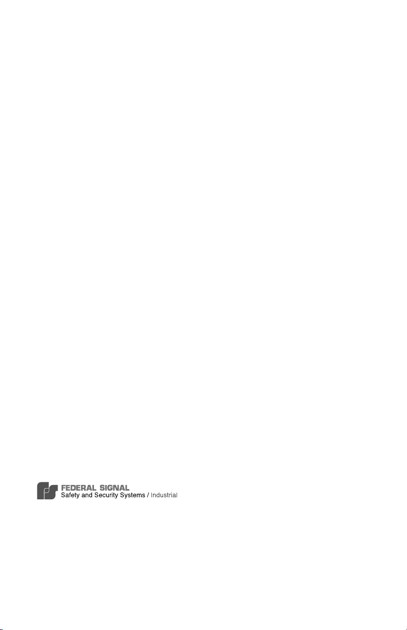
B. Mounting (see Figure 1).
CAUTION
To reduce the risk of fire or explosion, do not install in hazardous location if the operating
temperature exceeds the hazardous atmosphere’s ignition temperature. Refer to the product
nameplate for operating temperature markings.
The Model 371DST lights are designed for mounting on a flat horizontal surface or on a 1” NPT
pipe. For surface mounting on solid substrates, a separately purchased Model 371BRCKT (3-point
mounting bracket) may be used. When using Model 371BRCKT, the bottom 1” NPT conduit entry
of the light must be plugged with the 1” NPT close-up plug provided with the kit. If conduit side
entry is to be used, disassemble light as described in section ID.1 and remove knockout with a
blunt tool prior to mounting light. Use a file to remove excess flash around the knockout.
1
immedi ately with the carrier stating

1. Pipe Mounting
a. Attach light to pipe by turning clockwise.
b. Refer to section D for information on making electrical connections.
2. Surface Mounting
a. Using the gasket as a template, scribe four drill position marks on the mounting surface. Drill a 9/32”
(7.1 mm) diameter hole at each of the outside drill position marks for mounting. Drill or punch a 1-3/8”
(34.9 mm) diameter hole at the center drill position mark for wire entry.
Attach 1” NPT conduit or suitable user supplied 1” NPT hub or connector to conduit entrance in
b.
bottom of light.
c. Set light on gasket and attach to the mounting surface using the provided 1/4” screws and washers.
d. Refer to section D for information on making electrical connections.
C. Specifications.
Operating Voltage 12-24VDC 120 VAC 50/60 Hz
Operating Current 2.10A 0.60A
Energy Output 10.0 joules 10.0 joules
Flash Rate 72-88 FPM 72-88 FPM
Operating Temperature -31°F to 104°F -31°F to 104°F
(-35°C to 40°C) (-35°C to 40°C)
Approvals UL, cUL UL, cUL
Environmental Ratings Type 4X, IP66 Type 4X, IP66
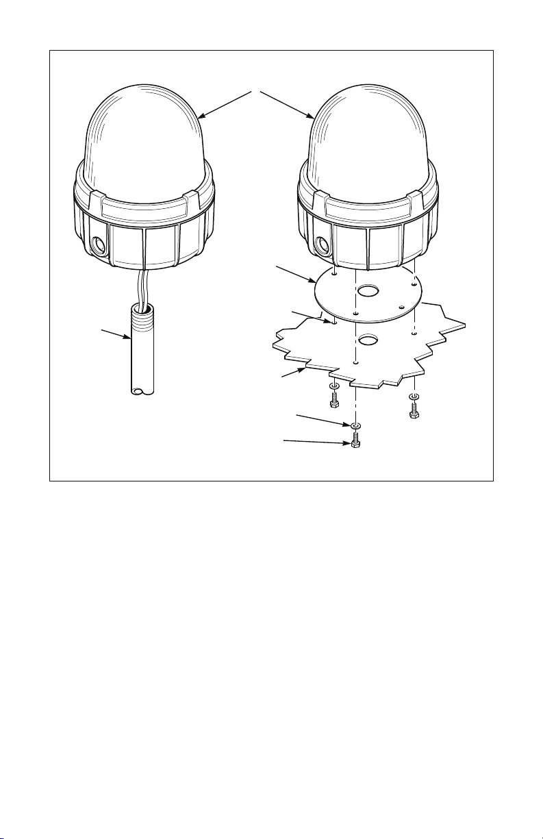
D. Electrical Connections (see Figure 2)
The Model 371DST comes assembled from the factory with three color-coded leads for wiring to a
junction box. If desired, the factory leads can be removed and the supply connections can be directly
made to the terminal block located on the backside of the mounting bracket as described below.
To avoid electrical shock hazards, do not connect to supply circuit when power is applied.
1. Disassemble the light as follows:
a. Remove dome assembly by grasping the die-cast ring attached to the dome and turning it
counter-clockwise.
b. Remove three #10 hex head screws that secure strobe-spinning assembly to housing.
c. Remove strobe-spinning assembly.
d. If desired, remove the factory field wiring leads from the terminal block.
2. If conduit side entry is to be used, attach either Myers STNTB-2 or T&B H075-TBH 3/4”
N.P.T. conduit hub with 3/4” N.P.T. close nipple (all user-supplied) to housing and tighten securely.
When using side entry, the bottom 1” NPT conduit entry must be plugged with a UL listed threaded
plug (user-supplied).
3. Route supply wires (10 AWG to 16 AWG) into the housing.
2

4. Strip a maximum of .28” (7 mm) of wire insulation from the ends of the power leads. Connect wires to
terminal block by inserting the stripped ends of the wire into the connector as far as they can travel and
tightening the clamping screw (max. tightening torque = 7.0 in-lbs {.8 N-m}).
NOTE
For DC models, polarity must be observed for proper operation. Connect the positive power supply
lead to the (+) terminal and the negative power supply lead to the (-) terminal.
5.
Connect earth ground to terminal block and green ground screw located in housing.
6. Re-assemble the light and test for proper operation.
II. MAINTENANCE.
SAFETY MESSAGE TO MAINTENANCE PERSONNEL
Listed below are some important safety instructions and precautions you should follow:
• Read and understand all instructions before operating this system.
• Any maintenance to the light system must be done with the power turned off.
•Any maintenance to the light system must be performed by a trained electrician in accordance with
NEC/CEC Guidelines and local codes.
•Never alter the unit in any manner. Safety may be endangered if additional openings or other alterations
are made to units.
•The nameplate, which contains cautionary or other information of importance to maintenance
personnel, should not be obscured.
• If the dome is damaged in any way, the complete dome assembly MUST be replaced.
• After performing any maintenance, test the light system to ensure that it is operating properly.
WARNING: EXPLOSION HAZARD—Substitution of any component may impair suitability
•
for Class I, Division 2, Groups A, B, C and D; Class II, Division 2; Class 3 or non-hazardous
locations.
• EXPLOSIONHAZARD—Donotdisconnectequipmentunlesspowerhasbeenswitchedoffor
theareaisknowntobenon-hazardous.
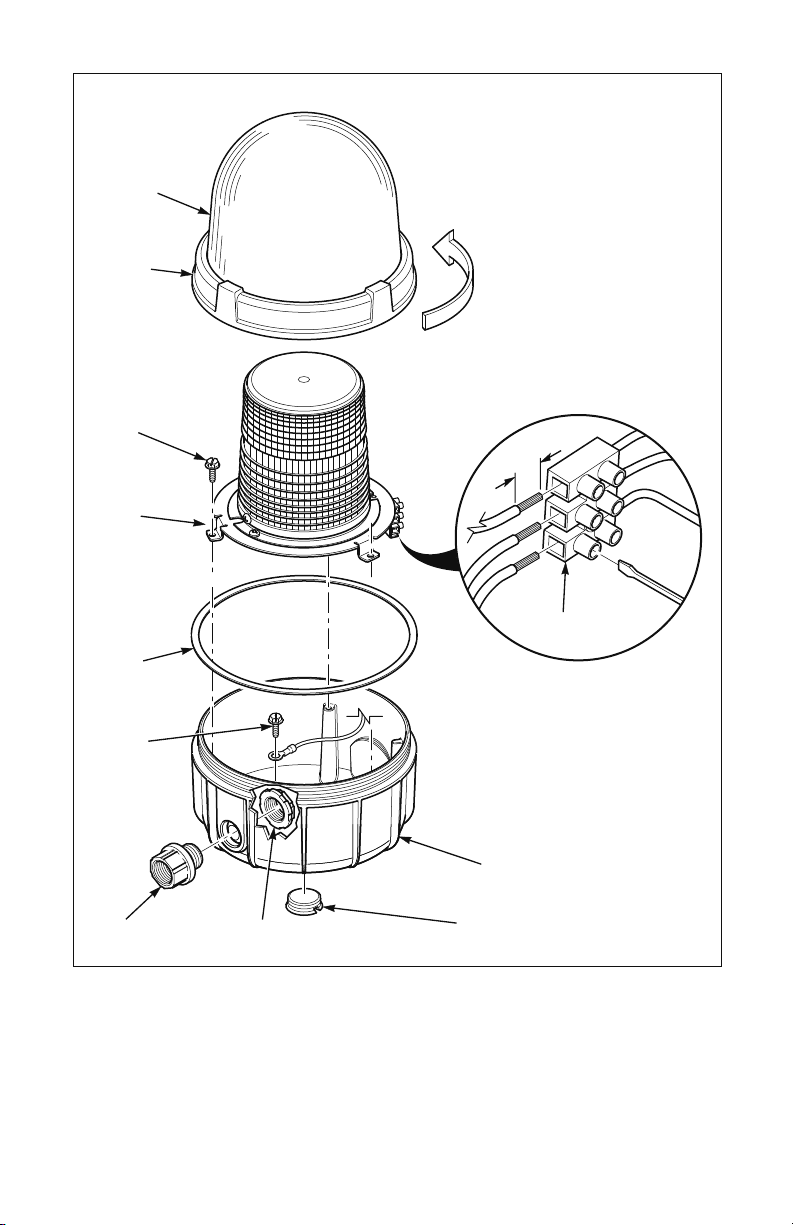
A. FLASHTUBE REPLACEMENT (see Figure 3).
After extended operation, occasionally check for flash tube degradation. Should the flash tube misfire,
have a noticeable decrease in light output, glow continuously or darken- replacement is necessary.
WARNING
HIGH VOLTAGES ARE PRESENT INSIDE THE LIGHT ASSEMBLY. WAIT AT LEAST 5 MINUTES AFTER
SHUTTING OFF POWER BEFORE SERVICING THIS UNIT.
To replace strobe tube, proceed as follows:
Remove the dome assembly by grasping the die-cast ring attached to the dome and turning it
1.
counter-clockwise. If difficulty occurs removing the dome assembly, place a screwdriver blade against
one of the four bosses on the die-cast ring attached to the dome. Gently tap the screwdriver handle
to loosen the dome assembly from the housing.
WARNING
To maintain the watertight enclosure, do not damage dome or threads while disassembling or
reassembling the unit. Lubricated threaded joints exposed for long periods of time may attract small
particles of dirt or other foreign materials. Re-assemble joint immediately after performing maintenance.
3
2. Remove the two #8 screws retaining the fresnel lens to it’s mounting base and lift the lens off the metal
spinning.
3. Carefullyremovetheashtubefromitssocketbygraspingtheconnectorandlifting
upwards using a slight rocking motion.
4. See replacement parts table (Section IIB) for a complete list of Federal Signal lamps that
areavailable.Installanewashtubebyfullyseatingitintothesocket.
5. Reassemble the unit.
6. Test light for proper operation.
B. Replacement Parts.
Description Part No.
Dome Assembly, Polycarbonate, Amber K8459125
Dome Assembly, Polycarbonate, Blue K8459125-01
Dome Assembly, Polycarbonate, Clear K8459125-02
Dome Assembly, Polycarbonate, Green K8459125-03
Dome Assembly, Polycarbonate, Red K8459125-04
Inner Lens, Polycarbonate Clear K8422B428
Dome Ring Gasket K8459123
Surface-Mount Gasket K8459127
Strobe Tube K8107178
Printed Circuit Board Assy., 12-24VDC K2001265-01
Printed Circuit Board Assy., 120VAC K200865-02
C. Optional Accessories.
Description
Part No.
Mounting Bracket, Surface 371BRCKT
Conduit hub kit, 3/4” N.P.T. K8459138
Close-up plug, 1” N.P.T. K8459130
III. SERVICE
The Federal Signal factory will service your equipment or provide technical assistance with any
problems that cannot be handled locally.
Any units returned to Federal Signal for service, inspection, or repair must be accompanied by a
Return Material Authorization. This R.M.A. can be obtained from a local Distributor or
Manufacturer’s Representative.
At this time a brief explanation of the service requested, or the nature of the malfunction, should
be provided.
Address all communications and shipments to:
Industrial Systems
2645 Federal Signal Drive • University Park, IL 60484-3167
Tel.: 1-708-534-4756 • 1-877-289-3246 • Fax: 1-708-534-4852
www.federalsignal-indust.com • www.fs-isys.com
4
1" NPT PIPE
PIPE MOUNT SURFACE MOUNT
371 LIGHT
ASSEMBLY
GASKET
DRILL (3) 9/32"
(7.143 mm) HOLES
MOUNTING
SURFACE
1/4" FLATWASHERS
1/4" SCREWS
Figure 1
5
290A3944
DOME
ASSEMBLY
DIE CAST
RING
SCREWS, #10
HEX HEAD (3)
TURN DIE CAST RING
COUNTER-CLOCKWISE
TO REMOVE
.28"
(7mm)
STROBE
SPINNING
ASSEMBLY
GASKET
GROUND
SCREW
CONDUIT HUB
(USER SUPPLIED)
CONDUIT NUT
(USER SUPPLIED)
A
Figure 2
A
TERMINAL
BASE
CONDUIT PLUG
(USER SUPPLIED)
BLOCK
290A3945
6

DOME
290A3946
ASSEMBLY
DIE CAST
RING
FRESNEL
LENS
#8 SCREWS (2)
TURN DIE CAST RING
COUNTER-CLOCKWISE
TO REMOVE
FLASH TUBE
METAL
SPINNING
BASE
Figure 3
7

Consignes d’installation et d’utilisation du Commander
®
lumières stroboscopiques, modèle 371DST -
pour une utilisation dans des endroits dangereux
Message de sécurité destiné aux installateurs,
aux utilisateurs et au personnel d’entretien
Cet appareil convient aux endroits la classe I, division 2, groupes A, B, C et D; de la classe II,
division 2; et de la classe III, ou aux endroits non dangereux seulement.
Il est important de respecter toutes les consignes jointes à ce produit au moment de l’expédition. Cet
appareil doit être installé par un électricien qualifié qui maîtrise parfaitement le Code national d’électricité /
Code d’électricité canadien et qui respectera les directives CNE/CCE ainsi que les codes locaux.
Le choix du lieu de montage du dispositif, de ses commandes et de l’acheminement des câbles doit être
effectué sous la direction de l’ingénieur responsable des installations et de l’ingénieur responsable de la
sécurité. Voici par ailleurs une liste complémentaire d’instructions et de précautions de sécurité importantes
à respecter :
• Lire et comprendre toutes les instructions avant d’installer ou d’utiliser ce matériel.
• Pour réduire le risque d’incendie dans des atmosphères dangereuses, déconnecter l’appareil du circuit
d’alimentation avant de l’ouvrir. Maintenir le dispositif fermé en cours d’utilisation.
•L’enceinte du stroboscope ne doit pas être utilisée comme chemin de câbles pour les conducteurs de
dérivation de passage.
• Après l’installation, s’assurer que le joint annulaire fileté du dôme est complètement enclenché.
• Après l’installation, tester le système lumineux pour s’assurer qu’il fonctionne correctement.
• Une fois les tests terminés, fournir une copie de cette fiche de consignesà tout le personnel de service.
•Établir une procédure de vérification régulière de l’intégrité et du bon fonctionnement de l’installation
d’éclairage.
Le non-respect de l’ensemble des mesures et consignes de sécurité peut entraîner des dommages matériels
ou entraîner des blessures graves voire mortelles pour les personnes concernées et d’autres personnes.
I. INSTALLATION
A. Déballage.
Après avoir déballé la lumière, vérifier soigneusement si elle a été endommagée lors du transport.
Si l’équipement a été endommagé, ne pas tenter de l’installer ou de le faire fonctionner. Déposer
immédiatement une réclamation auprès du transporteur, déclarant l’étendue des dommages. Examiner
soigneusement toutes les enveloppes, étiquettes d’expédition et autres étiquettes avant de les retirer ou
de les détruire.
B. Montage (voir Illustration 1).
ATTENTION
Pour réduire le risque d’incendie ou d’explosion, ne pas installer dans une zone dangereuse si la
température de fonctionnement dépasse la température d’allumage de l’atmosphère dangereuse.
Se reporter à la plaque signalétique du produit pour consulter les marquages de température de
fonctionnement.
Les lumières du modèle 371DST sont conçues pour un montage sur une surface horizontale plate
ou sur un tube à filetage conique 25,4 mm (1 po.). Pour un montage en surface sur substrats
solides, on peut utiliser un modèle 371BRCKT vendu séparément (support de montage en 3 points).
Lorsque le modèle 371BRCKT est utilisé, l’entrée de conduit de 2,54 cm (1 po.) à filetage conique
de la partie inférieure du feu doit être fermée avec un bouchon de 25,4 mm (1 po.) à filetage conique
fourni dans le kit. Si l’entrée latérale du conduit doit être utilisée, démonter la lumière comme indiqué
dans la section ID.1, puis retirer une entrée défonçable avec un instrument contondant avant de
remonter la lumière. Retirer les éclats autour de l’entrée défonçable à l’aide d’une lime.
8

1. Montage sur tube
a. Fixer la lumière sur le tube en la faisant tourner dans le sens des aiguilles d’une montre.
b. Pour obtenir des informations sur les branchements électriques, se reporter à la section D.
2. Montage en saillie
a. À l’aide du joint statique comme gabarit, faire quatre marques de repère sur la surface de montage
pour le perçage. Percer un trou de 7,1 mm (9/32 po.) de diamètre au niveau de chaque repère
extérieur pour le montage. Percer ou perforer un trou de 34,9 mm (1-3/8 po.) de diamètre au niveau
du repère central pour l’entrée destinée au fil.
b. Fixer soit un conduit de 25,4 mm (1 po.) à filetage conique, soit un concentrateur ou un connecteur
adapté de 25,4 mm (1 po.) à filetage conique fourni par l’utilisateur, pour guider l’entrée dans la partie
inférieure de la lumière.
c. Régler la lumière sur le joint statique et la fixer sur la surface de montage à l’aide des vis de 6,4 mm
(1/4 po.) et des rondelles.
d. Pour obtenir des informations sur les branchements électriques, se reporter à la section D.
C. Spécifications.
Tension de fonctionnement 12-24 VCC 120 VCA 50/60 Hz
Courant de fonctionnement 2,10 A 0,60 A
Sortie d’énergie 10,0 joules 10,0 joules
Vitesse de clignotement : 72-88 FPM 72-88 FPM
Température de fonctionnement -35 °C à 40 °C -35 °C à 40 °C
(-31 °F à 104 °F) (-31 °F à 104 °F)
Homologations UL, cUL UL, cUL
Valeurs environnementales Type 4X, IP66 Type 4X, IP66
D. Branchements électriques (voir Illustration 2)
Le modèle 371DST est assemblé à l’usine avec trois fils à code-couleur pour le raccordement à une
boîte de jonction. Au besoin, les fils de l’usine peuvent être retirés et les connexions d’alimentation
faites directement sur le bornier situé dans la partie arrière du support de montage comme décrit
ci-dessous.
Afin d’éviter les dangers de chocs électriques, ne pas brancher au circuit d’alimentation tant que le
dispositif est sous tension.
1.
Démonter la lumière comme suit :
a. Retirer le dôme en saisissant la bague en fonte fixée au dôme, puis la faire tourner dans le sens
inverse des aiguilles d’une montre.
b. Retirer les trois vis à tête hexagonale n° 10 qui maintiennent l’ensemble rotatif pour stroboscope
sur l’enceinte.
c. Retirer l’ensemble rotatif pour stroboscope.
d. Au besoin, retirer les fils de raccordement usine du bornier.
2. Si une entrée de conduit latérale est utilisée, fixer un concentrateur de conduit de 19 mm (3/4 po.)
à filetage conique de type Myers STNTB-2 ou T&B H075-TBH avec un mamelon simple de 19 mm
(3/4 po.) à filetage conique(fournis par l’utilisateur) sur l’enceinte et serrer fermement. Lorsqu’une entrée
latérale est utilisée, l’entrée de conduit de 2,54 cm (1 po.) à filetage conique de la partie inférieure doit
être fermée avec un bouchon fileté homologué UL (fourni par l’utilisateur).
9

3. Acheminer les fils d’alimentation (10 AWG à 16 AWG) dans l’enceinte.
4. Retirer un maximum de 7 mm (0,28 po.) d’isolant des extrémités des câbles d’alimentation. Brancher
les fils sur le bornier en introduisant les extrémités dénudées dans le connecteur aussi loin que possible
en serrant la vis d’arrêt (couple de serrage max. = 0,8 N-m {7,0 po.-lb.}).
REMARQUE
Sur les modèles CC, la polarité doit être respectée pour un fonctionnement approprié. Raccorder le fil
d’alimentation positif à la borne (+) et le fil d’alimentation négatif à la borne (-).
5. Raccorder la prise de terre au bornier et à la vis de terre verte située dans l’enceinte.
Remonter la lumière et vérifier son bon fonctionnement.
6.
II. ENTRETIEN.
MESSAGE DE SÉCURITÉ DESTINÉ AU PERSONNEL D’ENTRETIEN
Voici une liste d’instructions et de précautions de sécurité importantes à respecter :
• Lire et comprendre toutes les instructions avant d’utiliser ce système.
• Tout entretien du système lumineux doit être effectué lorsque l’alimentation est désactivée.
•Tout entretien du système lumineux doit être exécuté par un technicien formé conformément aux
directives du CNE/CCE ainsi qu’aux codes locaux.
•Ne jamais modifier cet appareil de quelque façon que ce soit. La sécurité peut être compromise si
d’autres ouvertures sont ajoutées ou si d’autres modifications sont apportées à ces dispositifs.
•La plaque signalétique contenant des informations de mise en garde et autres informations
importantes pour le personnel d’entretien ne doit pas être occultée.
• Si le dôme est endommagé de quelque façon que ce soit, l’intégralité du dôme DOIT être remplacée.
• Après avoir effectué l’entretien, tester le système lumineux pour s’assurer de son bon fonctionnement.
AVERTISSEMENT: RISQUE d’EXPLOSION — Remplacement de tout composant qui
•
risqueraient de qualités pour la classe I, Division 2, groupes A, B, C et D ; Classe II, Division 2 ;
Classe 3 ou emplacements non dangereux.
• RISQUEd’EXPLOSION—Nepasdebrancherlematérielsaufs’ilaétémishorstensionou
l’environnement est classé non dangereux.
A. REMPLACEMENT DE LA LAMPE-ÉCLAIR (voir Illustration 3).
Après une utilisation prolongée, vérifier ponctuellement si la lampe-éclair présente des signes de
détérioration. En cas de ratés de la lampe-éclair, de diminution apparente de l’éclairage, d’incandescence
continue ou de noircissement, la lampe-éclair doit être remplacée.
AVERTISSEMENT
L’INSTALLATION LUMINEUSE PRÉSENTE DES TENSIONS ÉLEVÉES. ATTENDEZ AU MOINS 5 MINUTES
APRÈS LA MISE HORS TENSION AVANT DE DÉBUTER UNE SÉANCE D’ENTRETIEN.
Pour remplacer le tube stroboscopique, procéder comme suit :
Retirer le dôme en saisissant la bague en fonte fixée au dôme, puis la faire tourner dans le sens
1.
inverse des aiguilles d’une montre. En cas de difficulté pour retirer le dôme, placer une lame de
tournevis contre l’un des quatre bossages de la bague en fonte fixée au dôme. Tapoter légèrement le
manche du tournevis pour dégager le dôme de l’enceinte.
AVERTISSEMENT
Pour préserver l’étanchéité de l’enceinte, ne pas endommager le dôme ou les fils lors du montage ou du
démontage du dispositif. Des joints filetés, lubrifiés, exposés pendant de longues périodes peuvent attirer
de petites particules de saleté et autres matières étrangères. Remonter le joint immédiatement après
l’opération de maintenance.
10

2. Retirer les deux vis n° 8 qui retiennent la lentille de Fresnel sur sa base de montage et ôter la lentille du
disque métallique.
3. Retirer délicatement la lampe-éclair de son réceptacle en saisissant le connecteur et en le tirant vers le
haut par un léger mouvement de bascule.
4. Se reporter au tableau des pièces de rechange (Section IIB) pour une liste complète des lampes
Federal Signal disponibles. Installer une nouvelle lampe-éclair en l’enfonçant complètement dans le
réceptacle.
5. Remonter le dispositif.
6. Tester le bon fonctionnement de la lumière.
B. Pièces de rechange.
Description N° de pièce
Dôme en polycarbonate, ambre K8459125
Dôme en polycarbonate, bleu K8459125-01
Dôme en polycarbonate, incolore K8459125-02
Dôme en polycarbonate, vert K8459125-03
Dôme en polycarbonate, rouge K8459125-04
Lentille Polycarbonate, incolore K8422B428
Joint de la bague du dôme K8459123
Joint statique, montage en saillie K8459127
Tube stroboscopique K8107178
Plaquette de circuits imprimés, 12-24 VCC K2001265-01
Plaquette de circuits imprimés, 120 VCA K200865-02
C. Accessoires.
Description N° de pièce
Support de montage, en saillie 371BRCKT
Kitconcentrateurdeconduit,19mm(3/4po.)àletageconique K8459138
Bouchondefermeture,25,4mm(1po.)àletageconique K8459130
III. ENTRETIEN
L’usine de Federal Signal procédera à l’entretien de votre équipement ou vous fournira une assistance
technique pour tout problème qui ne peut être résolu sur place.
Tous les appareils retournés à Federal Signal pour entretien, inspection ou réparation doivent être
accompagnés d’une autorisation de retour du produit. Vous pouvez obtenir cette autorisation auprès d’un
distributeur local ou d’un représentant du fabricant.
Vous devez aussi fournir une brève explication du service requis ou de la nature du dysfonctionnement lors
de la restitution de l’appareil.
Adresse pour les communications et les expéditions :
Industrial Systems
2645 Federal Signal Drive • University Park, IL 60484-3167
Tel.: 1-708-534-4756 • 1-877-289-3246 • Fax: 1-708-534-4852
www.federalsignal-indust.com • www.fs-isys.com
11

MONTAGE SUR TUBE MONTAGE EN SAILLIE
TUBE À
FILETAGE
CONIQUE
25,4MM (1 PO.)
INSTALLATION
LUMINEUSE 371
JOINT
D'ÉTANCHÉITÉ
PERCEZ TROIS TROUS
DE 7,143MM (9/32 PO.)
SURFACE DE
MONTAGE
RONDELLES PLATES
6,35MM (1/4 PO.)
VIS 6,35MM (1/4 PO.)
290A3944
Illustration 1
12

DÔME
L’UTILISATEUR)
BAGUE
EN FONTE
VIS, TÊTE
HEXAGONALE N°10 (3)
TOURNEZ LA BAGUE EN
FONTE DANS LE SENS INVERSE
DES AIGUILLES D’UNE MONTRE
POUR LA RETIRER
.28"
(7mm)
ENSEMBLE
ROTATIF POUR
STROBOSCOPE
JOINT
D’ÉTANCHÉITÉ
VIS DE
TERRE
CONCENTRATEUR
DE CONDUIT
(FOURNI PAR
ÉCROU DE
CONDUIT (FOURNI
PAR L’UTILISATEUR)
A
Illustration 2
A
BORNIER
BASE
BOUCHON DE CONDUIT
(FOURNI PAR L’UTILISATEUR)
290A3945
13

DÔME
290A3946
TOURNEZ LA BAGUE EN
FONTE DANS LE SENS INVERSE
UNE MONTRE
POUR LA RETIRER
BAGUE
EN FONTE
LENTILLE
DE FRESNEL
VIS N°8 (2)
DES AIGUILLES D’
LAMPE-ÉCLAIR
DISQUE
MÉTALLIQUE
BASE
Illustration 3
14

Instrucciones de instalación y servicio para Commander®
para el uso en ubicaciones peligrosas
Mensaje de seguridad para los instaladores,
los usuarios y el personal de mantenimiento de las luces
estroboscópicas Modelo 371DST
El uso adecuado de este equipo se limita a ubicaciones de clase I, división 2, grupos A, B, C y D;
clase II, división 2; clase III o ubicaciones no peligrosas.
Es importante seguir todas las instrucciones enviadas con este producto. Este dispositivo debe ser instalado
por un electricista capacitado completamente familiarizado con el Código Eléctrico Nacional/Código
Eléctrico de Canadá y que siga los lineamientos NEC/CEC y todos los códigos locales.
La selección de la ubicación de montaje del dispositivo, sus controles y la colocación del cableado deben
realizarse bajo la dirección del ingeniero de la planta y del ingeniero de seguridad. Asimismo, a continuación
se incluyen algunas instrucciones y precauciones importantes de seguridad que debe seguir:
• Lea y comprenda todas las instrucciones antes de instalar y poner en funcionamiento este equipo.
• Para reducir el riesgo de ignición de atmósferas peligrosas, desconecte el accesorio del circuito de
alimentación antes de abrir. Manténgalo cerrado firmemente mientras se encuentra en funcionamiento.
• La carcasa estroboscópica no se usa como conducto para conductores de circuito derivado pasante.
•Después de la instalación, asegúrese de que la unión roscada del anillo de la cúpula esté totalmente
acoplada.
• Después de la instalación, pruebe el sistema de luces para asegurar que funcione correctamente.
•Una vez que haya finalizado la prueba, entregue una copia de esta hoja de instrucciones a todo el
personal de operación.
•Establezca un procedimiento para verificar periódicamente la instalación de luz a fin de comprobar la
integridad y el funcionamiento apropiados.
Si todas estas precauciones de seguridad e instrucciones no se observan, pueden ocasionarse daños a los
bienes, lesiones graves o incluso la muerte a usted o a los demás.
I. INSTALACIÓN
A. Desembalaje.
Después de desembalar la luz, examínela para detectar daños que puedan haber ocurrido durante el
tránsito. Si el equipo ha sido dañado, no intente instalarlo ni ponerlo en funcionamiento. Presente un
reclamo de inmediato al transportista, indicando la medida de los daños. Con cuidado inspeccione
todos los sobres, las etiquetas de envío y los rótulos antes de retirarlos o destruirlos.
B. Montaje
(vealagura1).
PRECAUCIÓN
Para reducir el riesgo de incendio o explosión, no instale en una ubicación peligrosa si la temperatura
de funcionamiento excede la temperatura de ignición de atmósferas peligrosas. Consulte la placa de
identificación del producto para ver las indicaciones de temperatura de funcionamiento.
Las luces del Modelo 371DST están diseñadas para su montaje en una superficie horizontal plana
o en un tubo NPT de 1”. Para el montaje de superficie en sustratos sólidos, puede usarse el Modelo
371BRCKT (soporte para montaje de 3 puntos) que se vende por separado. Al usar el Modelo
371BRCKT, la entrada inferior de conductos NPT de 1” de la luz debe taparse con el tapón de cierre
NPT de 1” provisto con el kit. Si se usará la entrada lateral del conducto, desensamble la luz tal como
se describe en la sección ID.1 y retire el orificio precortado con una herramienta sin filo antes de
montar la luz. Use una lima para remover el exceso de rebabas alrededor del orificio precortado.
15

1. Montaje en tubo
a. Sujete la luz al tubo girando en sentido horario.
b. Consulte la sección D para obtener información sobre las conexiones eléctricas.
2. Montaje en supercie
a. Usando la junta como plantilla, trace cuatro marcas de posición de perforación en la superficie de
montaje. Perfore un orificio de 9/32" (7,1mm) de diámetro a cada lado de las marcas externas de
posición de perforación para el montaje.Taladre o perfore un orificio de 1-3/8" (34,9mm) de diámetro
en la marca central de posición de perforación para la entrada de cables.
b. Conecte un conducto NPT de 1” o un centro NPT de 1” provisto por el usuario a la entrada del
conducto en la parte inferior de la luz.
c. Coloque la luz en la junta y sujétela a la superficie de montaje con los tornillos y arandelas provistas
de 1/4".
d. Consulte la sección D para obtener información sobre las conexiones eléctricas.
C. Especificaciones.
Voltaje de funcionamiento 12-24 VCC 120 VCA 50/60 Hz
Corriente eléctrica de funcionamiento 2,10 A 0,60 A
Salida de energía 10,0 joules 10,0 joules
Velocidad de parpadeo 72-88 FPM 72-88 FPM
Temperatura de funcionamiento -31°F a 104°F -31°F a 104°F
(-35°C a 40°C) (-35°C a 40°C)
Aprobaciones UL, cUL UL, cUL
Clasificaciones ambientales Tipo 4X, IP66 Tipo 4X, IP66
D. Conexiones eléctricas (vea la figura 2)
El Modelo 371DST viene ensamblado de fábrica con cables con código de tres colores para el
cableado a una caja de conexiones. Si se desea, los cables de fábrica se pueden retirar y las
conexiones de alimentación se pueden hacer directamente en el bloque terminal ubicado en la parte
posterior del soporte de montaje como se describe a continuación.
Para evitar el riesgo de descarga eléctrica, no conecte al circuito de alimentación cuando se aplica energía.
Desensamble la luz de la siguiente manera:
1.
a. Retire la unidad de la cúpula sujetando el anillo de fundición sujeto a la cúpula y girándolo en
sentido antihorario.
b. Retire tres tornillos con cabeza hexagonal N.° 10 que sujetan la unidad de giro estroboscópico a la
carcasa.
c. Retire la unidad de giro estroboscópico.
d. Si lo desea, retire los cables de fábrica de cableado de campo desde el bloque terminal.
2. Si se debe usar la entrada lateral del conducto, conecte un centro de conductos Myers STNTB-2
o T&B H075-TBH N.P.T. de 3/4” con una. boquilla roscada de cierre N.P.T de 3/4” (todos provistos por
el usuario) a la carcasa y ajuste firmemente. Al usar la entrada lateral, la entrada inferior del conducto
NPT de 1” debe taparse con un tapón roscado homologado por UL (provisto por el usuario).
3. Tienda los cables de alimentación (10 AWG a 16 AWG) en la carcasa.
16

4. Pele un máximo de 0,28” (7 mm) de aislamiento del cable de los extremos de los cables eléctricos.
Conecte los cables al bloque terminal insertando los extremos pelados del cable en el conector lo más
lejos posible y ajustando el tornillo de sujeción (parde torsión de ajuste máx. = 7,0 in-lb {0,8 N-m}).
NOTA
Para modelos CC, debe observarse la polaridad para un funcionamiento apropiado. Conecte el cable
de alimentación positivo al terminal (+) y el cable de alimentación negativo al terminal (-).
Conecte la tierra física al bloque terminal y el tornillo verde de puesta a tierra que se ubica en la carcasa.
5.
Vuelva a ensamblar la luz y pruébela para verificar el funcionamiento correcto.
6.
II. MANTENIMIENTO.
MENSAJE DE SEGURIDAD AL PERSONAL DE MANTENIMIENTO
A continuación se incluyen algunas instrucciones y precauciones importantes de seguridad que debe seguir:
• Lea y comprenda todas las instrucciones antes de poner en funcionamiento este sistema.
• Cualquier mantenimiento del sistema de luces debe realizarse con la unidad apagada.
•Todo mantenimiento del sistema de luces debe ser realizado por un electricista capacitado de acuerdo
con los Lineamientos NEC/CEC y los códigos locales.
•No altere nunca la unidad de ninguna forma. La seguridad puede correr riesgo si se realizan aberturas
adicionales u otras alteraciones a las unidades.
•La placa de identificación, que contiene información de precaución u otra información de importancia
para el personal de mantenimiento, no debe quedar oculta.
• Si la cúpula se daña de alguna manera, DEBE reemplazarse la unidad completa de la cúpula.
•Después de realizar trabajos de mantenimiento, pruebe el sistema de luces para asegurarse de que
funcione correctamente.
• ADVERTENCIA: PELIGRO DE EXPLOSIÓN: Peligro de explosión No desconecte el equipo a
menos que el poder ha-sido apagada o el área se considere no peligrosa.
ADVERTENCIA: peligro de explosión: sustitución de cualquiera de los componentes podría
•
menoscabar la conformabilidad para clase I, División 2, grupos A, B, C y D; Clase II, División
2; Clase 3 o en lugares no peligrosos.
A. REEMPLAZO DEL TUBO DE PARPADEO
(vealagura3).
Después de un funcionamiento prolongado, ocasionalmente compruebe el tubo de parpadeo para
detectar cualquier degradación. Si el tubo de parpadeo falla al encender, presenta una reducción
significativa en la salida de luz, brilla continuamente o se oscurece, es necesario reemplazarlo.
ADVERTENCIA
HAY ALTOS VOLTAJES PRESENTES DENTRO DE LA UNIDAD DE LUZ. ESPERE AL MENOS 5 MINUTOS
DESPUÉS DE DESCONECTAR LA ALIMENTACIÓN ANTES DE REALIZAR TAREAS DE SERVICIO EN
ESTA UNIDAD.
Para reemplazar el tubo estroboscópico, proceda de la siguiente forma:
1. Retire la unidad de la cúpula sujetando el anillo de fundición sujeto a la cúpula y girándolo en sentido
antihorario. Si tiene dificultades para retirar la unidad de la cúpula, coloque una hoja de destornillador
contra una de las cuatro guías en el anillo de fundición sujeto a la cúpula. Golpee suavemente la
manija del destornillador para aflojar la unidad de la carcasa.
ADVERTENCIA
Para mantener la unidad impermeable, no dañe la cúpula ni las roscas mientras desensambla o vuelve a
ensamblar la unidad. Las uniones roscadas lubricadas expuestas por períodos prolongados pueden atraer
pequeñas partículas de polvo u otros materiales extraños. Vuelva a ensamblar la unión inmediatamente
después de realizar el mantenimiento.
17

2. Retire los dos tornillos N.° 8 que sujetan la lente fresnel en su base de montaje y levante la lente del
soporte giratorio de metal.
3. Con cuidado retire el tubo de parpadeo de su enchufe sujetando el conector y levantándolo con un
leve movimiento de balanceo.
4. Vea la tabla de piezas de repuesto (Sección IIB) para obtener una lista completa de las lámparas
de Federal Signal disponibles. Instale un nuevo tubo de parpadeo asentándolo por completo en el
enchufe.
5. Vuelva a ensamblar la unidad.
6. Pruebe el correcto funcionamiento de la luz.
B. Piezas de repuesto.
Descripción N.° de pieza
Unidad de la cúpula de policarbonato, ámbar K8459125
Unidad de la cúpula de policarbonato, azul K8459125-01
Unidad de la cúpula de policarbonato, transparente K8459125-02
Unidad de la cúpula de policarbonato, verde K8459125-03
Unidad de la cúpula de policarbonato, roja K8459125-04
Lente de policarbonato, transparente K8422B428
Junta del anillo de la cúpula K8459123
Juntademontajeensupercie K8459127
Tubo estroboscópico K8107178
Unidad del circuito impreso,12-24 VCC K2001265-01
Unidad del circuito impreso,120 VCA K200865-02
C. Accesorios.
Descripción N.° de pieza
Soportedemontaje,supercie 371BRCKT
Kit de centro de conductos, N.P.T. de 3/4” K8459138
Tapón de cierre, N.P.T. de 1” K8459130
III. SERVICIO
La fábrica de Federal realizará las tareas de servicio de sus equipos o proporcionará asistencia técnica con
los problemas que no se puedan manejar a nivel local.
Las unidades devueltas a Federal Signal para servicio, inspección o reparación deben acompañarse de una
Autorización de devolución de material. Esta autorización de devolución de material puede obtenerse de un
distribuidor local o de un representante del fabricante.
En este momento debe proporcionarse una breve explicación del servicio solicitado o la naturaleza de la
falla.
Dirija las comunicaciones y envíos a:
Industrial Systems
2645 Federal Signal Drive • University Park, IL 60484-3167
Tel.: 1-708-534-4756 • 1-877-289-3246 • Fax: 1-708-534-4852
www.federalsignal-indust.com • www.fs-isys.com
18

MONTAJE EN TUBO MONTAJE EN SUPERFICIE
TUBO
NPT DE 1"
ARANDELAS PLANAS DE 1/4"
UNIDAD
DE LUZ 371
JUNTA
PERFORAR (3)
ORIFICIOS DE
7,143 mm (9/32")
SUPERFICIE
DE MONTAJE
TORNILLOS DE 1/4"
Figura 1
290A3944
19

UNIDAD DE
LA CÚPULA
ANILLO
DE FUNDICIÓN
TORNILLOS,
N.° 10, CABEZA
HEXAGONAL (3)
GIRE EL ANILLO DE
FUNDICIÓN EN SENTIDO
ANTIHORARIO PARA RETIRAR
.28"
(7 mm)
UNIDAD
DE GIRO
ESTROBOSCÓPICO
JUNTA
TORNILLO
DE PUESTA
A TIERRA
CENTRO DE
CONDUCTOS
(PROVISTO POR
EL USUARIO)
TUERCA DE
CONDUCTOS
(PROVISTA POR
EL USUARIO)
A
Figura 2
A
BLOQUE TERMINAL
BASE
TAPÓN DE CONDUCTOS
(PROVISTO POR EL USUARIO)
290A3945
20

290A3946
GIRE EL ANILLO DE
FUNDICIÓN EN SENTIDO
ANTIHORARIO PARA RETIRAR
UNIDAD DE
LA CÚPULA
ANILLO
DE FUNDICIÓN
LENTE
FRESNEL
TORNILLOS N.° 8 (2)
TUBO DE PARPADEO
SOPORTE GIRATORIO
DE METAL
BASE
Figura 3
21

Industrial Systems
2645 Federal Signal Drive
University Park, IL 60484-3167
Phone: 1-877-289-3246 • 1-708-534-4756 • Fax: 1-708-534-4887
www.federalsignal-indust.com • www.fs-isys.com
© 2013 Federal Signal Corp.
 Loading...