


MODELS 350 and 450
INSTALLATION INSTRUCTIONS FOR AC AND DC VIBRATORY HORNS
MODELOS 350 y 450
INSTRUCCIONES DE INSTALACION PARA CORNETAS VIBRATORIAS DE
CA Y CC
MODELES 350 and 450
INSTRUCTIONS D’INSTALLATION POUR KLAXON VIBRATOIRE EN
COURANT ALTERNATIF ET COURANT CONTINU
INSTALLATION INSTRUCTIONS FOR AC AND DC VIBRATORY HORNS
SAFETY MESSAGE TO INSTALLERS
People’s lives depend on your safe installation of our products. It is important to follow all instructions
shipped with the products. This device is to be installed by a trained electrician who is thoroughly familiar
with the National Electrical Code and will follow the NEC Guidelines as well as local codes.
The selection of the mounting location for the device, its controls and the routing of the wiring is to be
accomplished under the direction of the Facilities Engineer and the Safety Engineer. In addition, listed
below are some other important safety instructions and precautions you should follow:
• Read and understand all instructions before installing or operating this equipment.
• Do not connect this unit to the system when power is on.
• Optimum sound distribution will be severely reduced if any objects are in front of the horn. You should
ensure that the front of the horn is clear of any obstructions.
• All effective warning horns produce loud sounds which may cause, in certain situations, permanent
hearing loss. The device should be installed far enough away from potential listeners to limit their
exposure while still maintaining its effectiveness. The OSHA Code of Federal Regulations 1910.95
Noise Standard provides guidelines which may be used regarding permissible noise exposure levels.
• After installation, ensure that all mounting screws are tightened.
• Establish a procedure to routinely check the signal system for proper activation and operation.
• Provide a copy of these instructions to the Safety Engineer, operator(s) and maintenance personnel.
• File these instructions in a safe place and refer to them when maintaining and/or reinstalling the device.
Failure to follow all safety precautions and instructions may result in property damage, serious injury, or
death to you or others.
SAFETY MESSAGE TO MAINTENANCE PERSONNEL
• Read and understand all instructions before performing any maintenance to this unit.
• To reduce the risk of electrical shock or ignition of hazardous atmospheres, do not perform maintenance/
service on this device when circuits are energized.
• Optimum sound distribution will be reduced if the front of the horn becomes clogged with a foreign
substance. Periodic checks should be performed to ensure foreign substances are not packed into the
front of the horn.
• Any maintenance to the unit MUST be performed by a trained electrician in accordance with NEC
Guidelines and local codes.
• Never alter the unit in any manner.
• The nameplate, which may contain cautionary or other information of importance to maintenance
personnel, should not be obscured if exterior of housing is painted.
Failure to follow all safety precautions and instructions may result in property damage, serious injury, or
death to you or others.
A. Introduction.
Both the AC and the DC Models are installed in identical housings. As a result, all of the installation
instructions in this sheet apply equally to both models.
In all installations, it is recommended that the electrical wiring to the installation site be completed
before the horn is mounted. Installations are subject to local electrical and fire codes.
B. Audibility and Electrical Ratings.
Voltage Current (Amps) Hz dB* dB**
120 0.18/0.22 50/60 100 94
230-240 0.09 50/60 100 94
* Measured on-axis at ten feet/3Meters in an anechoic chamber.
** Underwriters Laboratories ominidirectional sound pressure level rating at ten feet.
C. Basic Installation.
The basic horn installation consists of mounting the horn on an existing 4" x 4" outlet box.
Do not connect wires when power is on.
Connect the horn electrical leads to the power source with user-supplied wire nuts.
-1-
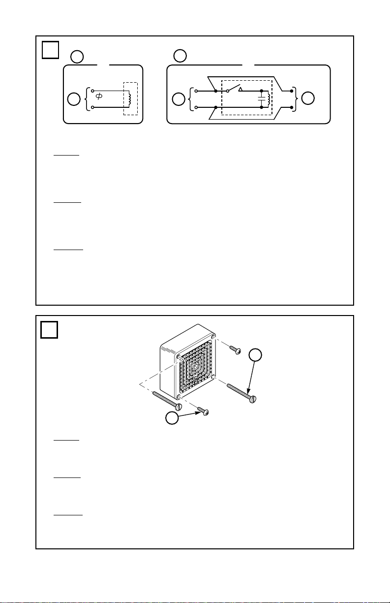
To minimize entry of foreign materials and moisture into the housing, ALWAYS install the two
10-32 x 1/2" Phillips head Taptite screws in the holes opposite the mounting screws.
NOTE
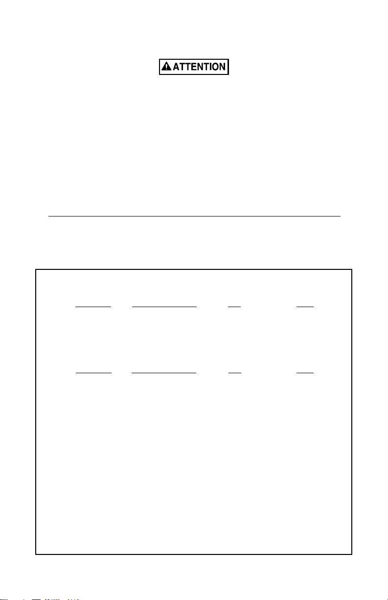
The Model 450 contains two red and two black wires. One set of wires (one black and one red) is used for
the incoming power. The other set should be used for the outgoing power. If the outgoing wiring is not
required, the remaining set of wires should be properly terminated. (Diagram A).
Mount the horn on the outlet box using the 8-32 x 1-5/8" screws provided, as indicated in the figure.
(Diagram B).
1. Surface Mounting.
Refer to the introduction, warning message to installers, and basic installation instructions
above before installing horn.
To mount the horn on a wall or other flat vertical surface, mount a Model NB Knockout Box with
four #10 x 1" wood screws (not supplied). Connect the horn’s electrical leads to the power source
with user-supplied wire nuts. Mount the horn on the NB Knockout Box with the two 8-32 x 1-5/8"
screws provided. (Diagram C).
2. Semi-flush Mounting.
Refer to the introduction, warning message to installers, and basic installation instructions
above before installing horn.
A vibratory horn can be semi-flush mounted to a wall with a 4" x 4" electrical junction box when a
Model SF Wall Plate is used. If semi-flush mounting is used, a plaster ring (raised cover) may be
required. A plaster ring is not provided because the depth requirements usually vary from
installation to installation.
Connect the horn’s electrical leads to the power source with user-supplied wire nuts.
Use the four 6-32 x 1/4" slotted head screws to attach the SF Wall Plate to the plaster ring. Use the
8-32 x 1-5/8" screws included with the horn to mount the horn on the plate. (Diagram D).
3. Weatherproof Mounting.
Refer to the introduction, warning message to installers, and basic installation instructions above before
installing horn.
Weatherproof mounting of a vibratory horn requires the use of a Model WB Weatherproof Box,
when a NEMA Type 4X rating is required. The WB is gasketed and has two (2) 3/4" and one (1) 1/
2" tapped openings to accomodate 3/4" and 1/2" conduit. When mounting the horn on the WB, use
the 8-32 x 1-5/8" screws included with the horn. (Diagram E).
4. Flush Mounting.
Refer to the introduction, warning message to installers, and basic installation instructions above before
installing horn.
In order to flush mount the horn, a Model FB Wall Box must be installed in the wall. Use four #10
x 1" screws for mounting the box. Before installing the horn in the box, use the two 10-32 x 1/2"
Phillips head screws to attach the Model FG Grille to the horn. Connect the electrical wiring to the
horn with user-supplied wire nuts and install the horn and grille assembly in the wall box using the
two 8-32 x 2" slotted head screws provided. When installing the horn in the Model FBL Wall Box,
use the 8-32 x 3" oval head screws included with the FG Grille. (Diagram F).
-2-
5. Concealed Conduit Mounting.
Refer to the introduction, warning message to installers, and basic installation instructions
above before installing horn.
The concealed conduit mounting method may be useful when an existing junction box will not
accommodate the basic installation. This installation configuration requires the use of a Model NB
Knockout Box and a Model CC Adapter Plate. Use the pair of 6-32 or 8-32 flat head screws to
mount the plate on the existing box. Install the insulated bushing in the rear of the knockout box
before attaching the box to the adapter plate with two 10-32 x 1/4" round head screws. The
insulated bushing protects the power leads that pass through the center hole in the CC Adapter
Plate and the center knockout of the WB box to the horn. (Diagram G).
6. PR Projector Installation.
Refer to the introduction, warning message to installers, and basic installation instructions above before
installing horn.
The Model PR Projector can be added to any of the installations described on this sheet. Secure
the projector to the horn with the two 10-32 x 1/2" Phillips head Taptite screws provided in the
accessory kit. Use two additional 8-32 slotted head screws (provided) in the remaining mounting
holes of the projector. If it is desired to use either of the projectors when the horn is flush
mounted, it is necessary to install the Model SF Plate instead of the FG Grille. (Diagram H).
7. PR2 Projector Installation.
Refer to the introduction, warning message to installers, and basic installation instructions above before
installing horn.
The Model PR2 Projector can be added to any of the installations described on this sheet. Secure
the projector to the horn with the two 10-32 x 1/2" Phillips head Taptite screws provided in the
accessory kit. Use two additional 8-32 slotted head screws (provided) in the remaining mounting
holes of the projector. If it is desired to use either of the projectors when the horn is flush
mounted, it is necessary to install the Model SF Plate instead of the FG Grille. (Diagram I).
8. Weatherproof Panel Mounting.
Refer to the introduction, warning message to installers, and basic installation instructions above before
installing horn.
The Model TR trim ring can be installed with the horn for panel mounting applications requiring
Type 4X Rating. Center the trim ring between the panel and the horn. Secure the assembly to the
panel using the (4) 8-32 x 1-5/8" screws, screw collars, and keps nuts (Diagram J).
NOTE
Only the hardware supplied with the Model TR should be used to ensure the Type 4X Rating.
9. Optional Weatherproof Panel Mounting Kit.
When mounting the horn in a panel application requiring a NEMA 4X Rating, purchase Kit No.
8435666. This weatherproof mounting kit includes a gasket and hardware for flush mounting
(Diagram K) the horn.
-3-
INSTRUCCIONES DE INSTALACION PARA CORNETAS VIBRATORIAS DE CA Y CC
MENSAJE DE SEGURIDAD PARA LOS INSTALADORES
La vida de personas depende de la instalación segura de nuestros productos. Es importante seguir las
instrucciones enviadas con los productos. Este dispositivo debe ser instalado por un electricista calificado
que esté bien familiarizado con el NEC y siga sus guías así como los códigos locales.
La selección del sitio de montaje del dispositivo, sus controles y la ruta de alambrado, se hará bajo la
dirección del Ingeniero de las facilidades y el Ingeniero de Seguridad. Además, a continuación se listan
otras instrucciones y precauciones de seguridad importantes que se deben seguir:
• Lea y entienda todas las instrucciones antes de instalar o de hacer funcionar este equipo.
• No conecte esta unidad al sistema con la corriente de energía encendida.
• La distribución óptima del sonido se verá muy disminuida si se encuentra algún objeto delante de la
sirena. Debe asegurarse de que el frente de la sirena esté libre de cualquier obstrucción.
• Todas las sirenas de advertencia eficaces producen sonidos fuertes que pueden causar, en ciertas
situaciones, pérdida permanente de la audición. Este dispositivo se debe instalar suficientemente alejado
de cualquier escucha potencial para limitar su exposición mientras continúa manteniendo su eficacia. El
Código OSHA de regulaciones federales, Norma sobre ruidos 1910.95 ofrece una guía que se puede
utilizar para informarse sobre los niveles de exposición al ruido que son permisibles.
• Después de la instalación, asegúrese de que todos los tornillos de montaje estén ajustados.
• Establezca un procedimiento de rutina para revisar el sistema de señal y verificar una activación y
funcionamiento adecuados.
• Proporcione una copia de estas instrucciones al Ingeniero de seguridad, a los operadores y al personal de
mantenimiento.
• Archive estas instrucciones en un lugar seguro y consúltelas cuando efectúe el mantenimiento y/o la
reinstalación del dispositivo.
El no seguir todas la instrucciones y precauciones de seguridad, puede provocar daños a la propiedad,
lesiones severas y aún su muerte o la de otros.
MENSAJE DE SEGURIDAD AL PERSONAL DE MANTENIMIENTO
• Lea y entienda todas las instrucciones antes de efectuar ningún tipo de mantenimiento a esta unidad.
• Para reducir el riesgo de choque eléctrico o ignición de atmósferas peligrosas, no efectúe el
mantenimiento/servicio de este dispositivo cuando los circuitos tienen corriente.
• La distribución óptima del sonido se verá reducida si el frente de la sirena está obstruido con una
sustancia extraña. Se deben realizar verificaciones periódicamente para asegurarse de que no hay
ninguna sustancia extraña acumulada en el frente de la sirena.
• Cualquier tipo de mantenimiento a la unidad DEBE ser realizado por un electricista capacitado y de
acuerdo con las Pautas NEC y los códigos locales.
• Nunca altere la unidad en forma alguna.
• La placa de identificación, que puede contener información de precaución u otra información importante
para el personal de mantenimiento, no debe quedar cubierta si se pinta el exterior del dispositivo.
El no seguir todas la instrucciones y precauciones de seguridad, puede provocar daños a la propiedad,
lesiones severas y aún su muerte o la de otros.
A. Introduccion.
Ambos modelos el de CA y el de CC, se instalan en cajas idénticas. Como consecuencia, todas las
instrucciones de instalación en esta hoja, aplican igualmente a ambos modelos.
En todas las instalaciones, se recomienda que el cableado eléctrico al sitio de instalación, se complete
antes de montar la corneta. La instalación está sujeta a los códigos eléctricos locales y los de
incendio.
-4-

B. Clasificaciones eléctricas y de audibilidad.
VOLTAJE CORRIENTE (AMPS) Hz dB* dB**
120 0.18/0.22 50/60 100 94
230-240 0.09 50/60 100 94
* MEDICIÓN EN AXIS A 10 PIES/ 9 METROS EN UNA CÁMARA ANECOICA.
** VALOR DEL NIVEL DE PRESIÓN DE SONIDO OMNIDIRECCIONAL A 10 PIES EN LOS
LABORATORIOS DEL ASEGURADOR
C. Instalacion Basica.
La instalación básica de la corneta consiste en montarla en una caja 4" X 4" existente.
No conecte cables con corriente.
Conecte los conductores de electricidad de la sirena a la fuente de energía con tuercas para hilos
proporcionadas por el usuario.
Para minimizar la entrada de materiales extraños y humedad dentro de la caja, SIEMPRE instale los dos
tornillos Taptite cabeza Philips en los huecos opuestos a los tornillos de montaje.
NOTA
El Modelo 450 contiene dos cables rojos y dos cables negros. Un juego de cables (uno negro y uno rojo)
se usan para la corriente entrante. El otro juego se debe usar para la corriente saliente. Si no se requiere
un cableado de salida, se debe terminar adecuadamente el otro juego de cables (diagrama A).
Monte la corneta sobre la caja de salida usando los tornillos de máquina 8-32 x 1-5/8" sumistrados,
de cabezaranurada, como se indica en la figura. (Diagrama B).
1. El Montar en Superficie.
Lea la introducción, el mensaje de advertencia a los instaladores y las instrucciones básicas de instalación
antes de instalar la corneta.
Para montar la corneta en una pared u otra superficie plana vertical, monte una caja de discos
removibles modelo NB con cuatro tornillos de madera #10 x 1" (no suministrados). Conecte las
terminales eléctricas de la corneta a la fuente de potencia con los capuchones para cable
suministrados por el usuario. Monte la corneta en la caja NB con los dos tornillos maquinados 832 x 1-5/8" de cabeza ranurada provistos. (Diagrama C).
2. Montaje Semi-empotrado.
Lea la introducción, el mensaje de advertencia a los instaladores y las instrucciones básicas de instalación
antes de instalar la corneta.
Una corneta vibratoria puede ser montada semi-empotrada a una pared con una caja eléctrica de
unión de 4" x 4" cuando se usa un plato de pared modelo SF. Si se usa un montaje semiempotrado, se puede requerir un anillo de relleno (tapa levantada). No se provee dicho anillo,
porque la profundidad requerida usualmente varia de instalación a instalación.
Conecte las terminales eléctricas de la corneta a la fuente de alimentación con los capuchones para
cable suministrados por el usuario.
Use los cuatro tornillos de cabeza ranurada de 6-32 x 1/4" para unir el Plato de pared modelo SF al
anillo de relleno. Use los tornilllos de 8-32 x 1-5/8" incluídos con la corneta para montarla en el
plato. (Diagrama D).
-5-

3. Montaje a Prueba de Intemperie.
Lea la introducción, el mensaje de advertencia a los instaladores y las instrucciones básicas de instalación
antes de instalar la corneta.
El montaje a prueba de intemperie de una corneta vibratoria requiere el uso de una caja a prueba de
la intemperie modelo WB. La WB está empaquetada y roscada para recibir conducto de 3/4" o 1/
2". Cuando monte la corneta en la WB, use los tornillos maquinados de cabeza ranurada de 8-32 x
1-5/8" incluídos con la corneta. (Diagrama E).
4. Montaje Empotrado.
Lea la introducción, el mensaje de advertencia a los instaladores y las instrucciones básicas de instalación
antes de instalar la corneta.
Con el fin de montar la corneta a nivel, se debe instalar en la pared una caja de pared Modelo FB.
Use cuatro tornillos #10 x 1" para montar la caja. Antes de intalar la corneta en la caja, use los dos
tornillos de cabeza Phillips de 10-32 x 1/2" para unir la reja Modelo FG a la corneta. Conecte el
cableado eléctrico a la corneta con los capuchones para cable suministradas por el usuario e instale
el conjunto de corneta y reja en la caja de pared usando los dos tornillos de cabeza ranurada 8-32 x
2" sumistrados. Cuando instale la corneta en la caja de pared Modelo FBL, use los tornillos de
cabeza ovalada 8-32 x 3" incluidos con la reja FG. (Diagrama F).
5. Montaje de Conduit Embebido.
Lea la introducción, el mensaje de advertencia a los instaladores y las instrucciones básicas de instalación
antes de instalar la corneta.
El método de montaje de conduit embebido puede ser útil cuando una caja de conexión existente
no se acomoda a la instalación básica. Esta configuración de instalación requiere el uso de una caja
de discos removibles Modelo NB y un plato adaptador Modelo CC. Use el par de tornillos de
cabeza plana de 6-32 u 8-32 para montar el plato a la caja existente. Instale el buje aislado en la
parte trasera de la caja antes de unir la caja al plato adaptador con dos tornillos de cabeza redonda
de 10-32 x 1/4". El buje aislado proteje las terminales de potencia que pasan a través del hueco
central en el plato adaptador CC y en el hueco central de la caja WB a la corneta. (Diagrama G).
6. Instalacion del Proyector PR.
Lea la introducción, el mensaje de advertencia a los instaladores y las instrucciones básicas de instalación
antes de instalar la corneta.
El proyector modelo PR se puede adicionar a cualquiera de las instalaciones descritas en esta hoja.
Asegure el proyector a la corneta con los dos tornillos Taptite de cabeza en cruz 10-32 x 1/2"
sumistrados en el juego de accesorios. Use los dos tornillos adicionales de cabeza ranurada de 8-32
(sumistrados) en los huecos de montaje remanentes del proyector. Si se desea usar alguno de los
proyectores cuando la corneta se monta a ras, hay que instalar el plato modelo SF en lugar de la
reja FG. (Diagrama H).
-6-

7. Instalacion del Proyector PR2.
Lea la introducción, el mensaje de advertencia a los instaladores y las instrucciones básicas de instalación
antes de instalar la corneta.
El proyector modelo PR2 se puede agregar a cualquiera de las instalaciones descritas en esta hoja.
Asegure el proyector a la corneta con los dos tornillos Taptite de cabeza en cruz de 10-32 X 1/2"
provistos en el juego de accesorios. Use los dos tornillos de cabeza ranurada de 8-32 adicionales
(sunistrados) en los huecos de montaje remanentes del proyector. Si se desea usar cualquiera de los
proyectores cuando la corneta se monta a ras, es necesario instalar el plato modelo SF en lugar de
la reja FG. (Diagrama I).
8. Montaje de panel a prueba de intemperie.
Consulte la introducción, el mensaje de advertencia a los instaladores y las instrucciones de instalación
básica precedentes antes de instalar la bocina.
El anillo de acabado del modelo TR puede instalarse con la bocina para aplicaciones de montaje
de panel que requieran clasificación NEMA 4X. Centre el anillo de acabado entre el panel y la
bocina. Asegure el conjunto al panel usando los 4 tornillos 8-32 x 1-5/8", las abrazaderas y las
tuercas Keps (Diagrama J).
NOTA
Sólo deben usarse los accesorios suministrados con el modelo TR para garantizar la clasificación
4X.
9. Juego opcional para montaje de panel a prueba de intemperie.
Al montar la bocina en una aplicación de panel que requiera clasificación NEMA 4X, compre el
juego No. 8435666. Este juego de montaje a prueba de intemperie incluye una junta de
empaquetadura y accesorios para el montaje empotrado (Diagrama K) de la bocina.
-7-

INSTRUCTIONS D’INSTALLATION POUR KLAXON VIBRATOIRE EN COURANT
ALTERNATIF ET COURANT CONTINU
MESSAGE DE SECURITE AUX INSTALLATEURS
Des vies humaines dépendent de votre installation de nos produits en sécurité. Il est important de lire,
comprendre et suivre toutes les instructions expédiées avec ce produit. Ce dispositif doit être installé par
des électriciens professionnels qui sont complètement au courant du Code Electrique National et
respecteront les recommandations NEC ainsi que les codes locaux.
Le choix de l’endroit de montage du dispositif, de ses commandes et du passage des câbles doit être
effectué sous la direction de l’ingénieur des services électriques et de l’ingénieur de sécurité. De plus, sont
énumérées ci-dessous quelques autres instructions et précautions de sécurité importantes que vous devez
suivre:
• Lisez et comprenez bien toutes les instructions avant d’installer ou de faire fonctionner cet équipement.
• Ne branchez pas cet appareil au système lorsqu’il est sous tension.
• La répartition sonore optimale sera grandement réduite s’il y a des objets devant l’avertisseur. Vous
devez vous assurer qu’il n’y a aucune obstruction devant l’avertisseur.
• Tous les avertisseurs efficaces produisent des sons forts qui pourraient causer, dans certaines situations,
des pertes auditives permanentes. Le dispositif doit être installé assez loin des auditeurs possibles pour
limiter leur exposition tout en conservant l’efficacité du dispositif. Les normes de bruit nationales, telles
que le OSHA Code of Federal Regulations 1910.95 aux États-Unis, offrent des directives que vous
pouvez utiliser en matière de niveaux d’exposition au bruit acceptables.
• Après l’installation, assurez-vous que toutes les vis de montage ont été bien resserrées.
• Établissez une procédure de vérification de routine de l’installation de signalisation pour s’assurer de son
activation et de son bon fonctionnement.
• Fournissez une copie de ces instructions à l’ingénieur responsable de la sécurité, aux opérateurs et au
personnel responsable de l’entretien.
• Rangez ces instructions dans un endroit sûr et reportez-vous-y au moment de l’entretien et/ou de la
réinstallation de l’appareil.
Si on ne respecte pas ces précautions de sécurité, il peut en résulter des dommages aux biens, des blessures
graves ou mortelles pour vous ou d’autres.
• Lisez et comprenez bien toutes les instructions avant d’effectuer tout travail d’entretien ou réparation sur
MESSAGE DE SECURITE AU PERSONNEL D’ENTRETIEN
cet appareil.
• Pour réduire les risques de chocs électriques ou d’inflammation d’atmosphères dangereuses, n’effectuez
pas d’entretien ni de réparation à l’appareil lorsque les circuits sont sous tension.
• La répartition sonore optimale sera réduite s’il y a des substances étrangères bloquant l’avertisseur. Il
faut prévoir des vérifications périodiques pour s’assurer qu’il n’y a pas de substances étrangères à
l’avant de l’avertisseur.
• L’entretien et la réparation de l’appareil DOIVENT être effectués par un électricien formé
conformément aux codes locaux et aux directives du NEC.
• Ne modifiez jamais l’appareil de quelque façon que ce soit.
• La plaque signalétique pouvant contenir des informations de mise en garde et autres informations
importantes pour le personnel responsable de l’entretien ne doit pas être obscurcie si l’on peint
l’extérieur de la demeure.
Si on ne respecte pas ces précautions de sécurité, il peut en résulter des dommages aux biens, des blessures
graves ou mortelles pour vous ou d’autres.
A. Introduction.
Les modèles en courant alternatif et courant continu sont tous deux installés dans des carters
identiques. Il en résulte que toutes les instructions d’installation de cette fiche s’appliquent également
aux deux modèles.
Dans toutes les installations, il est recommandé que le câblage électrique jusqu’au site d’installation
soit exécuté avant le montage du klaxon. Les installations sont soumises aux codes électriques locaux
et d’incendie.
-8-
B. Audibilité et régime nominal électrique.
TENSION COURANT (A) Hz dB* dB**
120 0.18/0.22 50/60 100 94
230-240 0.09 50/60 100 94
* MESURÉ DANS L’AXE À 3 MÈTRES DANS UN CHAMBRE SOURDE.
** LABORATOIRE DE CONTRÔLE PRESSION SONORE OMNIDIRECTIONNELLE
NOMINALE À 3 MÈTRES.
C. Installation de Base.
L’installation de base du klaxon consiste en montage du klaxon sur un boîtier de sortie existant 4" x
4".
Ne connectez pas les fils si la tension n’est pas coupée.
Raccordez les fils électriques de l’avertisseur à la source de courant avec des écrous de fils fournis par
l’utilisateur.
Pour minimiser l’entrée de matières étrangères et d’humidité dans le carter, installez TOUJOURS les deux
vis Taptite à tête cruciforme 10-32 x 1/2" dans les trous en face des vis de montage.
NOTE
Le modèle 450 contient deux fils rouges et deux fils noirs. Un jeu de fils (un noir et un rouge) sert pour
l’entrée du courant. L’autre jeu sert pour la sortie du courant Si les fils de sortie ne sont pas requis, il faut
fermer correctement le jeu de fils (Diagramme A).
Montez le klaxon sur le boàtier de sortie à l’aide des vis usinées à tête fendue 8-32 x 1-5/8"
fournies, comme indiqué sur la figure ci-dessous. (Diagramme B).
1. Montage en Surface.
Référez-vous à l’introduction, message d’avertissement aux installateurs et aux instructions
d’installation de base ci-dessus avant d’installer le klaxon.
Pour monter le klaxon sur un mur ou autre surface verticale plane, montez un boïtier Knockout
Modèle NB avec quatre vis à bois 10 x 1" (non fournies). Connectez les câbles électriques du
klaxon à la source d’alimentation avec des écrous de fils (fourniture utilisateur). Montez le klaxon
sur le boïtier Knockout NB avec les deux vis usinées à tête fendue 8-32 x 1-5/8" fournies.
(Diagramme C).
2. Montage Semi-encastre.
Référez-vous à l’introduction, au message d’avertissement aux installateurs, et aux instructions
d’installation de base avant d’installer le klaxon.
Un klaxon vibratoire peut être monté semi-encastré sur un mur avec un boîtier de jonction
électrique 4" x 4" lorsqu’une plaque murale Modèle SF est utilisée. Si un montage semi-encastré
est utilisé, un anneau-plâtre (couvercle en saillie) peut être nécessaire.
Un anneau-plâtre n’est pas prévu parce que les exigences en profondeur varient généralement
d’installation à installation.
Connectez les câbles électriques du klaxon à la source d’alimentation avec les écrous de fils
fournis par l’utilisateur.
Utilisez les quatre vis à tête fendue 6-32 x 1/4" pour fixer la plaque murale SF à l’anneau-plâtre.
Utilisez les vis 8-32 x 1-5/8" incluses avec le klaxon pour monter le klaxon sur la plaque.
(Diagramme D).
-9-

3. Montage Anti-intemperies.
Référez-vous à l’introduction, au message d’avertissement aux installateurs, et aux instructions
d’installation de base avant d’installer le klaxon.
Le montage anti-intempéries d’un klaxon vibratoire nécessite l’utilisation d’un boîtier antiintempéries Modèle WB. Le WB a un joint et il est taraudé pour recevoir un conduit de 1/2.” Lors du
montage du klaxon sur le WB, utilisez les vis usinées à tête fendue 8-32 x 1-5/8" incluses avec le
klaxon. (Diagramme E).
4. Montage Encastre.
Référez-vous à l’introduction, au message d’avertissement aux installateurs, et aux instructions
d’installation de base avant d’installer le klaxon.
Pour monter le klaxon encastré, un boîtier mural Modèle FB doit être installé dans le mur. Utilisez
quatre vis 10 x 1" pour monter le boîtier. Avant d’installer le klaxon dans le boîtier, utilisez les
deux vis à tête cruciforme 10-32 x 1/2" pour fixer la grille du Modèle FG au klaxon. Connectez le
câblage électrique au klaxon avec les écrous de fils fournis par l’utilisateur et installez le klaxon et
la grille ensemble dans le boîtier mural à l’aide des vis à tête fendue 8-32 x 2" fournies. Lors de
l’installation du klaxon dans le boîtier mural Modèle FBL, utilisez les vis à tête ovale 8-32 x 3"
incluses avec la grille FG. (Diagramme F).
5. Montage sur Conduit Cache.
Référez-vous à l’introduction, message d’avertissement aux installateurs, et aux instructions
d’installation de base ci-dessus avant d’installer le klaxon.
La méthode de montage sur conduit caché peut être utile lorsqu’un boîtier de jonction existant ne
peut recevoir l’installation de base. Cette configuration nécessite l’utilisation d’un boîtier
Knockout Modèle NB et une plaque adaptateur Modèle CC. Utilisez la paire de vis à tête plate 632 ou 8-32 pour monter la plaque sur le boîtier existant. Installez la bague isolée dans l’arrière du
boîtier Knockout avant d’attacher le boîtier à la plaque adaptateur avec deux vis à tête ronde 10-32
x 1/4". La bague isolée protège les câbles d’alimentation qui passent à travers le trou central dans
la plaque adaptateur CC et le centre jetable du boîtier WB vers le klaxon. (Diagramme G).
6. Installation de Cornet PR.
Référez-vous à l’introduction, message d’avertissement au x installateurs, et aux instructions
d’installation de base ci-dessus avant d’installer le klaxon.
Le cornet Modèle PR peut être ajouté à toute installation décrite sur cette fiche. Fixez le cornet au
klaxon avec les deux vis Taptite à tête cruciforme 10-32 x 1/2" fournies dans le kit d’accessoires.
Utilisez deux vis à tête fendue supplémentaires 8-32 (fournies) dans les trous de montage restant
du cornet. S’il est désiré d’utiliser un des cornets lorsque le klaxon est monté encastré, il est
nécessaire d’installer la plaque Modèle SF au lieu de la grille FG. (Diagramme H).
7. Installation du Cornet PR2.
Référez-vous à l’introduction, message d’avertissement aux installateurs, et aux instructions
d’installation de base ci-dessus avant d’installer le klaxon.
Le cornet Modèle PR2 peut être ajouté à toute installation décrite sur cette fiche. Fixez le cornet
au klaxon avec les deux vis Taptite à tête cruciforme 10-32 x 1/2" fournies dans le kit
d’accessoires. Utilisez deux vis à tête fendue supplémentaires 8-32 (fournies) dans les trous de
montage restants du cornet. S’il est désiré d’utiliser un des cornets lorsque le klaxon est monté
encastré, il est nécessaire d’installer la plaque Modèle SF au lieu de la grille FG. (Diagramme I).
-10-
8. Montage de panneau résistant aux intempéries.
Se référer à l’introduction, au message d’avertissement aux installateurs, et aux instructions d’installation
L’anneau enjoliveur Modèle TR peut être installé avec l’avertisseur pour les applications de
montage de panneau nécessitant la valeur nominale Type 4X. Centrer l’anneau enjoliveur entre le
panneau et l’avertisseur. Fixer l’assemblage au panneau en utilisant les (4) vis 8-32 x 1-5/8", les
colliers filetés, et les écrous d’arrêt (Diagramme J).
Seul le matériel fourni avec le Modèle TR doit être utilisé pour assurer la valeur nominale Type
4X.
9. Kit de montage de panneau résistant aux intempéries en option.
Lors du montage de l’avertisseur dans une application de panneau nécessitant une valeur nominale
NEMA 4X, achetez le Kit No. 8435666. Ce kit de montage résistant aux intempéries inclut un
joint et du matériel pour l’encastrement (Diagramme K) de l’avertisseur.
basiques avant d’installer l’avertisseur.
REMARQUE
AUDIBILITY INFORMATION
AC HORNS
VOLTAGE CURRENT (AMPS) dB* dB**
12 0.9 94 91
24 0.9 100 94
120 0.18 100 94
240 0.09 100 94
DC HORNS
VOLTAGE CURRENT (AMPS) dB* dB**
12 0.50 99 94
24 0.25 99 94
125 0.05 99 94
250 0.025 99 94
* MEASURED ON-AXIS AT TEN FEET/3 METERS IN AN ANECHOIC CHAMBER.
** UNDERWRITERS LABRATORIES OMNIDIRECTIONAL SOUND PRESSURE LEVEL
RATING AT TEN FEET.
* MEDICION EN AXIS A 10 PIES/9 METROS EN UNA CAMARA ANECOICA.
** VALOR DEL NIVEL DE PRESION DE SONIDO OMNIDIRECCIONAL A 10 PIES EN
LOS LABORATORIOS DEL ASEGURADOR.
* MESURE DANS L’AXE A 3 METRES DANS UN CHAMBRE SOURDE.
** LABORATOIRE DE CONTROLE PRESSION SONORE OMNIDIRECTIONNELLE
NOMINALE A 3 METRES.
-11-
A
A
+
B
COM = WHT
_
290A2109-03B
AC
= BLK
D
DC
IN OUT
+
RED
C
BLK
_
+
RED
BLK
_
290A2109-04B
E
English
A. Standard AC horn wiring D. Standard DC horn wiring
B. AC input power E. To exit device, or insulate and terminate
C. DC input power
Español
A. Cableado esrándar CA de la bocina D. Cableado esrándar DC de la bocina
B. Potencia de entrada CA E. Al siguiente dispositivo, o aislar
C. Potencia de entrada DC
Français
A. Cablage standard du klaxon D. Cablage standard du klaxon
en courant alternatif en courant alternatif
B. Alimentation en courant alternatif E. Au prochain dispositif,
C. Alimentation en courant alternatif ou isoler et terminer
B
A
B
English
A. 8-32 x 1 5/8" screw (2)
B. 10-32 x 1/2" phillips head taptite screw (2)
Español
A. 8-32 x 1 5/8" tornillo (2)
B. 10-32 x 1/2" tornillo taptite de cabeza de doble ranura ortogonal (2)
Français
A. 8-32 x 1 5/8" vis (2)
B. 10-32 x 1/2" vis auto-taraudeuse à téte cruciforme (2)
-12-
290A2450-01

C
D
NB
290A2450-02
E
290A2450-04
290A2450-03C
-13-

F
6
5
7
F
FB
FG
290A2450-08
H
290A2450-0
I
290A2450-0
PR
290A2450-0
-14-
PR2

J K
C
A
A
E
D
C
E
D
English
A. 8-32 keps nut (4)
B. Panel
C. Trim Ring
D. Screws (4)
E. Collars (4)
Español
A. Tuercas Keps 8-32 (4)
B. Panel
C. Anillo de acabado
D. Tornillos (4)
E. Abrazaderas (4)
Français
A. Ecrou d’arrêt 8-32 (4)
B. Panneau
C. Anneau enjoliveur
D. Vis (4)
E. Colliers (4)
B
290A4699
B
290A2602-03B
English
A. 8-32 keps nut (4)
B. Panel
C. Gasket
D. #8-32 x 1 5/8" screw (4)
E. Flush mount
Español
A. 8-32 tuercas keps (4)
B. Panel
C. Junta
D. #8-32 x 1 5/8" tornillos (4)
E. Montaje a ras de
Français
A. 8-32 ecrous keps (4)
B. Panneau
C. Joint
D. #8-32 x 1 5/8" vis (4)
E. Montage à ras
256918K
REV. K Printed 1/05
Printed in U.S.A.
NOTE: AGENCY CONTROLLED DOCUMENT NO MODIFICATIONS
PERMITTED WITHOUT THE APPROVAL OF FEDERAL SIGNAL
AGENCY ENGINEERING
 Loading...