

Page 1

MODELS 300GC, 300GCX, 302GC,
AND 302GCX
INSTALLATION AND SERVICE INSTRUCTIONS FOR
SELECTONE® MODELS 300GC, 300GCX, 302GC, AND 302GCX
MODELOS 300GC, 300GCX, 302GC
Y 302GCX
INSTRUCCIONES PARA LA INSTALACIÓN Y EL MANTENIMIENTO DE LOS
MODELOS SELECTONE® 300GC, 300GCX, 302GC Y 302GCX
MODÈLES 300GC, 300GCX, 302GC
ET 302GCX
CONSIGNES POUR L’INSTALLATION ET L’UTILISATION DES
MODÈLES SELECTONE® 300GC, 300GCX, 302GC ET 302GCX
Address all communications and shipments to:
Dirija todas la correspondencia y enviós a:
Adressez toutes les communiations et expéditions à:
FEDERAL SIGNAL CORPORATION
Electrical Products Division
2645 Federal Signal Drive
University Park, IL 60466-3195
Page 2

INSTALLATION AND SERVICE INSTRUCTIONS FOR
MODELS 300GC, 300GCX, 302GC, AND 302GCX
SAFETY MESSAGE TO INSTALLERS
People’s lives depend on your safe installation of our products. It is important to
read, understand and follow all instructions shipped with these products. Listed below
are some other important safety instructions and precautions you should follow:
• This unit must be installed by a qualified electrician in accordance with
all National and Local Electrical Codes, and be acceptable to the Local
Authority Having Jurisdiction.
• Do not connect this unit to the system wiring when circuits are ener‑
gized.
• For optimum sound distribution do not install this device where objects
would block any portion of the front of the speaker.
• All effective warning speakers produce loud sounds, which in certain
circumstances, may cause permanent hearing loss. Take appropriate
precautions such as wearing hearing protection. Recommendations in
OSHA‑Sound Level Standard (29 CFR 1910) should not be exceeded.
• After installation and completion of initial system test, provide a copy of
this instruction sheet to all personnel responsible for operation, periodic
testing, and maintenance of the equipment.
Failure to follow all safety precautions and instructions may result in prop‑
erty damage, serious injury, or death to you or others.
I. GENERAL.
These four SelecTone® Models are high output, continuous duty, indoor/outdoor
rated audible signal/amplified speaker devices with internal gain controls. A plug‑in
tone module is required for tone generation. If the use of externally generated tones or
voice signals from a remote amplifier is desired, the plug‑in speaker connector cards
may be used. See the specification section for compatible plug‑in models. These models
may also be used for playback of pre‑recorded messages or tones when used with the
Model TM‑33 Custom Tone Module. The mounting bracket is adjustable to allow posi‑
tioning to obtain desired sound coverage. Speaker projectors on all models are adjust‑
able and may be repositioned to obtain desired sound distribution.
The SelecTone Models 300GCX and 302GCX are designed for use in areas where
Flammable Gases, Vapors and Liquids and Combustible Dusts are not normally pres‑
ent, except for abnormal conditions as defined by the National Electrical Code. These
models are suitable for use in Class I, Division 2, Groups A, B, C, & D; Class II, Division
2, Groups F and G; Class III or non‑hazardous locations only. Reference the product
nameplate for additional information.
-1-
Page 3

II. SPECIFICATIONS.
Operating Voltages: 24V AC/DC, 120VAC, 240VAC
Supervisor Voltage: 50VDC (When speaker plug‑in module is
installed.)
Current Requirements:
300GC & 300GCX: 24VAC ‑ 1.1A max. 24VDC ‑ 1.1A max.
120VAC ‑ 0.3A max. 240VAC ‑ 0.2A max.
302GC & 302GCX: 24VAC ‑ 1.7A max. 24VDC ‑ 1.7A max.
120VAC ‑ 0.4A max. 240VAC ‑ 0.2A max.
Weight 24V AC/DC 120VAC, 240VAC
300GC: 4.5 lbs. [2.0kg] 5.5 lbs. [2.5kg]
300GCX: 4.9 lbs. [2.2kg] 5.9 lbs. [2.7kg]
302GC: 6.1 lbs. [2.8kg] 7.5 lbs. [3.4kg]
302GCX: 6.5 lbs. [3.0kg] 7.9 lbs. [3.6kg]
Construction
Amplifier Housing: Die‑cast aluminum alloy with powder coated
finish. Housing sealed with a neoprene rubber
gasket. External mounting bracket on Models
300GCX & 302GCX.
Speaker Cone Tip & Projector: Spun aluminum alloy with powder coated
finish.
Sound Level on Axis @ 10 feet [3m]: 300GC & 300GCX: 110dBA
302GC & 302GCX: 114dBA
Approval Agency Listings: Refer to product nameplate
Compatible Tone Modules: TM2, TM33*, or UTM
* ‑ Series A and B versions of the TM33
module are not compatible.
Compatible Speaker Connector Cards: AM25CK*, AM70CK*, EM3, 300CK,
E‑300CK, T‑300CK, or 300CKS
* ‑ Series A versions of these connector cards
are not compatible.
III. INSTALLATION.
A. Unpacking.
After unpacking the speaker, examine it carefully for possible damage that
may have occurred in transit. If equipment has been damaged, immediately file a claim
with the carrier stating the extent of the damage. Carefully check all shipping labels
and tags for special instructions before removing or destroying them.
B. Mounting Arrangements (see figure 1).
To maintain the Hazardous Location ratings of the Models 300GCX and
302GCX enclosure, do not use the 7/8" knockout (concealed conduit mount‑
ing.)
-2-
Page 4
The amplified speaker can be mounted on any relatively flat surface. Conduit
connections can be made to the two 1/2" threaded openings at bottom of the housing. A
1/2" conduit plug is supplied for field installation if one of the 1/2" threaded openings
is not utilized. After the mounting location and mounting method have been selected,
proceed with the applicable instructions below.
Property damage, serious injury, or death could occur if an accumulation of
water, snow, dust, etc. resides in the speaker projector, severely reducing or
preventing operation of this device. Mount the unit so speaker projector is
pointed horizontally or slightly downward.
Property damage, serious injury, or death could occur if the projector is mis‑
handled during installation or over time. DO NOT rotate the projector more
than 180 degrees or internal speaker wiring may be damaged.
1. Flat Surface Mounting.
a. Remove and retain the two screws that secure cover to housing.
Remove the cover.
Property damage, serious injury, or death could occur if any objects are in
front of the speaker, severely reducing optimum sound distribution. For maxi‑
mum effectiveness, ensure that the front of the speaker is clear of obstruc‑
tions.
b. Select the mounting location and place rear of the housing against
mounting surface.
c. Using the mounting holes (two (2) inside for Models 300GC and
302GC’s housing or four (4) outside for the Models 300GCX and 302GCX’s external
housing bracket) as a template, scribe drill position marks on the mounting surface.
See figure 1 for mounting hole locations and dimensions.
Before drilling holes in any surface, ensure that both sides of surface are clear
of items that could be damaged.
d. Secure the unit to a wooden mounting surface with #10 x 1" wood
screws. If mounting on a metal surface, drill 13/64" diameter holes and secure the unit
with #10 screws, lockwashers and nuts.
e. Route wires through the 1/2" threaded openings into the SelecTone
unit in accordance with National and Local Electrical codes. Wire size depends upon
the operating current and the distance from the power source.
-3-
Page 5

f. Reposition speaker projector if necessary to obtain desired sound
coverage. Loosen collar nut (see figure 1) and move projector to desired position.
2. Concealed Conduit Mounting (300GC and 302GC Models ONLY).
a. Remove and retain the two screws that secure cover to housing.
Remove the cover.
b. Remove the 7/8" knockout at rear of housing.
c. Install the conduit connection.
d. Route wires through the 1/2" threaded openings into the SelecTone
unit in accordance with National and Local Electrical codes. Wire size depends upon
the operating current and the distance from the power source.
e. Select the mounting location and place rear of housing against
mounting surface.
f. Using the two (2) mounting holes as a template, scribe drill position
marks on the mounting surface. See figure 1 for mounting hole locations and dimen‑
sions.
Before drilling holes in any surface, ensure that both sides of surface are clear
of items that could be damaged.
g. Secure the unit to a wooden mounting surface with #10 x 1" wood
screws. If mounting on a metal surface, drill 13/64" diameter holes and secure the unit
with #10 screws, lockwashers and nuts.
h. Reposition speaker projector if necessary to obtain desired sound
coverage. Loosen collar nut (see figure 1) and move projector to desired position. Install
1/2" conduit plugs in the unused bottom entryways (one plug supplied).
C. Electrical Connections.
To avoid electrical shock, do not connect wires when circuits are energized.
Never energize unit unless the cover is securely fastened to housing. Property
damage, serious injury, or death could occur if the housing is not closed prop‑
erly.
National and Local Electrical Codes must be adhered to in the installation
and operation of these models. All electrical wiring must be routed through approved
conduit and fittings as specified.
-4-
Page 6

1. Power Connections.
Use only 12 to 18 AWG [2.5 – 1.0 mm2] wire for the power connection.
Strip no more than .25 inch [6 mm] of wire insulation from the ends of the power leads.
If stranded wire is used, be sure that there are no loose strands outside the connector
plug that could touch the adjacent lead and cause a short circuit.
a. 24V AC/DC models.
For 24VDC operation, connect the power source positive (+) lead to
one of the (+) terminals of the connector plug and connect the power source negative (‑)
lead to one of the (‑) terminals of the connector plug as shown in figure 2. For 24VAC
operation connect the line (hot) power source wire to the terminal marked “L”. Con‑
nect the common (neutral) power source wire to the terminal marked “N”. See figure
2. If required by local building codes, connect the earth ground wire to the green screw
threaded into the interior of the housing.
b. 120VAC & 240VAC models.
Connect the line (hot) power source wire to the terminal marked
“L”. Connect the common (neutral) power source wire to the terminal marked “N”. See
figure 2. If required by local building codes, connect the earth ground wire to the green
screw threaded into the interior of the housing.
Plug the connector into the receptacle provided on the printed circuit board.
2. Tone Card Installation.
NOTE
Tone card is purchased separately.
a. Plug the desired tone card into the socket as shown in figure 2.
b. To ensure a proper seal, be sure that the rubber cover gasket is
properly seated in the housing groove and reinstall the housing cover.
3. Speaker Connector Card Installation (Models AM25CK, AM70CK, and
300CK).
NOTE
Connector card is purchased separately.
a. Route the audio signal leads into the enclosure and connect the
signal leads to the connector card audio inputs. The connector cards are NOT polarity
sensitive, however, polarity should be observed when placing units within close proxim‑
ity to each other. Refer to the connector card installation manual provided with the
connector card kit for additional wiring information.
b. Plug the desired connector card into the socket as shown in figure 2.
c. To ensure a proper seal, be sure that the rubber cover gasket is
properly seated in the housing groove and reinstall the housing cover.
-5-
Page 7
Property damage, serious injury, or death could occur if the housing is not
closed properly. To reduce possibility of explosion, the housing cover must be
kept tight while circuits are energized.
IV. TESTING/OPERATING.
These devices are capable of producing sounds loud enough to cause hear‑
ing damage. Adequate hearing protection should be worn if standing within
close proximity to device while testing. Recommendations in the OSHA Sound
Level Standard (29 CFR 1910F) should not be exceeded.
A. After installation is complete, be sure to test the system to verify that each
amplified speaker operates satisfactorily. If it is found that the unit is too loud for its
location, an internal volume control can be adjusted. Remove the housing cover. Using a
slotted screwdriver with a 1/8" blade, gently turn control to desired loudness. See figure
2. Reinstall the housing cover.
B. After completion of initial system test, establish a program for periodic test‑
ing of this device.
C. Provide a copy of these instructions for the Safety Engineer, system
operator(s) and maintenance personnel.
SAFETY MESSAGE TO OPERATORS
Even if your warning system is operating properly, it may not be completely
effective. People may not hear or heed your warning signal. You must recog‑
nize this fact and ensure that your warning signal achieves its intended effect
through proper test/training sequences within your specific application(s).
- EXPLOSION HAZARD
Substitution of components may impair suitability for Class I, Division 2, and
Class I, Zone 2.
V. MAINTENANCE.
SAFETY MESSAGE TO MAINTENANCE PERSONNEL
Failure to follow all safety precautions and instructions may result in property
damage, serious injury, or death to you or others.
• Read and understand all instructions before performing maintenance on
this unit.
• To reduce the risk of electrical shock or ignition of hazardous atmo‑
spheres, do not perform maintenance or service on this unit when
circuits are energized.
-6-
Page 8

• Periodic checks should be made to ensure that effectiveness of this
device has not been reduced because speaker has become clogged with
a foreign substance or because objects have been placed in front of the
speaker.
• Any maintenance on this unit MUST be performed by a licensed electri‑
cian in accordance with NEC guidelines and local codes.
• Never alter these units in any manner. Note, additional openings or
alterations made to the 300GCX or 302GCX Models may jeopardize the
safety of the hazardous location.
• The nameplates, which contain cautionary or other information of impor‑
tance to maintenance personnel, should not be obscured if the exterior of
device is painted.
A. Periodically inspect this device to verify that there are no foreign substances
in, or in front of the speaker, which will reduce its notification effectiveness.
B. Periodic evaluation on the performance of the unit should be conduct at regu‑
lar intervals.
C. In the event a volume adjustment or other repair is required, be sure to refer
to the Safety Message For Maintenance Personnel before proceeding.
Unauthorized repair/servicing of the unit may result in degradation of per‑
formance and/or safety, resulting in property damage, serious injury, or death
to you or others. If a malfunctioning unit is encountered, do not attempt any
field repair/retrofit of parts.
VI. SERVICE.
Federal Signal will service your equipment or provide technical assistance with
any problems that cannot be handled locally.
Any units returned to Federal Signal for service, inspection, or repair, must be
accompanied by a Return Material Authorization. This R.M.A. can be obtained from the
local Distributor or Manufacturer’s Representative.
At this time a brief explanation of the service requested or the nature of the mal‑
function, should be provided.
Address all communications and shipments to:
Federal Signal Corporation
Electrical Products Division
Service Department
2645 Federal Signal Drive
University Park, IL 60466‑3195
-7-
Page 9

VII. REPLACEMENT PARTS (Series D).
Description Part Number
Amplifier Sub‑assy., 300GC‑024, 300GCX‑024 K2005356A‑05
Amplifier Sub‑assy., 300GC‑120, 300GCX‑120, K2005356A‑04
300GC‑240, and 300GCX‑240
Amplifier Sub‑assy., 302GC‑024, 302GCX‑024 K2005356A‑03
Amplifier Sub‑assy., 302GC‑120, 302GCX‑120, K2005356A‑02
302GC‑240, and 302GCX‑240
Amplifier Power Board., 300GC‑024, 300GCX‑024 K2001961A‑05
Amplifier Power Board, 300GC‑120, 300GCX‑120, K2001961A‑04
300GC‑240, and 300GCX‑240
Amplifier Power Board, 302GC‑024, 302GCX‑024 K2001961A‑03
Amplifier Power Board, 302GC‑120, 302GCX‑120, K2001961A‑02
302GC‑240, and 302GCX‑240
Speaker, 300GC‑024, 300GCX‑024, 300GC‑120, 8593082A
300GCX‑120, 300GC‑240, and 300GCX‑240
Speaker, 302GC‑024, 302GCX‑024, 302GC‑120, 8593103A
302GCX‑120, 302GC‑240, and 302GCX‑240
Transformer, 300GC‑120, 300GCX‑120 K120857A
Transformer, 300GC‑240, 300GCX‑240 K120858A
Transformer, 302GC‑120, 302GCX‑120 K120846A
Transformer, 302GC‑240, 302GCX‑240 K120856A
Voice Coil, 300GC‑120, 300GCX‑120, K8593035A
300GC‑240, and 300GCX‑240
Voice Coil, 302GC‑120, 302GCX‑120, K8590246A
302GC‑240, and 302GCX‑240
-8-
Page 10

INSTRUCCIONES PARA LA INSTALACIÓN Y EL MANTENIMIENTO DE LOS
MODELOS 300GC, 300GCX, 302GC Y 302GCX
MENSAJE DE SEGURIDAD PARA LOS INSTALADORES
La vida de personas depende de la instalación segura de nuestros productos. Es im‑
portante leer, comprender y seguir todas las instrucciones que vienen con estos productos.
A continuación indicamos otras instrucciones importantes y precauciones de seguridad que
debe seguir:
• Esta unidad debe ser instalada por un electricista calificado en conformidad
con los Códigos Nacionales y Locales de Electricidad y aceptado por la autori‑
dad local a la que corresponda la jurisdicción.
• No conecte esta unidad al cableado del sistema mientras los circuitos estén
energizados.
• Para obtener una distribución óptima del sonido, no instale este dispositivo
en lugares donde haya objetos que puedan obstruir cualquier porción de la
parte delantera del altavoz.
• Todos los altavoces eficaces de alarma producen sonidos fuertes que pueden
causar, en ciertas situaciones, la pérdida permanente de la audición. Tome las
precauciones apropiadas como, por ejemplo, usar protección para los oídos. No
se deben exceder las recomendaciones especificadas en la Norma de nivel de
sonido (29 CFR 1910) de OSHA.
• Después de hacer la instalación y la prueba inicial del sistema, entregue una
copia de estas instrucciones a todas las personas responsables de la oper‑
ación, de las pruebas periódicas y del mantenimiento de estos equipos.
Si no se siguen todas las precauciones e instrucciones de seguridad, pueden
ocasionarse daños a la propiedad o se pueden causar lesiones graves o mortales a
usted o a otras personas.
I. GENERAL.
Estos cuatro modelos SelecTone® son dispositivos altavoces amplificados de alta po‑
tencia con controles internos de ganancia y señal audible nominal para servicio continuo en
áreas interiores y exteriores. Es necesario un módulo enchufable para la generación de tonos.
Si desea usar tonos generados externamente o señales de voz de un amplificador remoto,
puede usar las tarjetas de conexión enchufables para altavoces. Consulte en la sección Espe‑
cificaciones los modelos enchufables compatibles. Estos modelos también se pueden utilizar
para reproducir mensajes o tonos grabados con anterioridad cuando se utilizan con el módulo
de tonos personalizados (Custom Tone Module) modelo TM‑33. El soporte de montaje es
ajustable para permitir el cambio de posición y obtener la cobertura de sonido deseada. Los
proyectores del altavoz de todos los modelos son ajustables y su posición se puede cambiar
para obtener la distribución de sonido deseada.
Los modelos de SelecTone 300GCX y 302GCX están diseñados para su uso en áreas
donde normalmente no hay presencia de gases, vapores o líquidos inflamables ni polvos
combustibles, exceptuando las condiciones anormales que se definen en el Código Eléctrico
Nacional. Estos modelos son adecuados para ser usados solamente en áreas Clase I, División
2, Grupos A, B, C y D; Clase II, División 2, Grupos F y G; Clase III o en áreas no peligrosas.
Use como referencia la placa de identificación del producto para obtener información adicio‑
nal.
-9-
Page 11

II. ESPECIFICACIONES
Voltajes de operación: 24VCC, 24VCA, 120VCA, 240VCA
Voltaje de referencia: 50VCC (cuando el módulo enchufable del altavoz
está instalado).
Requisitos de corriente:
300GC y 300GCX: 24VCA ‑ 1,1Amp máx. 24VCC ‑ 1,1Amp máx.
120VCA ‑ 0,3Amp máx. 240VCA ‑ 0,2Amp máx.
302GC y 302GCX: 24VCA ‑ 1,7Amp máx. 24VCC ‑ 1,7Amp máx.
120VCA ‑ 0,4Amp máx. 240VCA ‑ 0,2Amp máx.
Peso 24VCC, 24VCA 120VCA, 240VCA
300GC: 4,5 lbs. [2,0kg] 5,5 lbs. [2,5kg]
300GCX: 4,9 lbs. [2,2kg] 5,9 lbs. [2,7kg]
302GC: 6,1 lbs. [2,8kg] 7,5 lbs. [3,4kg]
302GCX: 6,5 lbs. [3,0kg] 7,9 lbs. [3,6kg]
Construcción
Caja del amplificador: Aleación de aluminio fundido con acabado de
pintura en polvo. Caja sellada con una empaqu‑
etadura de caucho neopreno. Soporte de montaje
externo en los modelos 300GCX y 302GCX.
Punta del cono y proyector del altavoz: Aleación de aluminio trenzado con acabado de
pintura en polvo.
Nivel de sonido en el eje a 10 pies [3 m]: 300GC y 300GCX: 110dBA
302GC y 302GCX: 114dBA
Lista de agencias aprobatorias: Consulte la placa de identificación del producto
Módulos de tono compatibles: TM2, TM33* o UTM
* ‑ Las versiones de las Series A y B del módulo
TM33 no son compatibles..
Tarjetas de conexión de altavoz compatibles: AM25CK*, AM70CK*, EM3, 300CK,
E‑300CK, T‑300CK o 300CKS
* ‑ Las versiones de la Serie A de estas tarjetas
de conexión no son compatibles.
III. INSTALACIÓN.
A. Desempaque
Después de desempacar el altavoz, revíselo cuidadosamente para detectar
cualquier daño que pueda haber ocurrido durante su transporte. Si el equipo está dañado,
presente inmediatamente una reclamación al transportador indicando la magnitud del daño.
Revise cuidadosamente todos los sellos de embarque y las etiquetas para ver si hay alguna
instrucción especial antes de quitarlos o destruirlos.
B. Configuración del montaje (vea la Figura 1).
Para mantener la clasificación para Áreas de Alto Riesgo de la caja de los modelos
300GCX y 302GCX, no use la abertura rompible de 7/8 de pulg (montaje de con‑
ducto oculto).
-10-
Page 12

El altavoz amplificado se puede montar en cualquier superficie relativamente
plana. Las conexiones del conducto se pueden hacer a las dos aberturas roscadas de 1/2 pulg
en la parte inferior de la caja. Se suministra un tapón de conducto de 1/2 pulg para la insta‑
lación en el campo si no se utiliza alguna de las aberturas roscadas de 1/2 pulg. Después de
seleccionar la ubicación y el método de montaje, proceda con las instrucciones descritas abajo
que sean aplicables.
Pueden ocasionarse daños a la propiedad o lesiones graves o mortales si se acumu‑
la agua, nieve, polvo, etc. en el proyector del altavoz, reduciendo significativamente
o impidiendo la operación de este dispositivo. Monte la unidad de tal manera que el
proyector del altavoz se oriente horizontalmente o un poco hacia abajo.
Pueden ocasionarse daños a la propiedad o lesiones graves o mortales si el proyec‑
tor es maltratado durante o después de la instalación. NO gire el proyector más de
180 grados porque pueden ocasionarse daños a los cables internos del altavoz.
1. Montaje en una superficie plana.
a. Quite y retenga los dos tornillos que sujetan la tapa a la caja. Quite la
tapa.
Pueden ocasionarse daños a la propiedad o lesiones graves o mortales si hay algún
objeto delante del altavoz, reduciendo significativamente la distribución óptima
del sonido. Para obtener la mayor efectividad, asegúrese de que no hay ninguna
obstrucción delante del altavoz.
b. Seleccione la ubicación del montaje y coloque la parte trasera de la caja
contra la superficie de montaje.
c. Utilice los orificios de montaje (dos (2) en el interior para la caja de los
modelos 300GC y 302GC o cuatro en el exterior (4) para el soporte externo de la caja de los
modelos 300GCX y 302GCX) como una plantilla para marcar la posición en la superficie de
montaje donde se debe perforar. Vea la Figura 1 para obtener la ubicación y las dimensiones
de los orificios de montaje.
Antes de perforar los orificios, asegúrese de que no hay nada que se pueda dañar
en los dos lados de la superficie.
d. Sujete la unidad en una superficie de montaje de madera con tornillos
para madera #10 x 1 pulg. Cuando instale la unidad en superficies metálicas, perfore orificios
de 13/64 pulg de diámetro en las posiciones marcadas y sujete la unidad con tornillos #10,
arandelas de presión y tuercas.
e. Pase los cables a través de las aberturas roscadas de 12 pulg hacia la
unidad SelecTone en conformidad con los Códigos Nacionales y Locales de Electricidad. El
tamaño de los cables depende de la corriente que se está utilizando y la distancia a la fuente
de energía.
-11-
Page 13

f. Cambie la posición del proyector del altavoz si es necesario para obtener
la cobertura de sonido deseada. Afloje la tuerca de collar (vea la Figura 1) y mueva el proyec‑
tor a la posición deseada.
2. Montaje de conducto oculto (SÓLO en los modelos 300GC y 302GC).
a. Quite y retenga los dos tornillos que sujetan la tapa a la caja. Quite la
tapa.
b. Quite la abertura rompible de 7/8 pulg en la parte trasera de la caja.
c. Instale la conexión del conducto.
d. Pase los cables a través de las aberturas roscadas de 12 pulg hacia la
unidad SelecTone en conformidad con los Códigos Nacionales y Locales de Electricidad. El
tamaño de los cables depende de la corriente que se está utilizando y la distancia a la fuente
de energía.
e. Seleccione la ubicación del montaje y coloque la parte trasera de la caja
contra la superficie de montaje.
f. Use los dos orificios de montaje (2) como una plantilla para marcar la
posición en la superficie de montaje donde se debe perforar. Vea la Figura 1 para obtener la
ubicación y las dimensiones de los orificios de montaje.
Antes de perforar los orificios, asegúrese de que no hay nada que se pueda dañar
en los dos lados de la superficie.
g. Sujete la unidad en una superficie de montaje de madera con tornillos
para madera #10 x 1 pulg. Cuando instale la unidad en superficies metálicas, perfore orificios
de 13/64 pulg de diámetro en las posiciones marcadas y sujete la unidad con tornillos #10,
arandelas de presión y tuercas.
h. Cambie la posición del proyector del altavoz si es necesario para obtener
la cobertura de sonido deseada. Afloje la tuerca de collar (vea la Figura 1) y mueva el proyec‑
tor a la posición deseada. Instale tapones de conducto de 1/2 pulg en las entradas inferiores
que no se usen (se suministra un tapón).
C. Conexiones eléctricas.
Para evitar una descarga eléctrica, no conecte los cables cuando el sistema está
energizado.
Nunca energice la unidad a menos que la tapa esté sujetada firmemente a la caja.
Pueden ocasionarse daños a la propiedad o lesiones graves o mortales si no se
cierra correctamente la caja.
Se deben cumplir los Códigos Nacionales y Locales de Electricidad para la insta‑
lación y operación de estos modelos. Todos los cables eléctricos debe tenderse por un conducto
aprobado y usando los conectores aprobados de acuerdo a las especificaciones.
-12-
Page 14

1. Conexiones de energía.
Utilice sólo cables de 12 a 18 AWG (2,5 – 1,0 mm2) para las conexiones de
energía. No quite más de 0,25 pulg (6 mm) de aislamiento de cable del extremo de los conduc‑
tores de energía. Si utiliza cable trenzado, asegúrese de que no hay ninguna trenza suelta por
fuera del enchufe conector que pueda entrar en contacto con un conductor adyacente y causar
un corto circuito.
a. Modelos de 24V CA/CC.
Para la operación a 24VCC, conecte el conductor positivo de la fuente de
potencia a uno de los terminales positivos (+) del enchufe conector y el conductor negativo a
uno de los terminales negativos (‑) del enchufe conector, como se muestra en la Figura 2. Para
la operación de 24VCA, conecte el cable de línea (caliente) de la fuente de energía al terminal
marcado con la letra “L”. Conecte el cable común (neutral) de la fuente de energía al terminal
marcado con la letra “N”. Vea la Figura 2. Si los códigos de construcción locales lo exigen,
conecte el cable de conexión a tierra al tornillo roscado verde en el interior de la caja.
b. Modelos de 120VCA y 240VCA.
Conecte el cable de línea (caliente) de la fuente de energía al terminal
marcado con la letra “L”. Conecte el cable común (neutral) de la fuente de energía al terminal
marcado con la letra “N”. Vea la Figura 2. Para la operación a 24V CA, conecte el cable de
línea (caliente) de la fuente de energía al terminal marcado con la letra “L”.
Conecte el conector al receptáculo proporcionado en la tarjeta del circuito impreso.
2. Instalación de la tarjeta de tono
NOTA
La tarjeta de tono se compra separadamente.
a. Instale la tarjeta de tono deseada en el receptáculo como se muestra en
la Figura 2.
b. Para obtener un sellado correcto, asegúrese de que la empaquetadura de
goma de la tapa se asiente correctamente en la ranura de la caja e instale de nuevo la tapa de
la caja.
3. Instalación de la tarjeta de conexión del altavoz (modelos AM25CK, AM70CK
y 300CK).
NOTA
La tarjeta de conexión se compra separadamente.
a. Pase los conductores de señal de audio al interior de la caja y conecte los
conductores de señal a las entradas del conector de la tarjeta de audio. Las tarjetas de conex‑
ión NO son susceptibles a la polaridad; sin embargo, se debe observar la polaridad cuando se
coloca una unidad muy cerca de otra. Consulte el manual de instalación de la tarjeta de con‑
exión que se proporciona con el juego de tarjetas de conexión para obtener más información
acerca del cableado.
b. Conecte la tarjeta de conexión deseada en el receptáculo, como se mues‑
tra en la Figura 2.
-13-
Page 15

c. Para obtener un sellado correcto, asegúrese de que la empaquetadura de
goma de la tapa se asiente correctamente en la ranura de la caja e instale de nuevo la tapa de
la caja.
Pueden ocasionarse daños a la propiedad o lesiones graves o mortales si no se
cierra correctamente la caja. Para disminuir la posibilidad de una explosión, la
tapa de la caja debe mantenerse ajustada mientras el sistema está energizado.
IV. PRUEBA/OPERACIÓN.
Estos dispositivos tienen la capacidad de producir sonidos lo suficientemente
fuertes para causar daños al oído. Debe usar protección adecuada para los oídos
si está cerca del dispositivo mientras se está probando. No se deben exceder las
recomendaciones especificadas en la Norma de nivel de sonido (29 CFR 1910F) de
OSHA.
A. Después de completar la instalación, asegúrese de probar el sistema para verificar
que cada altavoz amplificado está funcionando correctamente. Si la unidad produce sonidos
demasiado fuertes para el lugar donde está ubicada, se puede ajustar el control de volumen
interno. Quite la tapa de la caja. Utilizando un atornillador acanalado con una hoja de 1/8
pulg, gire suavemente el control al nivel de volumen deseado. Vea la Figura 2. Instale de
nuevo la tapa de la caja.
B. Después de la instalación y la prueba inicial del sistema, se debe establecer un
programa de pruebas periódicas para este dispositivo.
C. Entregue una copia de estas instrucciones al ingeniero de seguridad, a los opera‑
dores del sistema y al personal de mantenimiento.
MENSAJE DE SEGURIDAD PARA LOS OPERADORES
Aunque su sistema de advertencia esté funcionando correctamente, es posible que
no sea completamente efectivo. Es posible que las personas no escuchen o no hagan
caso de su señal de advertencia. Debe reconocer este hecho y asegurarse de que su
señal de advertencia cumple el efecto deseado realizando secuencias de pruebas y
de entrenamiento para sus aplicaciones específicas.
- PELIGRO DE EXPLOSIÓN
La sustitución de componentes puede deteriorar la idoneidad para Clase I, División
2 y Clase I, Zona 2.
V. MANTENIMIENTO.
MENSAJE DE SEGURIDAD PARA EL PERSONAL DE MANTENIMIENTO
Si no se siguen todas las precauciones e instrucciones de seguridad, pueden ocasionarse
daños a la propiedad o se pueden causar lesiones graves o mortales a usted o a otras perso‑
nas.
• Lea y comprenda todas las instrucciones antes de realizar trabajos de man‑
tenimiento en esta unidad.
-14-
Page 16

• Para disminuir el riesgo de descargas eléctricas o de incendios en atmósferas
de alto riesgo, no realice trabajos de mantenimiento en este dispositivo mien‑
tras el sistema está energizado.
• Se deben hacer revisiones periódicas para asegurar que la efectividad del dis‑
positivo no ha disminuido debido a obstrucciones en el altavoz causadas por
sustancias extrañas o porque se hayan colocado objetos delante del altavoz.
• Todos los trabajos de mantenimiento en esta unidad DEBEN ser realizados
por un electricista capacitado en conformidad con el Código Eléctrico Nacio‑
nal y con los códigos locales.
• Nunca altere estas unidades de ninguna manera. Tenga en cuenta que las
aberturas adicionales y las alteraciones a los modelos 300GCX o 302GCX
pueden poner en peligro la seguridad en áreas de alto riesgo.
• Las placas de identificación, que pueden contener precauciones o información
de importancia para el personal de mantenimiento, no se deben cubrir con
pintura cuando se pinta el exterior del dispositivo.
A. Inspeccione periódicamente este dispositivo para verificar que no hay sustancias
extrañas en o delante del altavoz que puedan disminuir la efectividad anunciada.
B. Se deben realizar evaluaciones periódicas del rendimiento de la unidad.
C. Si es necesario ajustar el volumen o realizar alguna reparación, asegúrese de
consultar el Mensaje de seguridad para el personal de mantenimiento antes de proceder.
Si se hacen trabajos de mantenimiento y reparación que no están autorizados, se
puede ocasionar la degradación del rendimiento y de la seguridad de la unidad, con
la posibilidad de causar daños a la propiedad y lesiones graves o mortales a usted
o a otras personas. Si tiene una unidad averiada, no intente reparar ni adaptar
ninguna de las piezas.
VI. SERVICIO.
Federal Signal reparará su equipo o le prestará asistencia técnica con cualquier prob‑
lema que no pueda corregirse localmente.
Todas las unidades devueltas a Federal Signal para su mantenimiento, inspección o
reparación deben enviarse con una Autorización de Devolución de Materiales R.M.A. Esta
R.M.A. puede obtenerse de su distribuidor local o del representante del fabricante.
En ese momento se le pedirá una breve explicación del servicio solicitado o la naturaleza
del desperfecto.
Dirija toda su correspondencia y todos sus envíos a:
Federal Signal Corporation
Electrical Products Division
Service Department
2645 Federal Signal Drive
University Park, IL 60466‑3195
-15-
Page 17

VII. COMPONENTES DE REEMPLAZO (Serie D).
Descripción Número de parte
Subconjunto de amplificador, 300GC‑024, 300GCX‑024 K2005356A‑05
Subconjunto de amplificador, 300GC‑120, 300GCX‑120, K2005356A‑04
300GC‑240 y 300GCX‑240
Subconjunto de amplificador, 302GC‑024, 302GCX‑024 K2005356A‑03
Subconjunto de amplificador, 302GC‑120, 302GCX‑120 K2005356A‑02
302GC‑240 y 302GCX‑240
Tablero de alimentación del amplificador, 300GC‑024, 300GCX‑024 K2001961A‑05
Tablero de alimentación del amplificador, 300GC‑120, 300GCX‑120 K2001961A‑04
300GC‑240 y 300GCX‑240
Tablero de alimentación del amplificador, 302GC‑024, 302GCX‑024 K2001961A‑03
Tablero de alimentación del amplificador, 302GC‑120, 302GCX‑120 K2001961A‑02
302GC‑240 y 302GCX‑240
Altavoz, 300GC‑024, 300GCX‑024, 300GC‑120, 8593082A
300GCX‑120, 300GC‑240 y 300GCX‑240
Altavoz, 302GC‑024, 302GCX‑024, 302GC‑120, 8593103A
302GCX‑120, 302GC‑240 y 302GCX‑240
Transformador, 300GC‑120, 300GCX‑120 K120857A
Transformador, 300GC‑240, 300GCX‑240 K120858A
Transformador, 302GC‑120, 302GCX‑120 K120846A
Transformador, 302GC‑240, 302GCX‑240 K120856A
Bobina de voz, 300GC‑120, 300GCX‑120, K8593035A
300GC‑240 y 300GCX‑240
Bobina de voz, 302GC‑120, 302GCX‑120, K8590246A
302GC‑240 y 302GCX‑240
-16-
Page 18

CONSIGNES POUR L’INSTALLATION ET L’UTILISATION DES
MODÈLES 300GC, 300GCX, 302GC ET 302GCX
MESSAGE DE SÉCURITÉ POUR LES INSTALLATEURS
Des vies humaines dépendent de l’installation sans danger que vous faites de nos
produits. Il est important de lire, de comprendre et de suivre toutes les consignes jointes à
ces produits. De plus, sont énumérées ci‑dessous quelques autres consignes et mesures de
sécurité importantes à suivre :
• Un électricien qualifié doit installer cette unité conformément aux codes
électriques national et locaux; l’autorité ayant juridiction doit l’accepter.
• Ne pas brancher cette unité au système quand celui‑ci est sous tension.
• Pour une répartition optimale du son, ne pas installer cet appareil là où des
objets feraient obstacle à l’avant du haut‑parleur.
• Tous les haut‑parleurs d’avertissement efficaces produisent des sons puis‑
sants qui, dans certaines situations, peuvent causer une perte auditive per‑
manente. Vous devez prendre des précautions adéquates comme le port d’une
protection auditive. Il ne faut pas dépasser les recommandations de la norme
de niveau sonore (29 CFR 1910) de l’OSHA.
• Après l’installation et l’exécution d’un premier essai du système, fournir une
copie de cette feuille de consignes à tout le personnel responsable du fonc‑
tionnement, des essais périodiques et de l’entretien de cet équipement.
Le non respect de toutes les mesures et consignes de sécurité pourrait entraîner
des dommages aux biens, de sérieuses blessures ou la mort pour vous ou d’autres
I. GÉNÉRALITÉS.
Ces quatre modèles SelecTone® sont des haut‑parleurs à sortie élevée, à service continu,
amplifiés/à signal audible homologué intérieur/extérieur avec réglages internes de puissance
de son. Un module enfichable de tonalité est requis pour la génération de tonalité. Pour des
tonalités générées à l’extérieur ou des signaux vocaux à partir d’un amplificateur à dis‑
tance, vous pouvez utiliser les cartes de connecteur enfichables. Voir les modèles enfichables
compatibles au chapitre spécification. Vous pouvez aussi vous servir de ces modèles pour la
lecture de messages ou de tonalités préenregistrées avec le module à tonalités personnalisées
modèle TM‑33. Le support de fixation est réglable pour placer l’appareil de façon à obtenir la
couverture sonore désirée. Sur tous les modèles, les cornets de haut‑parleurs sont réglables et
peuvent être repositionnés pour obtenir la diffusion de son désirée.
Les modèles SelecTone 300GCX et 302GCX sont conçus pour servir dans des aires où
des gaz, vapeurs et liquides inflammables et des poussières combustible ne sont pas présents
normalement, excepté dans des conditions anormales telles que définies par le Code élec‑
trique national. Ces modèles conviennent seulement pour les endroits de classe I, division
2, groupes A, B, C, et D; classe II, division 2, groupes F et G; classe III ou sans danger. Se
reporter à la plaque signalétique du produit pour plus d’information
-17-
Page 19

II. SPÉCIFICATIONS
Tensions de fonctionnement : 24 V CA/CC, 120 V CA, 240 V CA
Tension du superviseur : 50 V CC (Quand le module enfichable du haut‑
parleur est installé.)
Courants exigés :
300GC et 300GCX: 24 V CA ‑ 1,1 A max. 24 V CC ‑ 1,1 A max.
120 V CC ‑ 0,3 A max. 240 V CA ‑ 0,2 A max.
302GC & 302GCX: 24 V CA ‑ 1,7 A max. 24 V CC ‑ 1,7 A max.
120 V CC ‑ 0,3 A max. 240 V CA ‑ 0,2 A max.
24V 24 V CA/CC, 120 V CA, 240 V CA
300GC: 2 kg [4,5 lb] 2,5 kg [5,5 lb]
300GCX: 2,2 kg [4,9 lb] 2,7 kg [5,9 lb]
302GC: 2,8 kg [6,1 lb] 3,4 kg [7,5 lb]
302GCX: 3 kg [6,5 lb] 3,6 kg [7,9 lb]
Construction du boîtier d’amplificateur : Fonte d’alliage d’aluminium avec fini de revête‑
ment en poudre
Boîtier scellé par un joint de néoprène
Support de montage externe sur les modèles
300GCX et 302GCX.
Bout du cône diffuseur et
cornet du haut‑parleur : Alliage d’aluminium avec fini de revêtement en
poudre.
Niveau sonore (sur l’axe @ 3m [10 pi]) : 300GC et 300GCX : 11O dBA
302GC et 302GCX : 114 dBA
Listes d’homologation : Se reporter à la plaque signalétique du produit
Modules compatibles de tonalité : TM2, TM33*, ou UTM
* ‑ Les versions Séries A et B du module TM33* ‑ Les versions Séries A et B du module TM33
ne sont pas compatibles.
Cartes de connecteur compatibles
avec le haut‑parleur : AM25CK*, AM70CK*, EM3, 300CK,
E‑300CK, T‑300CK, ou 300CKS
* ‑ Les versions de série A de ces cartes de connecteur ne sont pas compatibles.
III. INSTALLATION.
A. Déballage.
Après avoir déballé le haut‑parleur, vérifier soigneusement s’il a été endommagé
lors du transport. Si l’équipement a été endommagé, faire immédiatement au transporteur
une réclamation déclarant l’étendue des dommages. Examiner soigneusement toutes les
étiquettes d’expédition et de consignes particulières avant de les enlever ou de les détruire.
B. Dispositions de Montage (Voir figure 1)
Pour maintenir la classification pour endroits dangereux des modèles
d’enceinte300GCX et 302GCX, ne pas utiliser l’entrée défonçable de 7/8 po (mon‑
tage à conduit caché).
-18-
Page 20

Le haut‑parleur peut être fixé sur une surface relativement plane capable de sup‑
porter son poids. Les conduits de câbles peuvent être raccordés aux ouvertures taraudées de
1/2 po situées à la base du boîtier Un bouchon de conduit de 1/2” est fourni pour l’installation
si une des ouvertures taraudées de 1/2 po n’est pas utilisée. Après avoir choisi emplacement
et la méthode de montage, procéder selon les consignes applicables suivantes.
Il pourrait arriver des dommages aux biens, des blessures sérieuses ou la mort
si de l’eau, de la neige, de la poussière, etc. s’accumulent dans le cornet du haut
parleur, réduisant gravement ou empêchant le fonctionnement de cet appareil.
Fixer l’unité pour que le cornet du haut‑parleur soit dirigé horizontalement ou
légèrement vers le bas.
Il pourrait arriver des dommages aux biens, des blessures sérieuses ou la mort si
le cornet est manipulé sans précaution lors de l’installation ou postérieurement.
NE PAS faire pivoter le cornet de plus de 180 degrés afin de ne pas endommager le
câblage intérieur du haut‑parleur.
1. Montage sur Surface Plane.
a. Retirer et garder les deux vis qui fixent le couvercle au boîtier. Retirer le
boîtier.
Il pourrait arriver des dommages aux biens, des blessures sérieuses ou la mort si
des objets se trouvaient devant le haut‑parleur, réduisant gravement la répartition
optimale du son. Pour une efficacité maximale, faire en sorte qu’il n’y ait aucune
obstruction à l’avant du haut‑parleur.
b. Choisir l’emplacement de montage et placer l’arrière du boîtier contre la
surface de montage.
c. Se servir des trous de montage (deux [2] à l’intérieur du boîtier des
modèles 300GC et 302GC ou quatre [4] dans le support de montage externe des modèles
300GCX et 302GCX) comme gabarit, pour marquer les positions de perçage sur la surface de
montage. Voir la figure 1 pour l’emplacement des trous de fixation et leurs dimensions.
Avant de percer des trous sur une surface, s’assurer que ses deux faces sont ex‑
emptes de quoi que ce soit qui pourrait être endommagé.
d. Fixer l’appareil à une surface de bois avec des vis à bois de 1 po No 10.
En cas de montage sur une surface métallique, percer des trous de 13/64” de diamètre et fixer
l’appareil avec des boulons No 10, des rondelles‑frein et des écrous.
e. Passer les fils par les ouvertures taraudées d’1/2 po dans l’appareil
SelecTone conformément aux codes électriques national et locaux. Le calibre du fil dépend du
courant de fonctionnement et de la distance de la source d’alimentation
-19-
Page 21

f. Repositionner le cornet du haut‑parleur si nécessaire pour obtenir la
couverture sonore désirée. Desserrer l’écrou à embase (voir figure 1) et déplacer le cornet
jusqu’à la position désirée.
2. Montage avec Conduit Caché (Modèles 300GC et 302GC SEULEMENT).
a. Retirer et garder les deux vis qui fixent le couvercle au boîtier. Retirer le
boîtier.
b. Retirer l’entrée défonçable de 7/8” à l’arrière du boîtier.
c. Installer le raccord de conduit.
d. Passer les fils par les ouvertures taraudées d’1/2 po dans l’appareil
SelecTone conformément aux codes électriques national et locaux. Le calibre du fil dépend du
courant de fonctionnement et de la distance de la source d’alimentation
e. Choisir l’emplacement de montage et placer l’arrière du boîtier contre la
surface de montage.
f. À l’aide du support de fixation comme gabarit, marquer la position des
trous à percer sur la surface de fixation. Voir la figure 1 pour l’emplacement des trous de fixa‑
tion et leurs dimensions.
Avant de percer des trous sur une surface, s’assurer que ses deux faces sont ex‑
emptes de tout élément qui pourrait être endommagé.
g. Fixer l’appareil à une surface de bois avec des vis à bois de 1 po No 10.
En cas de montage sur une surface métallique, percer des trous de 13/64” de diamètre et fixer
l’appareil avec des boulons No 10, des rondelles‑frein et des écrous.
h. Repositionner le cornet du haut‑parleur si nécessaire pour obtenir la
couverture sonore désirée. Desserrer l’écrou à embase (voir figure 1) et déplacer le cornet
jusqu’à la position désirée. Installer des bouchons de conduits de 1/2” dans les entrées non
utilisées (un bouchon fourni).
C. Connexions électriques
Pour éviter un choc électrique, ne pas connecter de fils quand les circuits sont sous
tension.
Ne jamais mettre l’appareil sous tension si le couvercle n’est pas bien fixé sur le
boîtier. Il pourrait arriver des dommages aux biens, des blessures sérieuses ou la
mort si le boîtier n’est pas bien fermé.
Il faut suivre le code électrique national ainsi que les codes locaux pour
l’installation de ces modèles. Tout le câblage électrique doit passer par les conduits et les rac‑
cords homologués tel que spécifié.
-20-
Page 22

1. Connexions à l’alimentation
Utiliser seulement un fil de calibre 12 a 18 AWG (2.5 – 1.0 mm2) pour la
connexion à l’alimentation. Ne pas dénuder plus de 6 mm (25 po) de fil aux extrémités des
conducteurs. Si vous utiliser du fil toronné, assurez‑vous qu’il n’y a pas de toron flottant à
l’extérieur du connecteur qui pourrait toucher le conducteur adjacent et causer un court‑cir‑
cuit.
a. Modèles 24 V CA/CC
Pour le fonctionnement en 24 V CC, connecter le fil (+) positif
d’alimentation à une des bornes (+) et le fil (‑) négatif à une des bornes (‑) du connecteur
enfichable comme montré à la figure 2. Pour le fonctionnement en 24 V CA, connecter le fil
de ligne (vivant) de la source de courant à la borne indiquée « L ». Connecter le fil commun
(neutre) de la source de courant à la borne indiquée « N ». Voir figure 2. En cas d’exigence
des codes locaux de construction, connecter le fil de mise à la terre à la vis verte filetée à
l’intérieur de l’enceinte.
b. Modèles 120 V CC et 240V CC
Connecter le fil de ligne (vivant) de la source de courant à la borne indi‑
quée « L ». Connecter le fil commun (neutre) de la source de courant à la borne indiquée « N ».
Voir figure 2. En cas d’exigence des codes locaux de construction, connecter le fil de mise à la
terre à la vis verte filetée à l’intérieur de l’enceinte.
Brancher le connecteur dans la prise fournie sur la carte de circuits imprimés.
2. Installation de la carte de tonalité
NOTE
La carte de tonalité s’achète séparément.
a. Insérer la carte de tonalité désirée dans la prise femelle comme le mon‑
tre la figure 2.
b. Pour s’assurer d’une bonne étanchéité, vérifier que le joint de caoutchouc
du couvercle est bien installé dans la rainure du boîtier et reposer le couvercle du boîtier.
3. Installation des cartes de connecteurs de haut‑parleur (Modèles AM25CK,
AM70CK, et 300CK).
NOTE
La carte de connecteurs s’achète séparément.
a. Passer les conducteurs de signal audio dans l’enceinte et les connecter
aux entrées audio de la carte de connecteurs. Les cartes de connecteurs NE sont PAS sen‑
sibles à la polarité; cependant, il faut observer la polarité en plaçant les unités à proximité
l’une de l’autre. Se reporter au manuel d’installation de cartes de connecteurs fourni avec la
trousse de cartes de connecteurs pour des renseignements supplémentaires sur les branche‑
ments.
b. Insérer la carte de connecteur désirée dans la prise femelle comme le
montre la figure 2.
c. Pour s’assurer d’une bonne étanchéité, vérifier que le joint de caoutchouc
du couvercle est bien installé dans la rainure du boîtier et reposer le couvercle du boîtier.
-21-
Page 23

Il pourrait arriver des dommages aux biens, des blessures sérieuses ou la mort si
le boîtier n’est pas bien fermé. Pour réduire la possibilité d’explosion, il faut que le
couvercle du boîtier soit bien fermé pendant la mise sous tension des circuits.
IV. ESSAIS / FONCTIONNEMENT.
Dans certaines situations, ces appareils sont capables de produire des sons suf‑
fisamment puissants pour causer une diminution de l’acuité auditive. Vous devez
porter une protection auditive adéquate si vous êtes à proximité de l’appareil pen‑
dant les essais. Il ne faut pas dépasser les recommandations de la norme de niveau
sonore (29 CFR 1910) de l’OSHA.
A. Une fois l’installation terminée, faire l’essai du système pour vérifier que chaque
haut‑parleur amplifié fonctionne de manière satisfaisante. Si l’unité est trop bruyante pour
son emplacement, on peut régler le volume à l’aide d’une commande interne. Reposer le
couvercle du boîtier. À l’aide d’un tournevis plat avec une lame de 1/8”, tourner doucement la
commande à l’intensité sonore désirée. Voir figure 2. Reposer le couvercle du boîtier.
B. Une fois terminé le premier essai du système, il faut établir un programme d’essai
périodique de cet appareil.
C. Fournir une copie de ces consignes à l’ingénieur de la sécurité, aux opérateurs du
système et au personnel d’entretien.
MESSAGE DE SÉCURITÉ AUX OPÉRATEURS
Même si votre système fonctionne correctement, il pourrait ne pas être totalement
efficace. Les gens pourraient ne pas entendre ou tenir compte du signal avertis‑
seur. Vous devez reconnaître ce fait et vous assurez que votre signal avertisseur
atteint son but par de séquences appropriées d’essais et de formation dans le cadre
de vos applications spécifiques.
- RISQUE D’EXPLOSION
La substitution de composants pourrait réduire la compatibilité avec la classe 1,
division 2 et classe 1, zone 2
V. ENTRETIEN.
MESSAGE DE SÉCURITÉ AU PERSONNEL D’ENTRETIEN
Le non respect de toutes les mesures et consignes de sécurité pourrait entraîner des
dommages aux biens, de sérieuses blessures ou la mort pour vous ou d’autres
• Lire et comprendre toutes les consignes avant d'effectuer l'entretien de cette
unité.
• Pour réduire le risque de chocs électriques ou un allumage d’atmosphères
dangereuses, ne pas effectuer d’entretien ou de réparation sur cet appareil si
les circuits sont sous tension.
• Il faut faire des vérifications périodiques pour s'assurer que l'efficacité de
cet appareil n'a pas été réduite parce qu'une substance étrangère obstrue le
haut‑parleur ou que des objets ont été placés en devant celui‑ci.
-22-
Page 24

• Un électricien formé DOIT effectuer tout entretien de cette unité conformé‑
ment aux directives du NEC et des codes locaux.
• Ne jamais modifier ces appareils d'aucune façon. Note : Faire d'autres ouver‑
tures ou modifications aux modèles 300GCX or 302GCX pourrait comprom‑
ettre la sécurité de emplacement dangereux.
• Si l'extérieur de l'appareil est peint, il ne faut pas masquer les plaques
signalétiques qui comportent des avertissements et autres renseignements
d'importance pour le personnel d'entretien.
A. Inspecter périodiquement cet appareil pour vérifier qu’il n’y a aucune substance
étrangère dans ou devant le haut‑parleur, ce qui réduirait son efficacité.
B. Il faut effectuer une évaluation périodique de la performance de l,appareil à inter‑
valles réguliers.
C. En cas d’ajustement de volume ou d’une autre réparation, assurez‑vous de vous
reporter au message de sécurité pour le personnel d’entretien avant de continuer.
Une réparation ou un dépannage non autorisés de cette unité pourrait entraîner
une dégradation de la performance et/ou des dommages aux biens, de sérieuses
blessures ou la mort pour vous ou d’autres. Si une unité présente un mauvais fonc‑
tionnement, ne pas essayer de réparer sur place ou de remplacer des pièces.
VI. SERVICE.
Federal Signal dépannera votre équipement et vous fournira de l’assistance technique
pour tout problème qui ne peut être traité localement.
Tout appareil retourné à Federal Signal pour dépannage, inspection ou réparation doit
être accompagné d’une autorisation de retour de matériel (RMA). Votre distributeur local ou
un représentant du fabricant peut vous fournir cette RMA.
À ce moment‑là, vous devrez donner une brève explication du service requis ou de la
nature du mauvais fonctionnement.
Adresser toutes les communications et envois à :
Federal Signal Corporation
Electrical Products Division
Service Department
2645 Federal Signal Drive
University Park, IL 60466‑3195
-23-
Page 25

VII. PIÈCES DE RECHANGE (Série D).
Description Numéro de pièce
Sous‑ensemble d’amplificateur, 300GC‑024, 300GCX‑024 K2005356A‑05
Sous‑ensemble d’amplificateur, 300GC‑120, 300GCX‑120, K2005356A‑04
300GC‑240 et 300GCX‑240
Sous‑ensemble d’amplificateur, 302GC‑024, 302GCX‑024 K2005356A‑03
Sous‑ensemble d’amplificateur, 302GC‑120, 302GCX‑120, K2005356A‑02
302GC‑240 et 302GCX‑240
Circuit d’alimentation d’amplificateur, 300GC‑024, 300GCX‑024 K2001961A‑05
Circuit d’alimentation d’amplificateur, 300GC‑120, 300GCX‑120 K2001961A‑04
300GC‑240 et 300GCX‑240
Circuit d’alimentation d’amplificateur, 302GC‑024, 302GCX‑024 K2001961A‑03
Circuit d’alimentation d’amplificateur, 302GC‑120, 302GCX‑120 K2001961A‑02
302GC‑240 et 302GCX‑240
Haut‑parleur, 300GC‑024, 300GCX‑024, 300GC‑120, 8593082A
300GCX‑120, 300GC‑240 et 300GCX‑240
Haut‑parleur, 302GC‑024, 302GCX‑024, 302GC‑120, 8593103A
302GCX‑120, 302GC‑240 et 302GCX‑240
Transformateur, 300GC‑120, 300GCX‑120 K120857A
Transformateur, 300GC‑240, 300GCX‑240 K120858A
Transformateur, 302GC‑120, 302GCX‑120 K120846A
Transformateur, 302GC‑240, 302GCX‑240 K120856A
Bobine acoustique, 300GC‑120, 300GCX‑120, K8593035A
300GC‑240 et 300GCX‑240
Bobine acoustique, 302GC‑120, 302GCX‑120, K8590246A
302GC‑240 et 302GCX‑240302GC‑240 et 302GCX‑240
-24-
Page 26

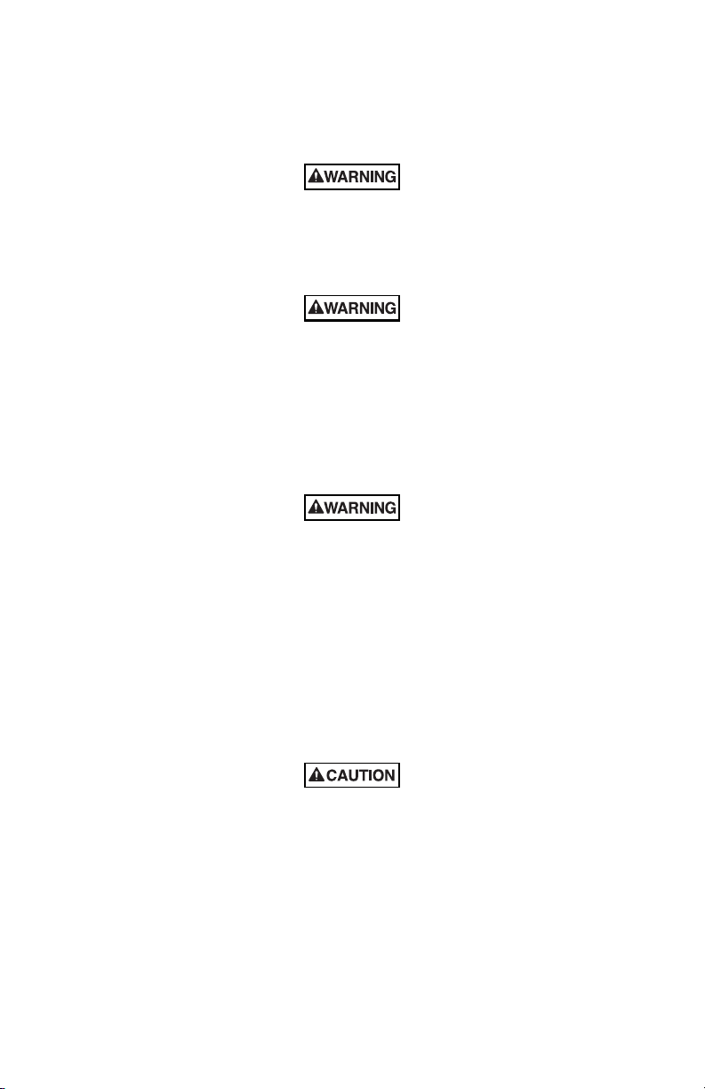
290A5578
MODELS
300GC & 302GC
MODELS
300GCX & 302GCX
A"
C"
B"
1-13/16"
2-9/16"
F
2-3/4"
1/2"-14 NPT
5-5/8"
13/16"
3-3/8"
5-5/8"
13/16"
3-3/8"
5-1/2"
2-1/4"
3-1/4"
5"
B"
A" C"
1/2"-14 NPT
(46)
(65)
(70)
(143)
(21)
(86)
(83)
(57)
(127)
(140)
(21)
(86)
(143)
G
D
E
H
D
1
Français
300GC & 300GCX 302GC & 302GCX
A. 8-1/8» (206) 10» (254)
B. 12-5/8» (320) 15» (381)
C. 8-1/2» (216) 8-1/2» (216)
D. Écrou à embase
E. Bouchon de conduit
F. Entrée défonçable de 22 mm de diamètre (7/8»)
G. 2 trous de montage 5,1mm de diamètre (0,201»)
H. 4 trous de montage 5,1mm de diamètre (0,201»)
Español
300GC y 300GCX 302GC y 302GCX
English
300GC & 300GCX 302GC & 302GCX
A. 8-1/8 pulg (206) 10 pulg (254)
A. 8-1/8" (206) 10" (254)
B. 12-5/8 pulg (320) 15 pulg (381)
B. 12-5/8" (320) 15" (381)
C. 8-1/2 pulg (216) 8-1/2 pulg (216)
C. 8-1/2" (216) 8-1/2" (216)
D. Tuerca de collar
E. Tapón de conducto
D. Collar Nut
F. Abertura rompible de 7/8 pulg (22) de diámetro
G. 2 orificios de montaje de 0,201 pulg (5,1) de diámetro
E. Conduit Plug
F. 7/8" (22) Diameter Conduit Knockout
H. 4 orificios de montaje de 0,201 pulg (5,1) de diámetro
G. 0.201" (5.1) Diameter, 2 Mounting holes
H. 0.201" (5.1) Diameter, 4 Mounting holes
-25-
Page 27

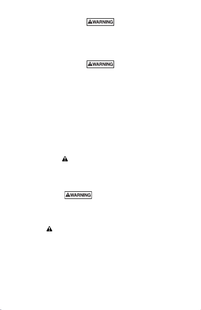
290A5579
L+ L+ N- N-
L+
L+
N-
N-
+
D
C
B
A
2
English
A. Volume Control
B. Tone/Connector Card Socket
C. Power Connector Plug
D. Earth Grounding Terminal
Español
A. Control de volumen
B. Receptáculo de la tarjeta de conexión/tono
C. Tapón del conector de potencia
D. Terminal de conexión a tierra
Français
A. Commande de volume
B. Prise femelle pour carte de connecteur/tonalité
C. Connecteur d’alimentation
D. Borne de mise à la terre
Page 28

2562226A
REV. A Printed 9/06
Printed in U.S.A.
 Loading...