

Federal Industries ITRSS3626 Installation Manual

- 1 -
E3788
8/20/19 Rev K
INSTALLATION & OPERATIONS INSTRUCTIONS
ITR & ITRSS: Self-Contained & Remote Refrigerated Models
ITD & ITDSS: Non-Refrigerated Displays
KEEP THIS MANUAL FOR FUTURE REFERENCE
Engineering and technical data are subject to change without notice.
FEDERAL INDUSTRIES 215 FEDERAL AVE Belleville, WI 53508
Toll Free 1(800) 356-4206 WI Phone (608) 424-3331 Fax: (608) 424-3234

- 2 -
CONTENTS
INTRODUCTION ....................................................................................................................................... 4
Registration and Serial Number ...................................................................................................... 4
WARNING LABELS & SAFETY INSTRUCTIONS .............................................................................. 5
GENERAL ELECTRICAL & GROUNDING ..................................................................................... 6-8
Refrigerated Permanent Connected .............................................................................................. 6,7
Refrigerated Floor Models ......................................................................................................... 7
Refrigerated Counter Models ..................................................................................................... 7
Refrigerated Cord Connected (Option) ............................................................................................ 7
Non-Refrigerated Cord Connected ................................................................................................... 8
REFRIGERATION ............................................................................................................................... 9-11
Self-Contained Models ..................................................................................................................... 9
Self-Contained Refrigeration Operation ...................................................................................... 9
Remote Models ................................................................................................................................ 9
Remote Refrigeration Operation ................................................................................................. 9
Remote Refrigeration Instruction .............................................................................................. 10
Condensate Evaporator pan and Pump ........................................................................................... 11
Condensate Evaporator ............................................................................................................. 11
Condensate Pump ..................................................................................................................... 11
Electronic Expansion Valve (EEV) After 12/1/19………………………………………………..12
EEV Controller Settings………………………………………………………………………12
BASE COMPONENT LAYOUT ....................................................................................................... 13-19
Refrigerated Self Contained Models ........................................................................................ 13-16
Refrigerated Remote Models .................................................................................................... 17-18
Non-Refrigerated Models ............................................................................................................... 19
INSTALLATION INSTRUCTIONS, FLOOR MODELS ..................................................................... 20
Inspection for Shipping Damage .................................................................................................... 20
Locating the Display Case .............................................................................................................. 20
Removing Case from Shipping Skid .............................................................................................. 20
Additional Parts .............................................................................................................................. 20
Cleaning ......................................................................................................................................... 20
INSTALLATION INSTRUCTIONS COUNTER MODELS .......................................................... 21-27
Inspection for Shipping Damage .................................................................................................... 21
Locating the Display Case .............................................................................................................. 21
Removing Case from Shipping Skid .............................................................................................. 21
Additional Parts .............................................................................................................................. 21
Cleaning ......................................................................................................................................... 21
ITD & ITDSS Non-Refrigerated Models Cabinet Mounting ......................................................... 22
Cabinet Preparation ..................................................................................................................... 22
ITR Refrigerated Models Cabinet Mounting ................................................................................. 23
Cabinet Preparation ..................................................................................................................... 23
Cabinet Cut Out ........................................................................................................................... 23
Case Install .................................................................................................................................. 24
Counter Air Duct & Grills ........................................................................................................... 25
JOINING CASES, NO END GLASS ............................................................................................. 26
JOINING FLOOR MODEL BASES, NO END PANELS .............................................................. 27
JOINING CASES, SINGLE END GLASS ..................................................................................... 28
JOINING FLOOR MODEL BASES, SINGLE END PANELS ..................................................... 29
COMPARTMENT PANEL REMOVAL .......................................................................................... 30-32
Refrigerated Base Models Back Panel ........................................................................................... 30
Refrigerated & Non-Refrigerated Base Models Back Panel .......................................................... 30
Refrigerated Counter Models Front and Back Panels .................................................................... 31
Non-Refrigerated Models Top Cover ............................................................................................. 32
END PANEL INSTALLATION & REMOVAL .................................................................................... 33

- 3 -
SHELVING INSTALLATION & REMOVAL ................................................................................ 34-38
Shelf Brackets & Supports ....................................................................................................... 34-36
LED Light Plug Connection ........................................................................................................... 36
Glass Shelves ................................................................................................................................. 37
Horizontal Dual Zone Shelf Divider ............................................................................................. 38
FRONT AND REAR DOORS REMOVAL ...................................................................................... 39-40
ITR, ITD, & ITDSS Rear Doors .................................................................................................... 39
ITRSS Rear Inner and Outer Doors................................................................................................ 40
SECURITY NIGHT COVER (OPTION) ............................................................................................... 41
OPERATING INSTRUCTIONS ....................................................................................................... 42-47
Power Switch ................................................................................................................................................ 42
Light Switch ................................................................................................................................................. 42
Temperature Control ................................................................................................................................ 42-46
Button and Display Overview ................................................................................................................. 43
Powering on Control ............................................................................................................................... 43
Adjusting the Set Point ............................................................................................................................ 44
Entering Manual Defrost Mode ............................................................................................................... 44
Error Codes ........................................................................................................................................ 44-45
Electronic Control Operation ............................................................................................................. 45-46
Control Parameters ................................................................................................................................. 46
Initial Startup .................................................................................................................................. 47
Placing Product in Case .................................................................................................................. 47
MAINTENANCE ................................................................................................................................ 48-49
Cleaning Condenser Coil................................................................................................................ 48
Top LED Strip Replacement .......................................................................................................... 49
Shelf LED Replacement ................................................................................................................. 49
CLEANING INSTRUCTIONS .......................................................................................................... 50-54
Daily Cleaning ................................................................................................................................ 50
Weekly Cleaning ITR, ITD, & ITDSS ..................................................................................... 51-52
Weekly Cleaning ITRSS .......................................................................................................... 53-54
Weekly Exterior Cleaning .............................................................................................................. 54
SERVICE ............................................................................................................................................. 55-56
Service Information ........................................................................................................................ 55
Pre-Service Checklist ..................................................................................................................... 56
SALE & DISPOSAL ................................................................................................................................. 56
Owner Responsibility ..................................................................................................................... 56
WIRING DIAGRAMS ........................................................................................................................ 57-60
REPLACEMENT PARTS .................................................................................................................. 61-62
- 4 -
INTRODUCTION
Thank you for purchasing a Federal Industries display case. This manual contains important instructions for
installing and servicing the Refrigerated Self-Service Merchandisers. A repair parts list and wiring diagram
are also included in the manual. Read all of these documents carefully before installing or servicing your
case.
NOTICE
Read this manual before installing your case. Keep this manual and refer to it before doing any
service on the equipment. Failure to do so could result in personal injury or damage to the case.
NOTICE
Installation and service of the electrical components in the case must be performed by a licensed
electrician.
The portions of this manual covering components contain technical instructions intended only for persons
qualified to perform electrical work.
DANGER
Improper or faulty hookup of electrical components in the case can result in severe injury or death.
All electrical wiring hookups must be done in accordance with all applicable local, regional, or
national standards.
REGISTRATION & SERIAL NUMBER
It’s important to keep a record of the model and serial number of your merchandiser for warranty and part
identification. Please write them here for your quick reference.
Register your product online! Visit our website at www.federalindustries.com and register your product
today.
Case Model__________________________ Serial Number______________________
We’re here to provide you with the best possible experience with your new product, however, we cannot
cover everything about your merchandiser in this manual, so if you have any additional questions or issues,
please see the SERVICE INFORMATION PAGE to find who you should contact.
- 5 -
WARNING LABELS & SAFETY INSTRUCTIONS
CAUTION
POWER BEFORE
RISK OF ELECT
RIC
SHOCK DISCONNECT
91-12340
SERVICING UNIT.
CAUTION
HAZARDOUS MOVI
NG PARTS
D
O N
OT OPERATE UNI
T WITH
DISPLAY PANS
REMOVED.
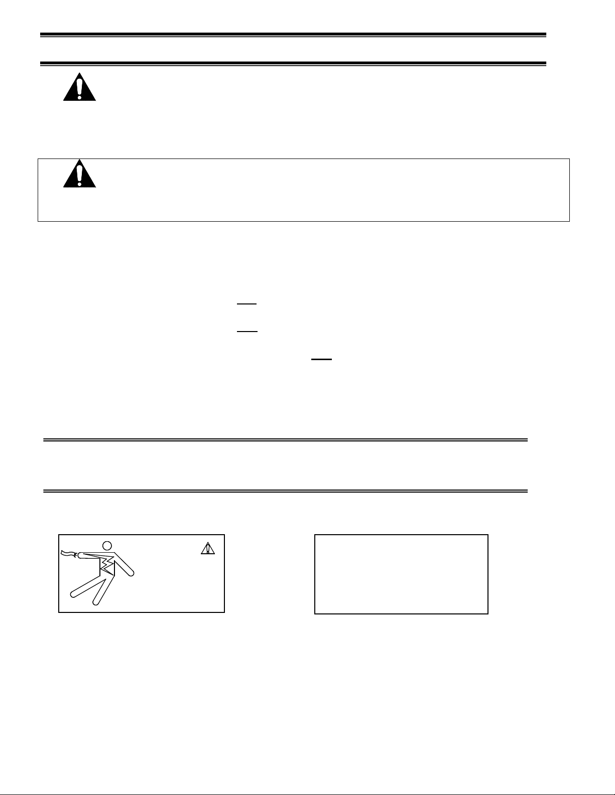
This is the safety-alert symbol. When you see this symbol on your case or in the manual, be alert to the potential for personal injury or damage to your equipment.
Be sure you understand all safety messages and always follow recommended precautions and safe
operating procedures.
NOTICE TO EMPLOYERS
You must make sure that everyone who installs, uses, or services your case is thoroughly
familiar with all safety information and procedures.
Important safety information is presented in this section and throughout the manual. The Following signal words are used in the warning and safety messages:
DANGER: Severe injury or death will occur if you ignore the message.
WARNING: Severe injury or death can occur if you ignore the message.
CAUTION: Minor injury or damage to your case can occur if you ignore the message.
NOTICE: This is important installation, operation, or service information. If you ignore the
message, you may damage your case.
The warning and safety labels shown throughout this manual are placed on your Federal
Industries case at the factory. Follow all warning label instructions. If any warning or safety labels
become lost or damaged, call our customer service department at 1(800) 356-4206 for replacements.
This label is located on the back of the display case. This label is located below the display pan.

- 6 -
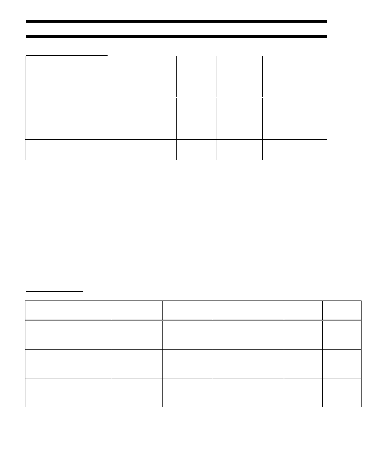
GENERAL ELECTRICAL & GROUNDING
MODEL PERMANENT CONNECTED AMPS CORD CONNECT AMPS/ NEMA PLU G COMPRESSOR L RA
ITR3626 & ITR3634 MIN CI RCUI T AMPACI TY 13 .9 / MAX FUSE S I ZE 20 TOTAL AMPS 8 .7 / 5 - 15 TOTAL AMPS 8 .7 / 5 - 15
ITR4826 & ITR4834 MIN CI RCUI T AMPACI TY 16 .9 / MAX FUSE S I ZE 20 TOTAL AMPS 10 .7 / 5 - 15 TOTAL AMPS 10 .7 / 5 - 15
ITR6026 & ITR6034 MIN CI RCUI T AMPACI TY 17 . 3 / MAX FUSE SI ZE 2 0 TOTAL AMPS 11. 0 / 5 - 15 TOTAL AMPS 11.0 / 5 - 15
ITRSS3626 & ITRSS3634 MIN CI RCUI T AMPACI TY 17 . 11/ MAX FUS E SI ZE 2 0 TOTAL AMPS 13.6 / 5-20 TOTAL AMPS 13.6 / 5-20
ITRSS4826 & ITRSS4834 MIN CI RCUI T AMPACI TY 2 0 / MAX FUSE SI ZE 25 TOTAL AMPS 13.8 / 5-20 TOTAL AMPS 13.8 / 5-20
ITRSS6026 & ITRSS6034 MIN CI RCUI T AMPACI TY 13 .6 5/ MAX FUSE S I ZE 20 TOTAL AMPS 10 .1 / 6 - 15 TOTAL AMPS 10 .1 / 6 - 15
MODEL VOL TAGE PERMANENT CONNECTED AMPS
ITR3626 & ITR3634
ITRSS3626 & ITRSS3634
120V/60H/1PH MIN CI RCUI T AMPACI TY 15 / MAX FUSE S I ZE 15
ITR4826 & ITR4834
ITRSS4826 & ITRSS4834
120V/60H/1PH MIN CI RCUI T AMPACI TY 15 / MAX FUSE S I ZE 15
ITR6026 & ITR6034
ITRSS6026 & ITRSS6034
120V/60H/1PH MIN CI RCUI T AMPACI TY 15 / MAX FUSE S I ZE 15
MODEL PERMANENT CONNECTED AMPS CORD CONNECT AMPS/ NEMA PLU G
ITD3626 & ITD3634
ITDSS3626 &ITDSS3634
MIN CI RCUI T AMPACI TY 15 / MAX FUSE S I ZE 15 TOTAL AMPS 2 .0 / 5 - 15
ITD4826 & ITD4834 ITDSS
4826 & ITDSS4834
MIN CI RCUI T AMPACI TY 15 / MAX FUSE S I ZE 15 TOTAL AMPS 2 .0 / 5 - 15
ITD6026 & ITD6034
ITDSS6026 & ITDSS 6034
MIN CI RCUI T AMPACI TY 15 / MAX FUSE S I ZE 15 TOTAL AMPS 2 .0 / 5 - 15
SEL F CONTAI NED
VOL TAGE
120V/60H/1PH
120V/60H/1PH
120V/60H/1PH
120V/60H/1PH
120V/60H/1PH
230/60H/1PH
DRY NON REFRIGERATED
VOL TAGE
120V/60H/1PH
120V/60H/1PH
120V/60H/1PH
REMOT E
DANGER: Improper or faulty hookup of electrical components in the
display case can result in severe injury or death.
(E3788 EXCEL)
Refrigerated Permanent Connected
-Only a licensed electrician must perform all case electrical connections.
-All electrical wiring hookups must be done in accordance with all applicable local, regional, or national
electrical standards.
-A separate circuit for each display case is required to prevent other appliances on the same circuit from
overloading the circuit and causing malfunction.
-The electrical service must be grounded upon installation.
-See the electrical data plate located at the rear of the case for proper circuit size and wire ampacity.
-The electrical connection box is accessible from the rear of the case with rear grill removed. See grill
removal section of this manual for grill removal procedure.

- 7 -
Refrigerated Floor Models:
Refrigerated Counter Models:
Refrigerated Cord Connected (OPTION)
-A factory installed optional power cord is properly sized to the amperage requirements of the case. See the
electrical data plate located on the rear exterior of the case for the proper circuit size for each case.
- The cord is factory installed protruding from the rear corner of the case as noted in above drawings.
-A separate circuit for each display case is required to prevent other appliances on the same circuit from
overloading the circuit and causing malfunction.
CAUTION Risk of Electric Shock. If the cord or plug becomes damaged,
replace only with a cord and plug of the same type".

- 8 -
Non-Refrigerated Cord Connected (STANDARD)
-A factory installed power cord is properly sized to the amperage requirements of the case. See the
electrical data plate located on the rear exterior of the case for the proper circuit size for each case.
- The cord is factory installed protruding from the rear corner of the case as noted in below drawings.
-A separate circuit for each display case is required to prevent other appliances on the same circuit from
overloading the circuit and causing malfunction.
CAUTION Risk of Electric Shock. If the cord or plug becomes damaged,
replace only with a cord and plug of the same type".
- Only a licensed electrician can move the electrical cord connections to opposite end of case as shown in
drawings below.
NON-Refrigerated Floor Models:
NON-Refrigerated Counter Models:
- 9 -
REFRIGERATION
MODEL
R134A
12/1/19
R531A
12/1/19
REFRIGERATION
ITR3626 & ITR3634 & ITRSS3626 &
ITRSS3634
18 OZ
17 OZ
1/2HP
ITR4826 & ITR4834 & ITRSS4826 &
ITRSS4834
20 OZ
19 OZ
1/2HP
ITR6026 & ITR6034 & ITRSS6026 &
ITRSS6034
24 OZ
23 OZ
1/2HP
MODEL
REFRIGERANT
PRE 12/1/19
REFRIGERANT
POST 12/1/19
REFRIGERATION
PRESSURE
CUT IN
PRESSURE
CUT 0UT
ITR3626R & ITR3634R &
ITRSS3634R
R134A
R531A
BTUH@90F/20F
25#
5 #
ITR4826R & ITR4834R &
ITRSS4834R
R134A
R531A
BTUH@90F/20F
25#
5 #
ITR6026R & ITR6034R &
ITRSS6034R
R134A
R531A
BTUH@90F/20F
25#
5 #
Self-Contained Models
CHARGE
PRE
CHARGE
POST
The self-contained models manufactured before 12/1/19 are shipped from the factory with a completely
operational 134A refrigeration system and require no modifications or adjustments upon installation.
Models produced after 12/1/19 are shipped with 531A. Case must be installed per the installation section of
this manual to provide proper condensing air cooling.
Self-Contained Refrigeration Operation
The unit temperature is controlled by an electronic control that senses air temperature and turns
refrigeration on and off as required to maintain proper temperature.
The electronic control will also sense a frosted coil that requires a defrost cycle and shuts off refrigeration
until defrost is complete. There are also a defined number of scheduled defrosts that also shut the
refrigeration off to insure a full defrost.
Remote Models Use pressure gauges to set pressure control
ITRSS3626R &
ITRSS4826R &
ITRSS6026R &
Use pressure gauges to set pressure control
3400
3800
4200

- 10 -
Remote Refrigeration Operation
The remote models manufactured before 12/1/19 are designed to use 134A refrigerant and after 12/1/19 are
designed to use R531a refrigerant and shipped from the factory with the evaporator coil, expansion valve,
drier filter, sight glass and refrigerant solenoid valve. The required high-low-pressure control and remote
condenser can be provided as a factory option and will be required to be charged with 134a or R531A
refrigerant after installation.
The unit temperature is controlled by an electronic control that senses air temperature and opens and closes
the refrigerant solenoid valve as required to maintain proper temperature.
Once proper temperature is reached the solenoid valve closes and shuts off the refrigeration flow to the unit
and initiates a pump down cycle. This will allow the remote low pressure switch to open and shut off
remote compressor. The solenoid will remain closed until the electronic control probe reaches its “cut in”
set point. The electronic control will also sense a frosted coil that requires a defrost cycle and closes
solenoid until defrost is complete. There are also a defined number of scheduled defrosts that also insures a
full defrost occurs.
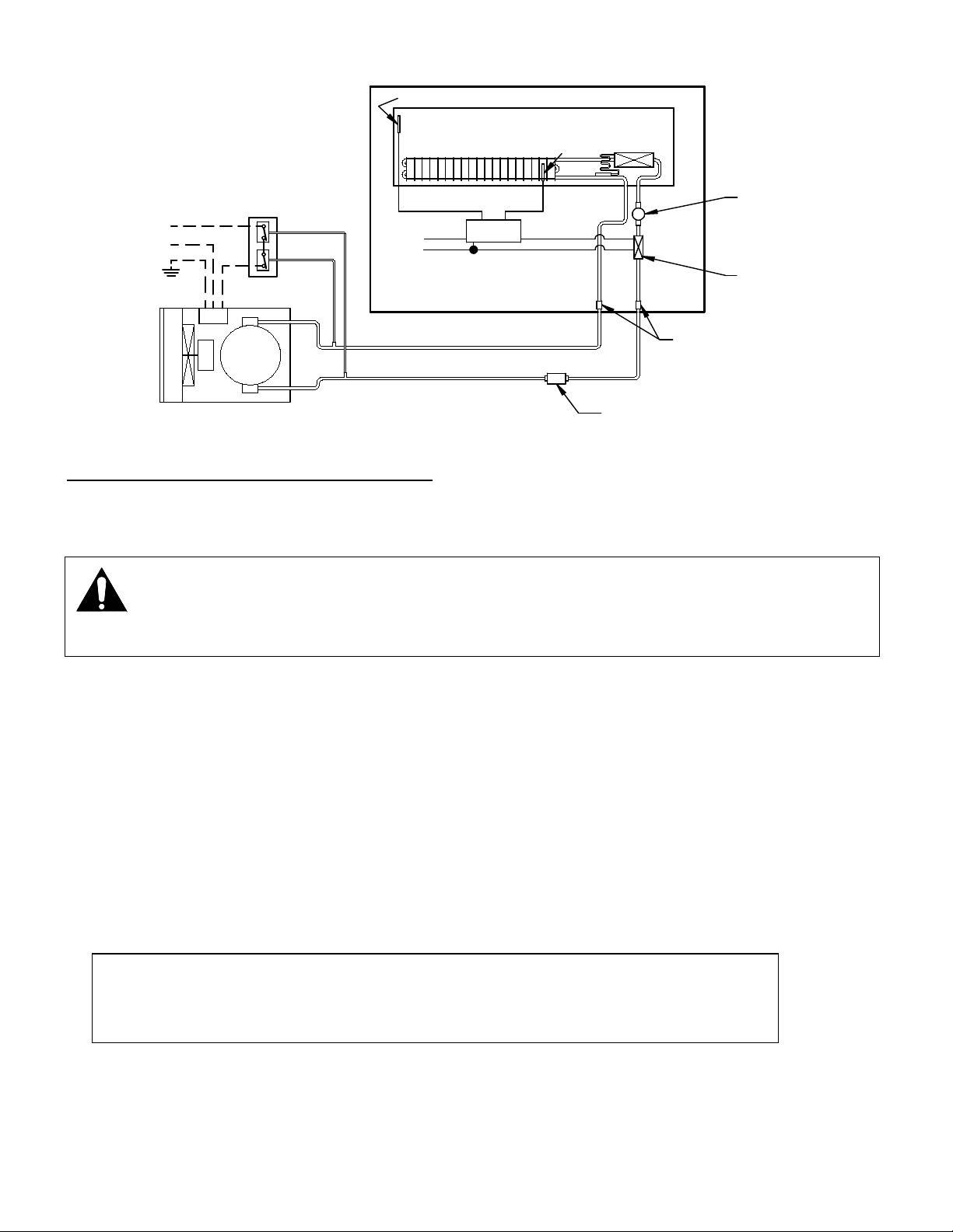
Remote Refrigeration Installation
The condensing unit and pressure control are optionally supplied from the factory for remote location
installation. A remote high low-pressure switch must be mounted and wired by the installer. The high lowpressure switch must be wired in series with the compressor power supply as shown in diagram below.
1. Mount condensing unit as close to the remote display case as practical. All refrigeration and/or
electrical materials between the condensing unit and display case are to be supplied by installing
contractor.
2. Route properly sized and designed refrigeration lines from the condensing unit to the cabinet. Follow
line sizing charts and piping instructions in the condenser unit’s manufacturers instruction manual.
Horizontal suction lines should be pitched downward towards the condensing unit at least ½” per 10’
run to aid the oil drainage. A “P” trap must be installed in the suction line at the foot of every riser to
insure oil return. Dry nitrogen must be used to flow through tubing while brazing refrigeration lines.
3. Suction line must be insulated the entire length with Armaflex (or equivalent). Do not run liquid line
inside insulation with suction line.
4. The remote high/low-pressure control must be mounted, wired and set by the installer.
5. Leak check condensing unit, cabinet, and all connecting tubing. Cabinet and condensing unit tubing
should be checked to insure no leaks occurred during shipping or from rough handling.
Make certain all refrigeration valves are opened and evacuate system below 500 microns. System must
hold below 500 microns for 1 minute with pump isolated. Charge the system with refrigerant type
specified on the data plates.
- 11 -
REMOT E
HI GH LOW
PRESSURE
CONT ROL
L I QUI D L INE
SUCT I ON L I NE (I NSUL ATED)
REMOT E
CONDENSI NG
UNI T
EVAPORATOR
COI L S
DI SPL AY CASE
EXPANSION
VALVE
HI GH
L OW
L I QUI D L I NE
SOL ENOI D VAL VE
SI GHT GL AS S
DRI ER/ FILTER
FI EL D CONNECTI ON
HOT
FUSED
POWER
SUPPL Y
DEFROST
TERMI NATE
PROBE
ELECT RONIC
CONT ROL
AI R TEMP. CONTROL PROBE
FUSED
CASE
POWER
NOTICE: This unit could be shipped with an optional condensate pump. The pump
cleaned and inspected every 3-4 months.
Condensate Evaporator Pan and Pump
Condensate Evaporator (Standard Self-Contained Models)
NOTICE: During normal defrost cycles, steam from the condensate
evaporator may be visible around the case.
The standard Self-Contained case is furnished with an electric condensate evaporator. Plumbing
connections are not required.
The condensate evaporator can be removed from the case and the condensate drain can be plumbed to a
drain to conserve energy if desired. Disconnect the condensate evaporator wires at the condensate
evaporator to remove. This must be done by a qualified electrician.
Make sure that the drain line has not been dislodged during shipment and that the drain trap terminates
properly over the water reservoir.
Condensate Pump (Standard Remote, optional Self Contained)
When unit is shipped with a condensate pump a condensate discharge hose is supplied from factory. This
has a float that turns the pump on automatically when needed.
The pump is mounted in the base compartment. The pump should be
hose must be run to a nearby drain. When the condensate pan is full the pump will turn on and pump water

- 12 -
out condensate drain hose. Note Drain hose can be run in vertical direction but must not exceed height of
15 feet
Note: There is a piece of cardboard that has to be removed from the side of the pump to free up the
float. If this is not done, the pump will not turn on and the pan will overflow.
Electronic Expansion Valve (EEV) After 1/20
A traditional TXV uses springs and a temperature bulb to open and close a valve port that controls the flow
of refrigerant entering the evaporator coil. An electronic expansion valve (EEV) controls the refrigerant
flow much more precisely, increasing the performance and efficiency of the refrigeration system. The EEV
controls the flow of Refrigerant by opening and closing the valve port based on the response to signals sent
to the EEV by an electronic controller. The electronic Control bases these signals by processing
information provided from a temperature sensor and pressure transducer located on the discharge side of
the evaporator coil.
These sensors monitor the evaporator superheat and protects the compressor from any liquid flood back
under low superheat conditions.
EEV Controller Settings
The electronic expansion valve controller also allows the use of different types of refrigerants without the
need to change the expansion valve.
The controller is set from the factory to run on 449A refrigerant and will not need any changes to the
control unless another refrigerant is used.
Note: Check your State and Local regulations for approved refrigerants for your install location.
Federal Industries is not liable for any alternate refrigerants used.
The control is located in the rear center of the base.
Note: Never change any of the other setting other than the refrigerant type. It may also be necessary
to change the superheat setting only when using a different refrigerant.
- 13 -
Changing Refrigerant
• Access the set point mode by pressing and holding the button until Ctl displays on the screen.
• Use the up or down arrows to advance through the available set points until rFG displays on
the screen and press the botton.
• Use the up or down arrows until the desired refrigeration displays on the screen and press and
hold the button until rFG once again displays on the screen.
• Press the to return to escape the settings menue.
Changing Superheat
• Access the set point mode by pressing and holding the button until Ctl displays on the screen.
• Use the up or down arrows to advance through the available set points until SSP displays on
the screen and press the botton.
• Use the up or down arrows to set the desired superheat displays on the screen and press and
hold the button until SSP once again displays on the screen.
• Press the to return to escape the settings menu.
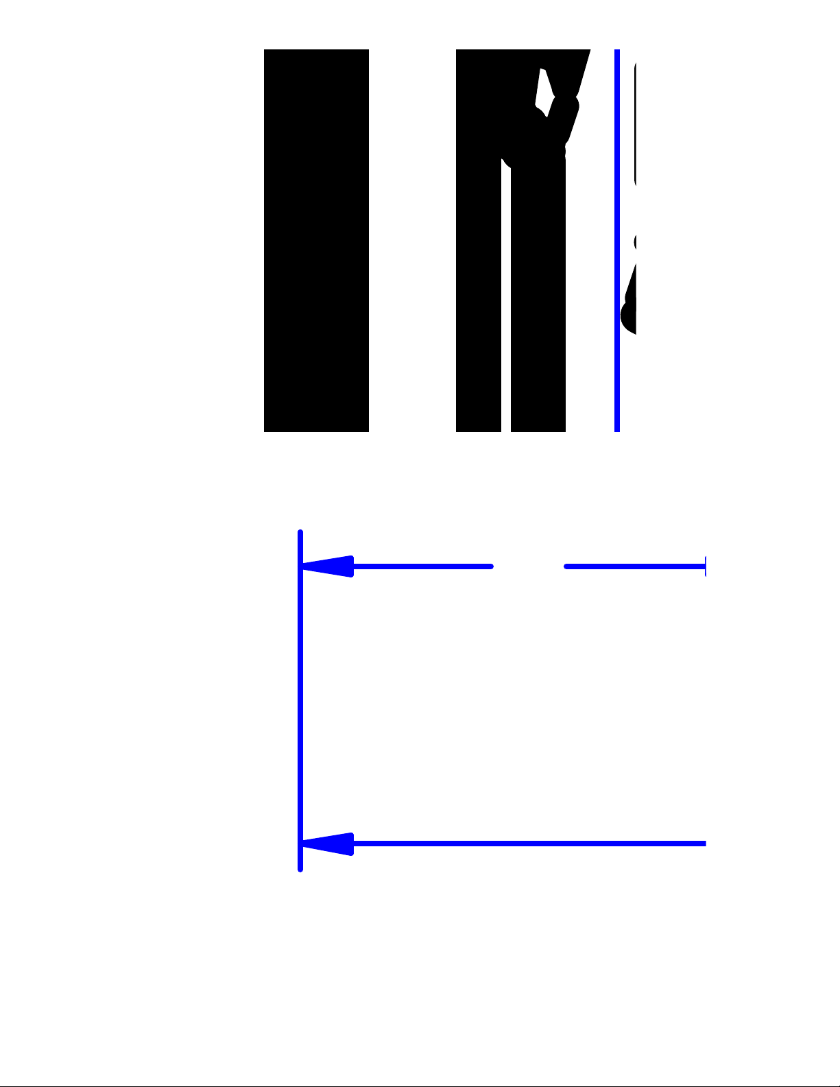
BASE COMPONENT LAYOUTS
Refrigerated Self Contained Models
Counter ITR & ITRSS 36 Self Contained
Counter ITR & ITRSS 48 Self Contained
- 14 -
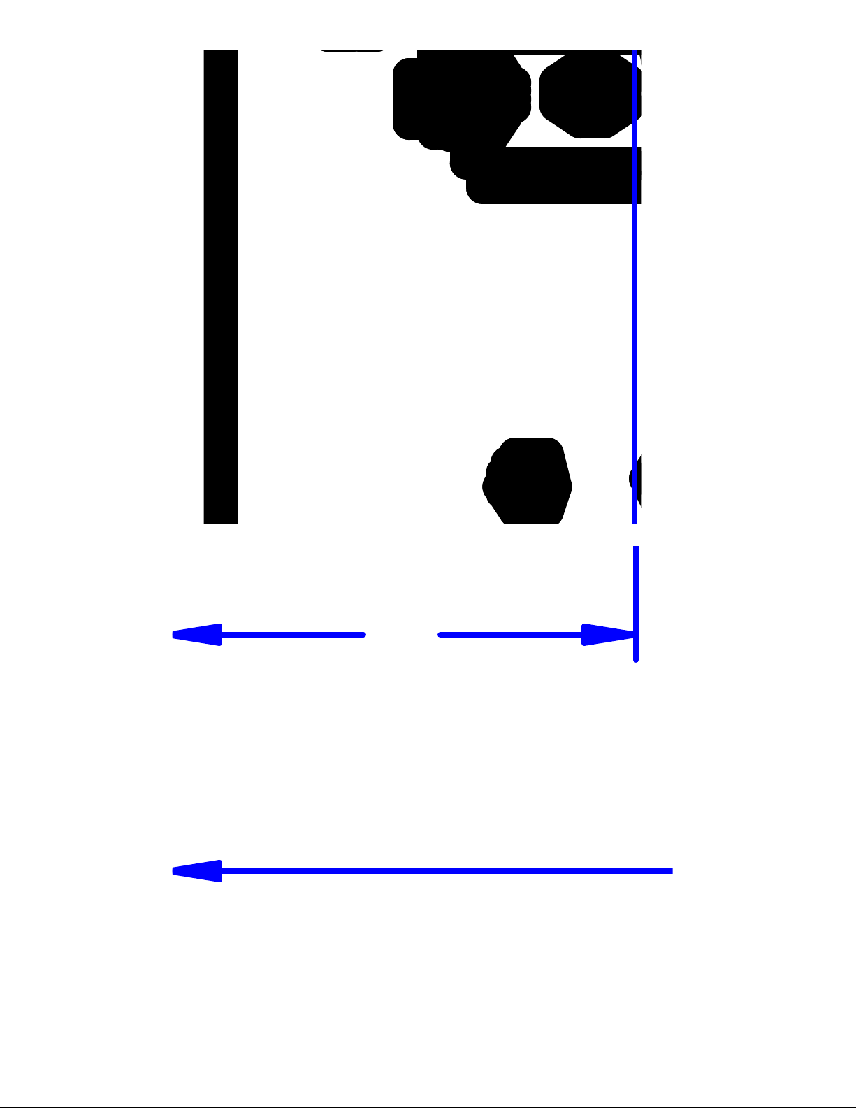
Counter ITR60 Self Contained
Counter ITRSS60 Self Contained

- 15 -
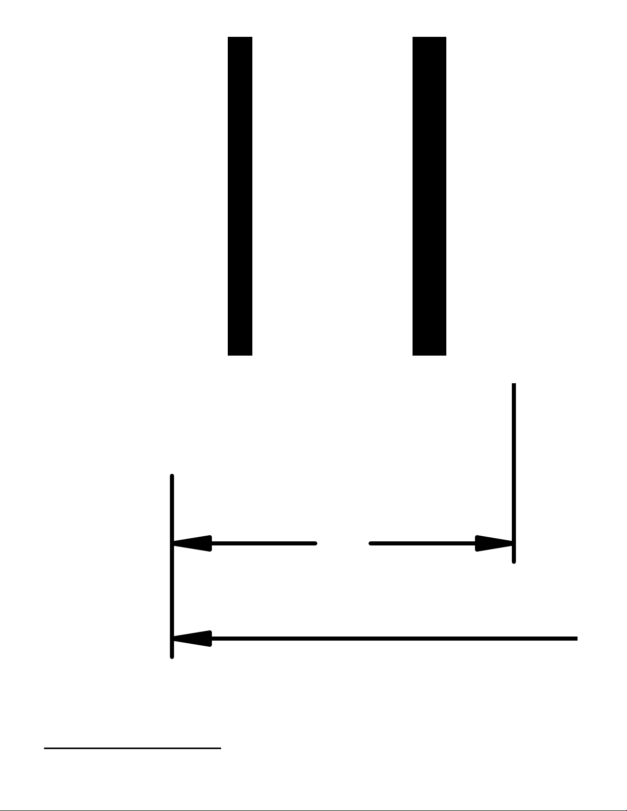
Floor ITR & ITRSS 36 Self Contained
- 16 -
Floor ITR & ITRSS 48 Self Contained
Floor ITR60 Self Contained
- 17 -
Floor ITRSS60 Self Contained
Refrigerated Remote Models
- 18 -
All ITR Counter Remote
All ITR Floor Remote
All ITRSS Counter Remote
- 19 -
All ITRSS Floor Remote
Floor ITD & ITDSS NON-Refrigerated

- 20 -
There are no components in base on NON-Refrigerated models so no base layout is provided
Light Power Supply is located on top of case under the top cover. See Removal Section of this Manual.
 Loading...